PHYSICAL INSTALLATION
WARNING: DISCONNECT POWER BEFORE INSTALLING, REMOVING, OR SERVICING UNIT
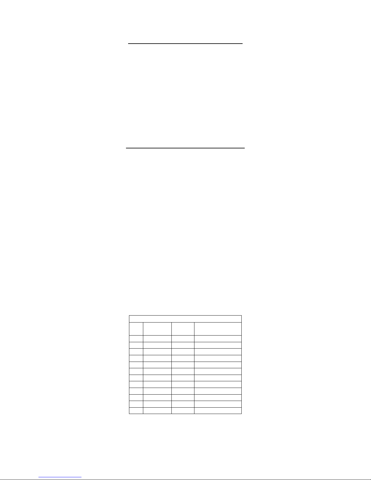
Concept 3 Otterbine aerators require a minimum 30"/75cm (40"/100cm w/ lights) of water depth.
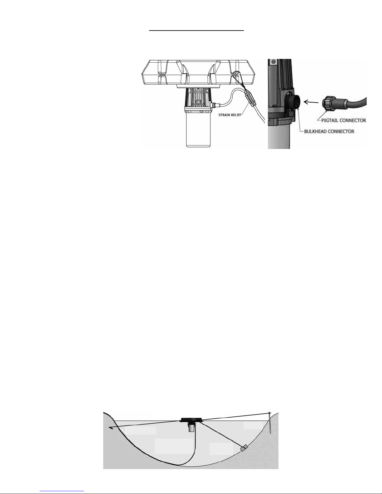
A. Attach your Otterbine power cable
to the aerator.
1. Align the keyway on the cable pigtail
connector to the key on the aerator
bulkhead connector and plug together.
Thread the nut onto the bulkhead, hand
tighten only, do not use tools on the
pigtail connector nut.
Over tightening may cause the
connector to fracture and possibly
cause an electrical short circuit.
2. 5HP, 230V, 1 Phase units have a 3
pin bulkhead connector and a 3 pin
pigtail connector on the power cable. All
other ratings use 4 pin connectors.
3. A small amount of silicon compound has been factory applied to the female end of the aerator connector. The
compound is necessary to make a waterproof seal between the two connectors. DO NOT REMOVE COMPOUND! When
servicing the aerator re-apply compound. (Otterbine P/N: 48-0001).
4. Install the cable strain relief device. Pass the wire hoop from the strain relief through one of the holes in the float or
around the float bracket. Reattach wire hoop to strain relief (see above).
5. For additional protection fasten the power cable, after the strain relief, to a float hole using the cable ties provided.
B. Pre-Startup Checks (To be performed by a qualified technician)
1. Factory connections may loosen during shipping. Verify tightness of all screw terminal connections before energizing.
2. Apply power to the PCC. Verify the incoming voltage is correct at the input terminals and matches the nameplate rating
of the aerator. For 115V & 230V Single Phase & 230V Three Phase Units: The voltage between L1 on the input
terminal block to the neutral terminal must measure a nominal 120V.
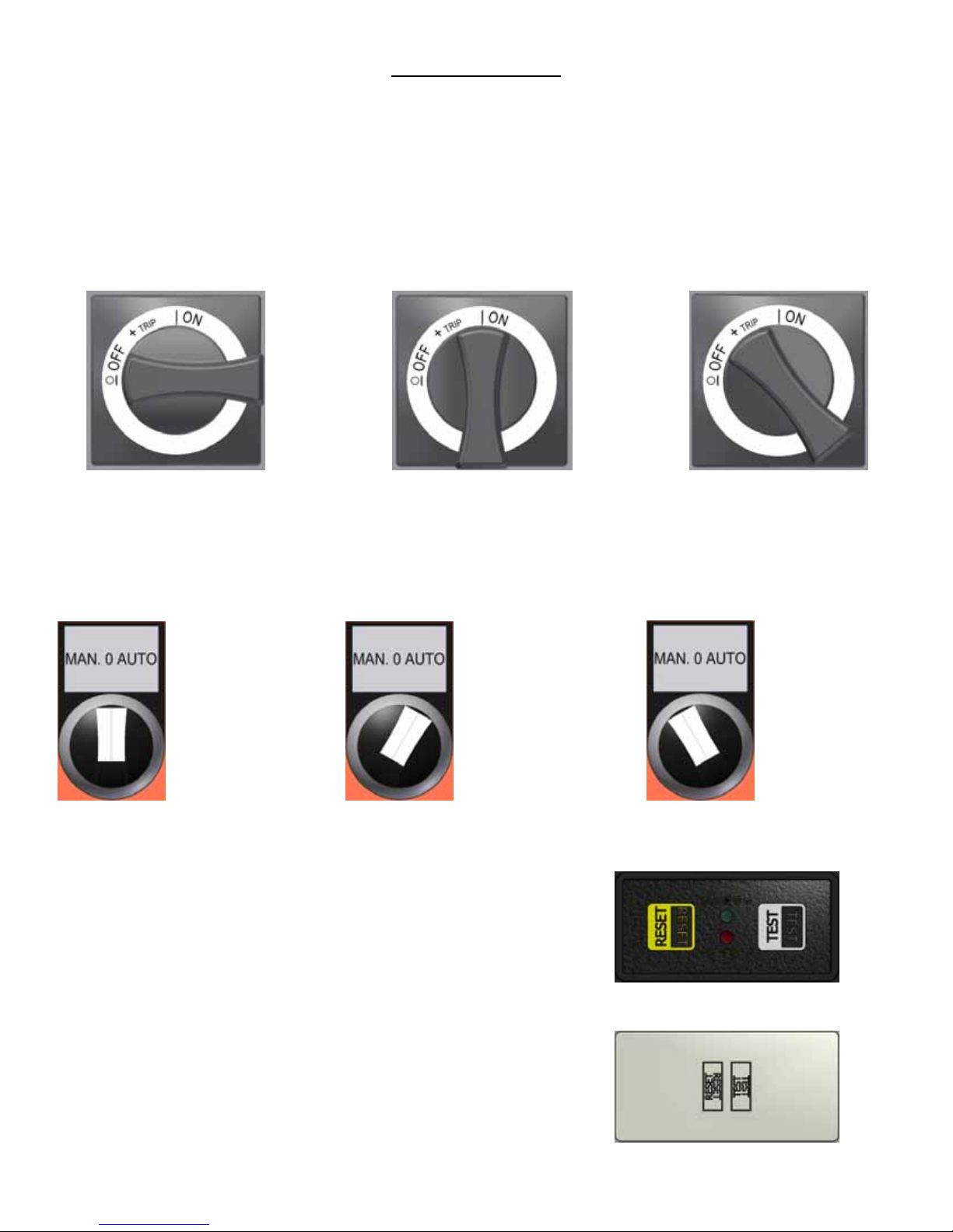
3. Allowing the main door to be open and with the swing panel door closed follow GFCI instructions on page 11 to reset
aerator GFCI. Turn on disconnect and proceed.
4. With the aerator unit on the shore check for correct motor rotation. Briefly “bump” the M-O-A switch (Shown on Page 10) to
“MAN” while observing the motor shaft rotation (turn on only long enough to establish operation and proper direction of
rotation). Aerator Shaft rotation MUST BE CCW looking at the top/impeller end of the unit.
!TURN OFF DISCONNECT BEFORE PROCEEDING!
C. Fasten Mooring Lines and Launch
1. Mooring using stakes: Shore mounted stakes provides the easiest access to the aerator. Use stainless steel and/or
brass hardware. Otterbine recommends using 1/4"(0.63cm) or 1/2"(1.25cm) polypropylene rope or stainless steel cable
for mooring lines. At the mooring points use a wooden or metal stake or duck bill type earth anchors. Earth anchors allow
the mooring lines to be hidden beneath the water surface. Drive the mooring stakes securely into the ground at the edge
of the pond or place earth anchors close to the shore in the water. Fasten the mooring lines to opposite outer holes in the
aerator float. Launch the aerator into the water, pull into the chosen location and fasten the lines to the stakes allowing
slack for the aerator to twist up to 1/4 turn. The slack in the lines allows for movement during start up, fluctuations in the
water level and wave action. Proceed to System Startup.
2. Mooring using Anchors: Use stainless steel and/or brass hardware. Otterbine recommends using 1/4"(0.63cm) or
1/2"(1.25cm) polypropylene rope or stainless steel cable for anchoring lines, use two 60 - 80 lb. (27 - 36 kilo) weights for
anchors and a boat may be needed. Fasten the mooring lines to opposite outer holes in the float. Launch the aerator
floating upside down (motor housing facing up). With the lines attached drop the anchors into the water at the
predetermined locations. Adjust the lines to allow slack for the aerator up to 1/4 turn twist. The slack in the lines allows for
movement during start up, fluctuations in the water level and wave action.
ELECTRICAL CABLE
MUST NOT BE TIGHT
LEAVE
LA
K
STAKE
EARTH ANCHOR
WEIGHTED
NCHOR
USE TWO (2) MOORING LINES