Ourten OT-PLC302C-RS4 User manual

Page 1 of 6
Model OT-PLC302C-RS4
Power Line Ethernet Extender
OT-PLC302C-RS4 Power Line Ethernet Extender is a high-speed Ethernet signal
transmission device. It can transmit power + Ethernet + RS485 data signals via 2-wire
power line up to 600m, maximum physical rate up to 500Mbps.
This device contains the Transmitter unit and the Receiver unit. There is the built-in noise reduction isolation transformer
and isolation frequency crosstalk function. It transmits multiple signals over one 2-wire cable, used for various middle and
short distance Ethernet signal transmission.
IP Video Surveillance Network Smart Home
Elevator IP Surveillance Intelligent Network Industry

Page 2 of 6
◆Max transmission distance can reach 600m (RVS 2×1mm2)
◆Max physical bandwidth can reach 500Mbps
◆Support power over one cable technology (110 / 220VAC)
◆Support RS485 data transmission
◆Built-in ESD protection circuit, effectively prevent electrostatic damage
◆Support one power cable to simultaneously transmit multiple signals, built-in isolation filter circuit
Power Line: RVV/RVS/RVVP/RVB 2×0.5mm²above Twisted Pair Cable: Cat5 cable or above
Note: Dimension error value ±0.5 mm

Page 3 of 6
Category
Description
Power
Available Voltage Range
100~240VAC
Power Consumption
≤5W / PC
Power Output Transmitter Unit
100~240VAC
220V Output Current
<10A
12V Output Current
<1A
Transmission / Rate
Standard Compliance
IEEE1901, IEEE802.3
RS485 Port Rate
Dial the switch to adjust, support 38400,
56000, 57600,115200
Up Down Agreement
CSMA/CA
Network Rate
Physical Speed
500Mbps
Transmission Speed
88Mbps
Physical Characteristic
Dimensions (L ×W ×H)
89.5mm×152mm×30mm
Material
Aluminum
Net Weight
450g / PC
Operating Environment
Working Temperature
-20℃~60℃
Working Humidity
<95% (Non-condensation)

Page 4 of 6
Transmitter (Slave)
Step
Installation Instruction
Step
Installation Instruction
1
Network equipment is connected to RJ45 port of
transmitter unit (1)
9
Reserved RS232 terminal (9)
2
220V power output/input L and N terminal (2)
10
12VDC power output(10)
3
Grounding terminal of power cable (3)
11
Dial switch of rate setup (11)
4
Connect terminal transmission 220V power line L
and N terminal (4)
①
ERR link disconnect, the indicator is always on
5
Grounding terminal of power line (5)
②
PLC connection is ok, it is always on or flash
6
Grounding terminal of case (6)
③
PWR power indicator, it is always on
7
Signal indicator (7)
④
After connecting network device, when data
exchanges, it starts to flash
8
Connect front-end device to RS485 terminal (8)
⑤
No function, idle indicator
Receiver (Master)
Step
Installation Instruction
Step
Installation Instruction
12
Network equipment is connected to RJ45 port of
receiver unit (12)
20
Reserved RS232 terminal (20)
13
220V power input L and N terminal (13)
21
12VDC power output(21)
14
Grounding terminal of power line (14)
22
Dial switch of rate setup (22)
15
Connect front-end transmission 220V power line
L and N terminal (15)
①
ERR link disconnect, the indicator is always on
16
Grounding terminal of power line (16)
②
PLC connection is ok, it is always on or flash
17
Grounding terminal of casing (17)
③
PWR power indicator, it is always on
18
Signal indicator (18)
④
After connecting network device, when data
exchanges, it starts to flash
19
Connect local device to RS485 terminal (19)
⑤
No function, idle indicator

Page 5 of 6
Tips:
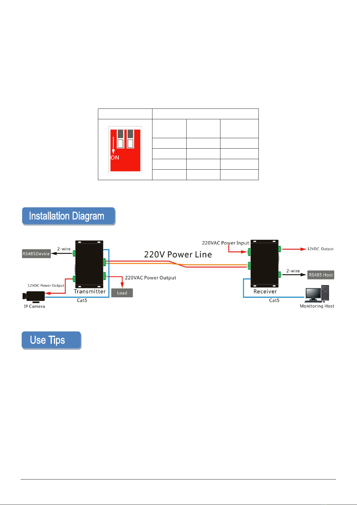
1. When receiver connect 100~240VAC power, transmitter don’t need external power supply, transmitter
provide 12VDC power output.
2. The device supports RS485 data transmission.
3. When the load current is within 10A, the overload will automatically fuse the power circuit to realize circuit
break protection.
Adjust Baud Rate Dial Switch as below:
Diagram
Setup
SW1
SW2
Baud
Rat
ON
ON
115200
ON
OFF
57600
OFF
ON
56000
OFF
OFF
38400
When you use OT-PLC302C-RS4, please follow the below tips as a reference, in order to reduce the fault in the
process of using and the inspection work.
1. Each transmission unit contains one transmitter unit and one receiver unit, when installation, please install receiver
unit at the side of the power supply cabinet, and install transmitter unit at the side of loading equipment.
2. Please make sure power line is disconnected before installation. The metal conductor of the access port should not
be exposed, to avoid short circuit to burn the equipment.
3. Signal transmission cable must be the copper cable. Other material cables will cause the decrease of signal
transmission quality and distance.
4. Long distance cable connection must be formal connection methods, such as welding or using connectors.

Page 6 of 6
5. When the power line system has the protective grounding, please use the special grounding cable to connect the
grounding terminal of the power line system with the grounding terminal of the device.
6. The load current of the front-end equipment should be controlled within 10A, 12VDC output current is 1A. It cannot
work under the saturated current for a long time.
7. There is no waterproof design for this product, please make sure it use in dry environment.
8. If device fails, do not disassemble or repair it by yourself. Please contact us timely.
Attentions: Specifications are subject to change without notice. Thank you for choosing us. For more details,
please visit our website: www.ourten.com
Shaoxing Ourten Electronics Co., Ltd.
3rd Floor # 7, No. 1732 Yanhua industrial park, West Renmin Road, Shangyu, Zhejiang, China
Tel: +86-21-5888 9980 (+86-575-8213 7256)
Fax: +86-575-8212 7256
www.ourten.com
Other Ourten Extender manuals