Outback FX series User manual

FX Inverter/Charger
FX and VFX Mobile Series
Installation Manual

About OutBack Power Technologies
OutBack Power Technologies is a leader in advanced energy conversion technology. OutBack products include true sine wave
inverter/chargers, maximum power point tracking charge controllers, and system communication components, as well as circuit
breakers, batteries, accessories, and assembled systems.
Applicability
These instructions apply to OutBack inverter/charger models FX2012MT, FX2024M, FX2524MT, FX2532MT, FX2536MT, FX3048MT,
VFX2812M, VFX3524M, VFX3232M, VFX3236M, and VFX3648M only.
Contact Information
Address: Corporate Headquarters
17825 – 59th Avenue N.E.
Suite B
Arlington, WA 98223 USA
European Office
Hansastrasse 8
D-91126
Schwabach, Germany
Telephone:
+1.360.435.6030
+1.360.618.4363 (Technical Support)
+1.360.435.6019 (Fax)
+49.9122.79889.0
+49.9122.79889.21 (Fax)
Website: http://www.outbackpower.com
Disclaimer
UNLESS SPECIFICALLY AGREED TO IN WRITING, OUTBACK POWER TECHNOLOGIES:
(a) MAKES NO WARRANTY AS TO THE ACCURACY, SUFFICIENCY OR SUITABILITY OF ANY TECHNICAL OR OTHER INFORMATION
PROVIDED IN ITS MANUALS OR OTHER DOCUMENTATION.
(b) ASSUMES NO RESPONSIBILITY OR LIABILITY FOR LOSS OR DAMAGE, WHETHER DIRECT, INDIRECT, CONSEQUENTIAL OR
INCIDENTAL, WHICH MIGHT ARISE OUT OF THE USE OF SUCH INFORMATION. THE USE OF ANY SUCH INFORMATION WILL BE
ENTIRELY AT THE USER’S RISK.
OutBack Power Technologies cannot be responsible for system failure, damages, or injury resulting from improper installation of
their products.
Information included in this manual is subject to change without notice.
Notice of Copyright
FX and VFX Mobile Series Inverter/Charger Installation Manual © 2016 by OutBack Power Technologies. All Rights Reserved.
Trademarks
OutBack Power, the OutBack Power logo, FLEXware, and OPTICS RE are trademarks owned and used by OutBack Power
Technologies, Inc. The ALPHA logo and the phrase “member of the Alpha Group” are trademarks owned and used by Alpha
Technologies Inc. These trademarks may be registered in the United States and other countries.
Date and Revision
August 2016, Revision A
Part Number
900-0197-01-00 Rev A

900-0197-01-00 Rev A 3
Table of Contents
Introduction..................................................................................................... 5
Audience .........................................................................................................................................................................................5
Symbols Used ................................................................................................................................................................................5
Welcome to OutBack Power Technologies.........................................................................................................................6
General Safety ...............................................................................................................................................................................6
Models..............................................................................................................................................................................................7
Sealed Mobile Models .............................................................................................................................................................................7
Vented Mobile Models............................................................................................................................................................................7
Inverter Model Names.............................................................................................................................................................................7
Components and Accessories ..............................................................................................................................................................8
Planning .......................................................................................................... 9
Applications ...................................................................................................................................................................................9
Renewable Energy................................................................................................................................................................................. 10
Battery Bank............................................................................................................................................................................................. 10
Generator.................................................................................................................................................................................................. 12
Installation..................................................................................................... 13
Location and Environmental Requirements.................................................................................................................... 13
Tools Required............................................................................................................................................................................ 13
Mounting...................................................................................................................................................................................... 14
Dimensions.................................................................................................................................................................................. 14
Terminals and Ports.................................................................................................................................................................. 15
Wiring ............................................................................................................................................................................................ 16
Grounding ................................................................................................................................................................................................16
DC Wiring ..................................................................................................................................................................................... 18
AC Wiring...................................................................................................................................................................................... 21
AC Sources................................................................................................................................................................................................22
ON and OFF Wiring................................................................................................................................................................... 23
Accessory Wiring....................................................................................................................................................................................23
AUX Wiring .................................................................................................................................................................................. 24
Generator Control.................................................................................................................................................................................. 25
AC Configurations..................................................................................................................................................................... 27
Single-Inverter.........................................................................................................................................................................................27
Multiple-Inverter AC Installations (Stacking)................................................................................................................................ 28
Stacking Configurations ......................................................................................................................................................................30
Commissioning .............................................................................................. 41
Functional Test........................................................................................................................................................................... 41
Pre-startup Procedures ........................................................................................................................................................................41
Startup.......................................................................................................................................................................................................41
Powering Down...................................................................................................................................................................................... 43
Adding New Devices............................................................................................................................................................................. 43
Operation ..................................................................................................................................................................................... 43
Definitions.................................................................................................................................................................................... 43
Index ............................................................................................................. 45

Table of Contents
4 900-0197-01-00 Rev A
List of Tables
Table1ComponentsandAccessories..................................................................................................8
Table2BatteryBankElements..........................................................................................................11
Table3GroundConductorSizeandTorqueRequirements...............................................................16
Table4DCConductorSizeandTorqueRequirements......................................................................18
Table5StackingModesforMobileFXInverters................................................................................29
Table6TermsandDefinitions............................................................................................................43
List of Figures
Figure1FXMobileSeriesInverter/ChargerwithTurboFan.................................................................6
Figure2Components.............................................................................................................................8
Figure3Applications(Example)............................................................................................................9
Figure4Dimensions............................................................................................................................14
Figure5Terminals,Ports,andFeatures..............................................................................................15
Figure6DCGroundLug.......................................................................................................................17
Figure7ChassisGround......................................................................................................................17
Figure8RequiredOrderofBatteryCableHardware..........................................................................19
Figure9BatteryTerminalCovers........................................................................................................19
Figure10DCCoverAttachment............................................................................................................20
Figure11TurboFanWiring...................................................................................................................20
Figure12ACTerminals..........................................................................................................................21
Figure13ACSources.............................................................................................................................22
Figure14ACSourcesandTransferRelay..............................................................................................22
Figure15ON/OFFJumperandConnections.........................................................................................23
Figure16AccessoryConnections..........................................................................................................23
Figure17AUXConnectionsforVentFan(Example).............................................................................24
Figure18Two‐WireGeneratorStart(Example)....................................................................................25
Figure19Three‐WireGeneratorStart(Example).................................................................................26
Figure20Single‐InverterWiring............................................................................................................27
Figure21OutBackHUB10.3,MATE2,andMATE3...............................................................................28
Figure22ExampleofClassicSeriesStackingArrangement..................................................................30
Figure23ClassicSeriesWiring..............................................................................................................31
Figure24ExampleofOutBackSeriesStackingArrangement...............................................................32
Figure25OutBackSeriesWiring(TwoInverters)..................................................................................33
Figure26ExampleofParallelStackingArrangement(ThreeInverters)...............................................34
Figure27ParallelWiring(FourInverters).............................................................................................35
Figure28ExampleofSeries/ParallelStackingArrangement(FourInverters)......................................36
Figure29Series/ParallelWiring(FourInverters).................................................................................37
Figure30ExampleofThree‐PhaseStackingArrangement(ThreeInverters).......................................38
Figure31Three‐PhaseWiring(ThreeInverters)...................................................................................39
Figure32ACTerminals..........................................................................................................................42

900-0197-01-00 Rev A 5
Introduction
Audience
This book provides instructions for the physical installation and wiring of this product.
These instructions are for use by qualified personnel who meet all local and governmental code
requirements for licensing and training for the installation of electrical power systems with AC and DC
voltage up to 600 volts. This product is only serviceable by qualified personnel.
Symbols Used
WARNING: Hazard to Human Life
This type of notation indicates that the hazard could be harmful to human life.
CAUTION: Hazard to Equipment
This type of notation indicates that the hazard may cause damage to
the equipment.
IMPORTANT:
This type of notation indicates that the information provided is important to
the installation, operation and/or maintenance of the equipment. Failure to
follow the recommendations in such a notation could result in voiding the
equipment warranty.
NOTE:
This type of notation indicates that the information provided is important to
understanding the operation and limits of the equipment. Failure to follow the
recommendations in such a notation could result in improper or failed
operation.
MORE INFORMATION
When this symbol appears next to text, it means that more information is available in other
manuals relating to the subject. The most common reference is to the FX and VFX Mobile Series
Inverter/Charger Operator’s Manual. Another common reference is the system display manual.

Introduction
6 900-0197-01-00 Rev A
Welcome to OutBack Power Technologies
Thank you for purchasing the OutBack FX Mobile Series Inverter/Charger. This product offers a complete
power conversion system between batteries, shore power, and generator.
Figure 1 FX Mobile Series Inverter/Charger with Turbo Fan
General Safety
WARNING: Limitations on Use
This equipment is NOT intended for use with life support equipment or other medical
equipment or devices.
WARNING: Reduced Protection
If this product is used in a manner not specified by FX product literature, the product’s
internal safety protection may be impaired.
CAUTION: Equipment Damage
Only use components or accessories recommended or sold by OutBack Power
Technologies or its authorized agents.
1Outback Power Technologies Intuitive Control System for Renewable Energy
12-, 24-, 32-, 36-, and 48-volt models
Output power from 2.0 kVA to 3.6 kVA
Designed to be integrated as part of a full system
using FLEXware™ components
Battery (DC)-to-AC inverting with single-phase
120 Vac output at 60 Hz
Shore power (AC)-to-battery (DC) charging
(FX systems are battery-based)
Rapid transfer between shore power (AC source)
and inverter output with minimal delay time
Uses the MATE™, MATE2™ or MATE3™ System Display
and Controller or the AXS Port™ SunSpec
Modbus Interface (all sold separately) for user interface
Supports the OPTICS RE™ online tool1for a
cloud-based remote monitoring and control application
~Requires the MATE3 or the AXS Port
~Visit www.outbackpower.com to download
Uses the HUB4™ or HUB10.3™ Communications Manager (sold separately) for stacking
~Stackable in series (OutBack or Classic), parallel, series/parallel, and three-phase configurations
Automatic neutral-to-ground bond switching
Listed to ANSI/UL 458 (5th Edition) and CSA 22.2 by ETL

Introduction
900-0197-01-00 Rev A
7
Models
Sealed Mobile Models
Sealed inverter models are designed for dusty and humid environments and can survive casual exposure
to the elements. However, enclosed protection is still recommended. These inverters are internally
ventilated and do not use outside air for cooling. To compensate, most sealed models are also equipped
with the OutBack Turbo Fan assembly which uses external air to remove heat from the chassis.
FX2012MT (2.0 kVA output, 12 Vdc)
FX2024M (2.0 kVA output, 24 Vdc)
FX2524MT (2.5 kVA output, 24 Vdc)
FX2532MT (2.5 kVA output, 32 Vdc)
FX2536MT (2.5 kVA output, 36 Vdc)
FX3048MT (3.0 kVA output, 48 Vdc)
Vented Mobile Models
Vented inverter models are intended for indoor or protected installation only. On average, the wattage of
vented models is rated higher than sealed models. This is due to the greater cooling capabilities of the
vented models.
VFX2812M (2.8 kVA output, 12 Vdc)
VFX3524M (3.5 kVA output, 24 Vdc)
VFX3232M (3.2 kVA output, 32 Vdc)
VFX3236M (3.6 kVA output, 36 Vdc)
VFX3648M (3.6 kVA output, 48 Vdc)
Inverter Model Names
FX mobile model numbers use the following naming conventions.
The model number includes “FX” as the inverter series.
Vented models are preceded with “V”, as in “VFX3648M”.
The first two digits show the power of that model. For example, “FX2012MT” is 2000 watts.
The second pair of digits shows the inverter’s nominal DC voltage. For example, “FXR2524MT” is 24 volts.
Models equipped with a Turbo Fan end with the letter “T”. This designation indicates a sealed model. Vented FX
inverter models are not equipped with Turbo Fans. (Model FX2024M is a sealed model without a Turbo Fan.)
Mobile models (all models featured in this manual) use the letter “M” as either the last or second to
last character (as in “FX2012MT” or “VFX2012M”). These models are meant to be installed in a vehicle and should
not be installed anywhere else. Similarly, a non-mobile inverter should not normally be installed in a vehicle.
For this reason this manual refers to “M” series inverters as “mobile”.
2
The instructions assume they are
installed accordingly.
IMPORTANT:
Installing an inverter in the wrong application invalidates its listing, may violate
installation codes, and may void the inverter’s warranty.
2
Other inverters, if they are referenced, are referred to as “permanently installed.”
Introduction
8 900-0197-01-00 Rev A
Components and Accessories
Table 1 Components and Accessories
Components to be Installed Accessories Included
Battery Terminal Cover, red FX Mobile Series Installation Manual (this book)
Battery Terminal Cover, black FX Mobile Series Operator’s Manual
AC Plate “WARNING ELECTRICAL SHOCK” sticker
DC Cover (DCC) or Turbo Fan Silicone Grease Packet
Remote Temperature Sensor (RTS)
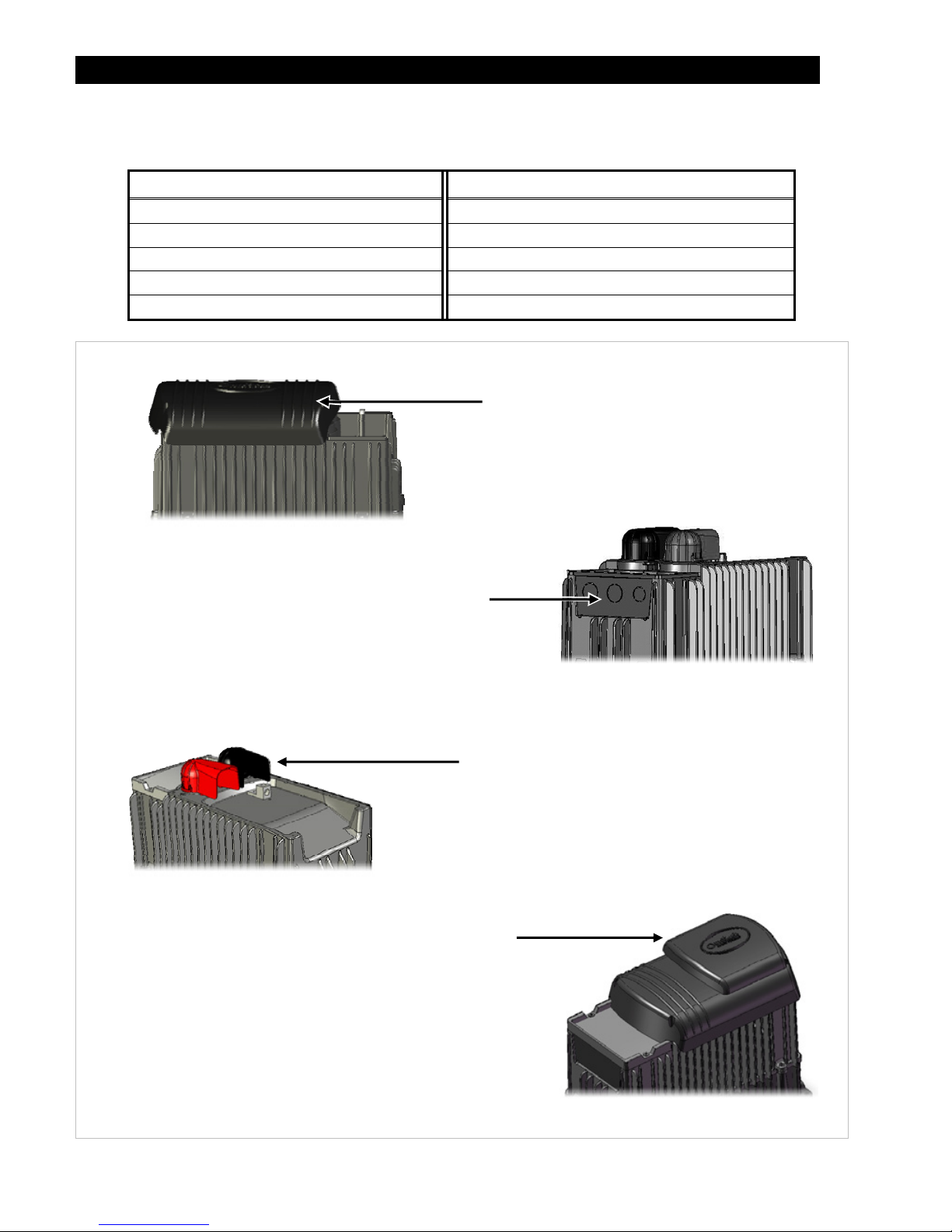
Figure 2 Components
DCC (DC Cover)
This covers the DC terminal area on vented inverters. The
DCC provides space to mount other components such as a
DC current shunt.
AC Plate
This plate is used for installations which do not utilize OutBack’s
optional FLEXware conduit boxes. The knockouts are used to
install strain relief for flexible cable.
NOTE: This plate is not to be connected to conduit.
Battery Terminal Cover
These protect the terminals from accidental contact. They are
made of stiff plastic with a snap-on design.
Always keep covers installed during operation.
Turbo Fan Cover
Included in place of the DCC on sealed inverters. Convectively cools
chassis with the external OutBack Turbo Fan to allow maximum power.
NOTE: Do not install the Turbo Fan on a vented inverter.
NOTE: The DC Cover or Turbo Fan does not replace the battery terminal
covers. These covers must be installed in addition to the DCC or fan.
900-0197-01-00 Rev A 9
Planning
Applications
OutBack inverter/chargers are designed to use a battery bank to store energy. In shore-based mobile and
marine connections, the shore power is used as the primary source. When the shore power is removed,
the inverter takes over to run the loads from the batteries. The settings can be changed to accommodate
many applications. Changes are made with the system display.
Mobile FX inverter/chargers work together with power from the utility grid (shore power), generator,
vehicle alternator, and/or renewable energy sources such as photovoltaic (PV) modules. When not using
the batteries, the inverter can charge it from an AC source. The alternator, PV harvest, or other DC sources
can also be used to recharge the batteries.
The FX inverter has one set of terminals for a single AC source. However, it can use two AC sources when
an external transfer switch is installed. The inverter can be independently programmed for each source. It
is common to use shore power and an AC generator. Other combinations of AC sources are possible.
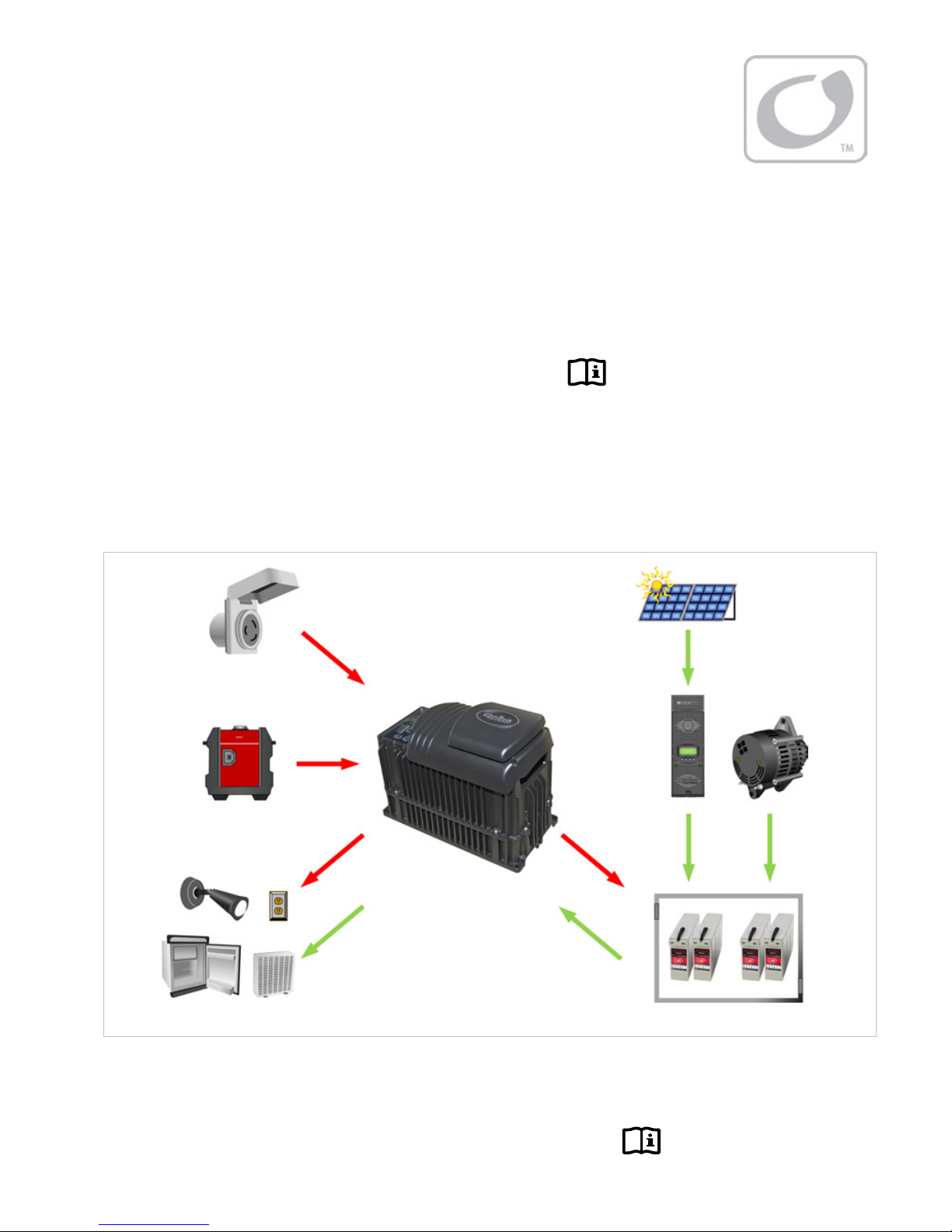
Figure 3 Applications (Example)
Programming
Selection of all inverter programming is performed using a system display such as the MATE, MATE2, or
MATE3. The system display can customize a wide range of parameters.
AC IN
o
r
Loads
AC OUT
PV Arra
y
or
DC IN
Shore
Power
or
DC OUT
or
AC Generator
Charge
Controller
Battery
Bank
Alternator
Mobile FX or VFX
Inverter/Charger
Planning
10
900-0197-01-00 Rev A
Renewable Energy
The inverter cannot connect directly to PV, alternators, or other DC sources. The batteries are the
inverter’s primary source of power. However, if the DC sources are used to charge the batteries, the
inverter can use their energy by drawing it from the batteries.
A renewable source is always treated as a battery charger, even if all of its power is used immediately.
The renewable source must have a charge controller, or some other regulation method, to prevent
overcharging. OutBack Power’s FLEXmax family of charge controllers can be used for this purpose, as
can other products.
Battery Bank
When planning a battery bank, consider the following:
Cables: Recommendations for battery cable size and length are shown on page 18. The maximum length will
determine the placement of the battery bank. Local codes or regulations may apply and will take priority over
OutBack recommendations.
Battery Type: The FX inverter/charger uses a three-stage charge cycle.
~The cycle was designed for lead-chemistry batteries intended for deep discharge. These include batteries for RV, marine,
golf-cart, and forklift applications. They also include gel-cell batteries and absorbed glass-mat (AGM) batteries. OutBack
Power recommends the use of batteries designed specifically for renewable energy applications. Automotive batteries
are strongly discouraged and will have a short life if used in inverter applications.
~Lithium-based batteries and other advanced battery technologies may require special considerations. Please contact
OutBack Technical Support at +1.360.618.4363 before implanting advanced technologies.
Nominal Voltage: These inverters are designed to work with specific battery bank voltages, which are different
depending on inverter model. Before constructing a battery bank, check the inverter model and confirm
nominal battery voltage.
Charger Settings and Maintenance: A vented battery enclosure may be required by electric code and is
usually recommended for safety reasons. It may be necessary to use a fan to ventilate the battery enclosure.
Batteries must be regularly maintained according to the instructions of the battery manufacturer.
IMPORTANT:
Battery charger settings need to be correct for a given battery type. Always follow
battery manufacturer recommendations. Making incorrect settings, or leaving them at
factory default settings, may cause the batteries to be undercharged or overcharged.
CAUTION: Hazard to Equipment
Batteries can emit vapors which are corrosive over long periods of time. Installing
the inverter in the battery compartment may cause corrosion which is not covered
by the product warranty. (Sealed batteries may be an exception.)
Bank Size: Battery bank capacity is measured in amp-hours. Determine the required bank specifications as
accurately as possible, beginning with the items below. This avoids underperformance or wasted capacity.
These ten items are obtainable in different places, summarized in Table 2 on the next page. Some of the
information is specific to the site or application. Some can be obtained from the battery manufacturer.
Information on OutBack products is available from OutBack Power Technologies or its dealers.
A. Size of load:
B. Daily hours of use:
C. Days of autonomy:
D. Application: This often helps define or prioritize the previous three items. Off-grid systems often require enough
capacity to last for an extended period before recharging. Grid-connected systems frequently need only enough
capacity for short-term backup during outages.
These are the most basic and
essential factors used to
determine bank size.
Planning
900-0197-01-00 Rev A 11
E. Conductor efficiency: Wire size and other factors will waste
power due to resistance and voltage drop. Typical
acceptable efficiency is 96 to 99%.
F. Inverter efficiency: FX specifications list “Typical Efficiency”
to help estimate operating loss.
G. System DC voltage: Each inverter model requires a specific DC voltage to operate.
H. Battery voltage: Most individual battery voltages are less than the system DC voltage. The batteries may need to be
placed in series to deliver the correct voltage.
I. Capacity: Battery capacity, which is measured in
amp-hours, is not usually a fixed number. It is
specified based on the rate of discharge. For example,
the OutBack EnergyCell 200RE is rated at 134.5 Ahr
when discharged at the 5-hour rate (to terminal
voltage 1.85 Vpc). This is a high rate of discharge that
would hypothetically drain the battery in 5 hours.
The same battery is rated at 191 Ahr when used at the
100-hour rate. Use the appropriate discharge rate
(correlated to the expected loads) to measure the
capacity of a battery. Use battery specifications for
terminal voltage 1.85 Vpc whenever possible.
NOTE: Capacity ratings are for batteries at 25°C.
Capacity is reduced at cooler temperatures.
J. Maximum depth of discharge (DoD): Most batteries cannot be discharged below a certain level without damage. The
bank requires enough total capacity to keep this from happening.
To Calculate Minimum Battery Bank Size (refer to Table 2 for letter designations):
1. The load size, item A, is measured in watts. Compensate this figure for efficiency loss. Multiply the
conductor efficiency by the inverter efficiency (E x F). (These items are represented as percentages, but
may be displayed as decimals for calculation.) Divide item A by the result.
2. Convert the compensated load into amperes (Adc). Divide the step 1result by the system voltage (item G).
3. Determine the daily load consumption in ampere-hours (amp-hours, or Ahr). Multiply the step 2result by
the daily usage hours (item B).
4. Adjust the total for required days of autonomy (the days the system must operate without recharging)
and the maximum DoD. Multiply the step 3result by C and divide by J.
The result is the total amp-hour capacity required for the battery bank.
5. Determine the number of parallel battery strings required. Divide the Ahr figure from step 4by the
individual battery capacity (I). Round the result to the next highest whole number.
6. Determine the total number of batteries required. Divide the system voltage by the battery voltage
(G ÷ H). Multiply the result by the step 5result.
The result is the total required quantity of the chosen battery model.
EXAMPLE #1
A. Loads: 0.5 kW (500 W)
B. Hours of use: 6
C. Days of autonomy: 1
D. Grid-interactive system (FX2012MT inverter)
E. Conductor efficiency: 98% (0.98)
F. Inverter efficiency: 90% (0.9)
G. System voltage: 12 Vdc
H. Batteries: OutBack EnergyCell 200RE (12 Vdc)
I. Capacity at 8-hour rate: 148.8 Ahr
J. Maximum DoD: 80% (0.8)
Any losses are essentially amp-hour
capacity that the system cannot use. The
battery bank size can be increased to
account for losses.
1) A ÷ [E x F] 500 ÷ (0.98 x 0.9) = 566.9 W
2) 1÷ G 566.9 ÷ 12 = 47.2 Adc
3) 2× B 47.2 × 6 = 283.4 Ahr
4) [3× C] ÷ J [283.4 × 1] ÷ 0.8 = 354.3 Ahr
5) 4÷ I 354.3 ÷ 148.8 = 2.38 (rounded to 3)
6) [G ÷ H] × 5[12 ÷ 12] × 3 strings = 3 batteries
Table 2 Battery Bank Elements
Item Source of information
A. Load Size Site-specific
B. Daily Hours Site-specific
C. Days of Autonomy Site-specific
D. Application Site-specific
E. Conductor Efficiency Site-specific
F. Inverter Efficiency Inverter manufacturer
G. System Vdc Inverter manufacturer
H. Battery Vdc Battery manufacturer
I. Capacity Battery manufacturer
J. Maximum DoD Battery manufacturer

Planning
12
900-0197-01-00 Rev A
EXAMPLE #2
A. Loads: 1 kW (1000 W)
B. Hours of use: 3
C. Days of autonomy: 1
D. Off-grid system (FX3048MT inverter)
E. Conductor efficiency: 97% (0.97)
F. Inverter efficiency: 93% (0.93)
G. System voltage: 48 Vdc
H. Batteries: OutBack EnergyCell 200RE (12 Vdc)
I. Capacity at 8-hour rate: 148.8 Ahr
J. Maximum DoD: 50% (0.5)
Generator
The FX inverter can accept single-phase input from a generator that delivers clean AC power in the range of
voltage and frequency specified for that model.
~Inverters stacked for split-phase output (120/240 Vac) can work with both output lines of a split-phase generator.
See pages 30, 32, and 36.
~Inverters stacked for three-phase output can work with three-phase generators. See page 38.
The inverter/charger can provide a start signal to control an automatic start generator. If automatic generator
starting is required, the generator must be an electric-start model with automatic choke. It should have two-wire
start capability. For other configurations, additional equipment may be required.
In any configuration, the inverter may need to be specifically programmed using the system display.
Perform all programming according to the specifications of the generator and the required operation of the
inverter. Parameters to be programmed may include generator size, automatic starting requirements, and
potential fluctuations in generator AC voltage.
Mobile generators are usually equipped with a bond between the neutral and ground connections. Mobile FX
inverter models have neutral-ground switching. This function establishes a bond on the inverter when no
generator is present, but removes it when the generator is running. See page 15 for more information on
neutral-ground bonding.
Generator Sizing
A generator should be sized to provide enough power for all the loads and the battery charger.
The generator size should assume maximum loads and maximum charging at the same time.
Available generator power may be limited by ratings for circuit breakers and/or generator connectors.
The generator must be able to provide current to all inverters on a given phase or output. Minimum generator
size
3
is usually recommended to be twice the power of the inverter system. For example, a 2 kVA inverter should
have a 4 kVA (or larger) generator. Many generators may not be able to maintain AC voltage or frequency for
long periods of time if they are loaded more than 80% of rated capacity.
In addition, if a split-phase 120/240 Vac generator is powering a single-phase 120 Vac inverter system with no
other compensation, it is required to be at least twice the power of the inverters. A split-phase generator that is
heavily loaded on one output line may suffer severely from balancing issues. The OutBack FW-X240 or PSX-240
balancing transformers may compensate for this condition.
IMPORTANT:
In general, the generator output should match the stacking and output of the inverters.
A three-phase generator should not be used with a 120/240 Vac inverter system.
A purely 240 Vac generator will cause damage if used with a 120 Vac inverter system.
3
This is the generator size after derating for environment, use, and other factors.
1) A ÷ [E x F] 1000 ÷ (0.97 x 0.93) = 1108.5 W
2) 1÷ G 1108.5 ÷ 48 = 23.1 Adc
3) 2x B 23.1 x 3 = 69.3 Ahr
4) [3x C] ÷ J [69.3 x 1] ÷ 0.5 = 138.6 Ahr
5) 4÷ I 138.6 ÷ 148.8 = 0.93 (rounded to 1)
6) [G ÷ H] x 5[48 ÷ 12] x 1 strings = 4 batteries

900-0197-01-00 Rev A 13
Installation
Location and Environmental Requirements
Sealed (FX) models are resistant to water and other elements but are not designed for permanent outdoor
installations. If installation on the outside of a vehicle is required, the FX inverter must be installed under
cover and protected from direct exposure to the environment. Vented (VFX) models are not resistant to
water and other elements. They must be installed in a weather-proof enclosure or enclosed area.
The inverter can often be mounted in any position or orientation. If there is any exposure to moisture or
condensation, the inverter must not be mounted upside-down. This ensures that water will not accumulate
under the DC cover. However, it can still be mounted in other positions or orientations.
For installations where the inverter may be exposed to moisture or condensation, a sealed model must be used
and mounted either with the base down (shelf mounting) or with the AC wiring compartment facing down
(wall mounting). If mounted with the base down, water cannot be allowed to accumulate around the inverter’s
base. There is a drainage system on the base of the inverter to dispel condensation. If submerged, water can
enter this drain and cause failure.
Vented inverters must be installed in a weather-proof enclosure or enclosed area. These models are not
designed for exposure to water or excessive wind-blown dust and debris.
When inverters are installed with an OutBack FLEXpower system, the system must be installed in the upright
orientation due to the requirements of the circuit breakers.
Any inverter will perform more efficiently in locations offering plenty of air circulation. The recommended
minimum clearance is 2 inches (5 cm) on all sides of the inverter.
Any inverter will function to all of its specifications if operated in a range of –4°F to 122°F (–20°C to 50°C).
The inverter will function, but will not necessarily meet its specifications, if operated in a temperature range of
–0°F to 140°F (–40°C to 60°C). This is also the allowable temperature range for storage.
The FX series of inverters carry an Ingress Protection (IP) rating of 20 and a Relative Humidity (RH) rating of 93%
(non-condensing).
Inverter specifications are listed in the FX Mobile Series Inverter/Charger Operator’s Manual.
Tools Required
Wire cutters/strippers
Torque wrenches
Assorted insulated screwdrivers
Digital voltmeter (DVM) or standard voltmeter
Installation
14
900-0197-01-00 Rev A
Mounting
One person can install the FX inverter, but installation may be easier with two people.
The unit has four mounting holes, one in each corner. Use fasteners in all corners for a secure installation.
IMPORTANT:
Use correct fasteners to secure the inverter to the mounting surface,
regardless of the type of surface. OutBack cannot be responsible for
damage to the product if it is attached with inadequate fasteners.
Due to the variance in other mounting methods, OutBack only endorses the use of FLEXware mounting
products or previous versions of OutBack mounting plates. Use M6 x 20 mm machine screws, one per corner,
to attach the inverter to the mounting plate. Follow the instructions with each mounting system.
Mount and secure each component before attaching any wiring.
When the inverter is used with other metal chassis, make sure that all chassis are grounded appropriately.
(See the grounding instructions on page 15.) Grounding other chassis may involve metal-to-metal contact, or
separate ground wires.
If using an OutBack FLEXware Mounting Plate, avoid large air gaps behind the plate. These can result in
louder mechanical noise during heavy inverting or charging. Mount the plate on a flat, solid
mounting surface.
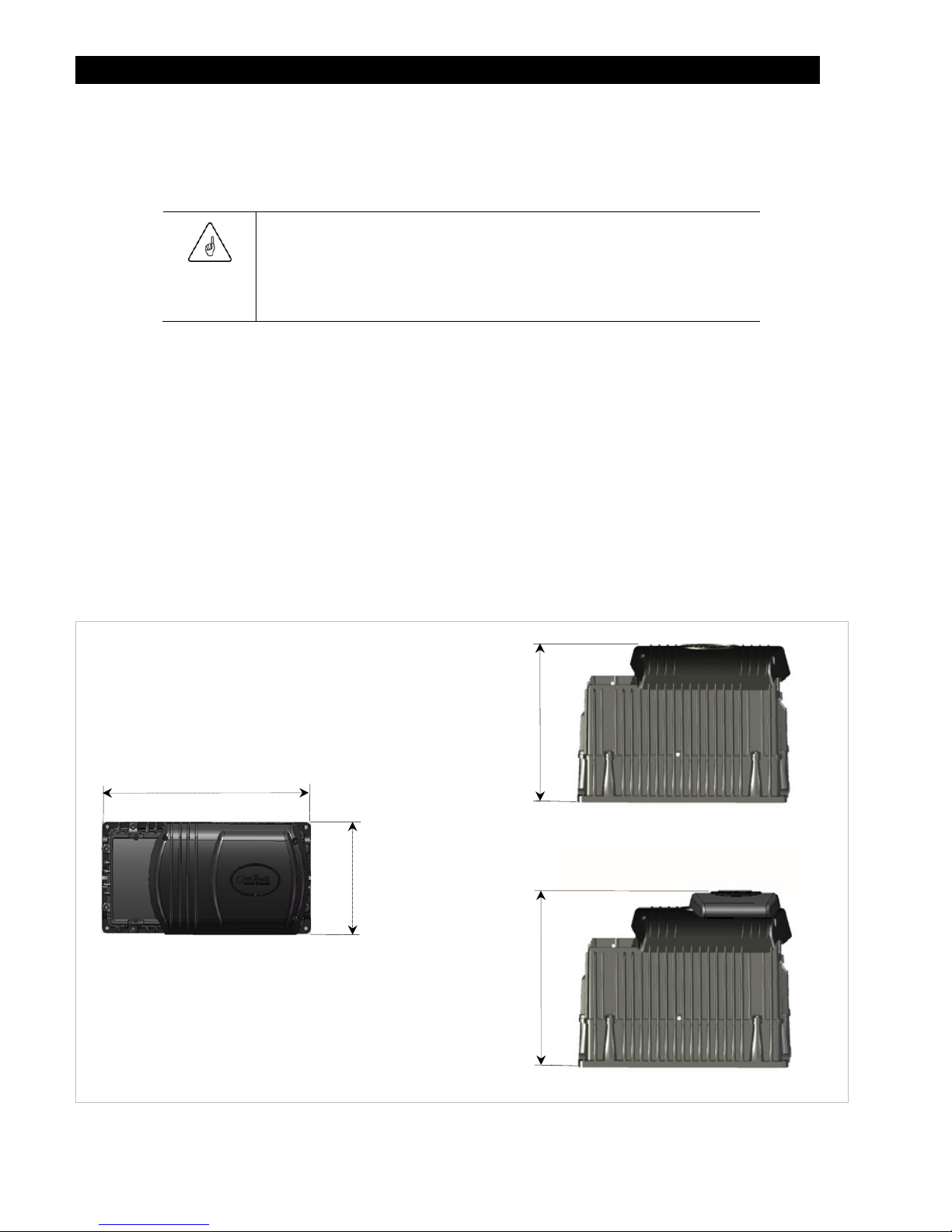
Dimensions
Figure 4 Dimensions
Height
with Turbo
13” (33 cm)
Width
8.25” (21 cm)
Length 16.25” (41 cm)
Height
without
Turbo
12” (30.5 cm)

Installation
900-0197-01-00 Rev A
15
Terminals and Ports
Figure 5 Terminals, Ports, and Features
WARNING: Shock Hazard
The inverter’s AC output is defaulted to ON from the factory. It will deliver AC voltage as
soon as the power is connected.
DC and AC
GROUND TERMINALS
These terminals connect to
a grounding system for
both batteries and AC. See
page 15 for instructions.
INVERTER ON/OFF
These terminals receive wires for a manual on/off
switch to control the inverter.
ON/OFF JUMPER
The jumper alongside these terminals overrides
them and turns the inverter on. (See page 23 for
instructions.) With the jumper installed, a switch
cannot turn the inverter off, but the system
display can turn it off or on. The system display
cannot turn it on if the jumper is not installed.
DC TERMINALS
These terminals connect to the
battery cables and the DC system.
See page 18 for instructions.
CONTROL WIRING TERMINAL BLOCK
These terminals receive control wires for a
variety of functions including generator control.
See pages 24 and 25 for instructions and the
Operator’s Manual for more information.
The Terminal Block can be unplugged from the
AC board for convenience. While installed, keep
screws tight and the block itself secured tightly
to the AC board to prevent malfunction. XCT+/XCT-
Non-operational terminals.
Do not connect anything
to them.
MATE/HUB and RTS PORTS
These ports receive the RJ45
and RJ11 plugs from the
system display and Remote
Temp Sensor. See page 23
for instructions.
The ports are mounted
sideways. When viewed
from the left side, they
appear as shown below.
AC TERMINAL BLOCK
These terminals receive AC
input and output wires. See
page 21 for instructions.
LED INDICATORS
These indicators display the inverter status and battery voltage.
The three BATTERY LED indicators (green, yellow, and red) are based on
DC voltage, and provide a very general idea of battery state.
The green INVERTER LED indicator shows if the inverting function is on.
The yellow AC IN LED indicator shows if an AC source is present.
The red ERROR LED indicator shows either a Warning or an Error. A
Warning is an alert for a problem that is not severe enough for
shutdown. An Error usually accompanies inverter shutdown.
AUX OUTPUT (AUX+/AUX-)
These terminals deliver 12 Vdc up to 0.7 amps
(8.4 watts). The output can be switched on and
off for many functions. The default function is to
drive a cooling fan or the Turbo Fan.
See page 24 for details.
The functions for the AUX output can be
programmed using the system display. AUX LED INDICATOR
Orange LED indicator turns on when
12 Vdc output is present.
Installation
16
900-0197-01-00 Rev A
Wiring
It will be necessary to remove knockouts from the AC Plate to run wires. The AC Plate has one knockout of
½” size and two knockouts of ¾” size. Install appropriate bushings to protect the wires.
Use copper wire only. Wire must be rated at 75°C or higher.
Grounding
WARNING: Shock Hazard
Mobile models perform automatic neutral-to-ground bond switching. When this
function is engaged, the chassis ground is electrically common with the output
neutral conductor. When disengaged, the chassis ground is isolated from the AC
system. See pages 17, 21, and 22.
Make sure that no more than one bond is present in the AC system at any time.
WARNING: Shock Hazard
For all installations, the negative battery conductor should be bonded to the grounding
system at only one point. If the OutBack GFDI is present, it can provide the bond.
IMPORTANT:
Not all OutBack products can be used in a positive-ground system. If it is necessary to
build a positive-ground system with OutBack products, contact OutBack Technical
Support at +1.360.618.4363 before proceeding. Additionally, consult the online forum
at www.outbackpower.com/forum/, where this subject has been discussed extensively.
Table 3 Ground Conductor Size and Torque Requirements
Terminal Location Minimum Conductor Size Torque Requirements
Central AC Terminals #10 AWG (0.009 in) or 6 mm 25 in-lb (2.8 Nm)
DC Box Lug #6 AWG (0.025 in) or 16 mm 45 in-lb (5.1 Nm)
Table 3 contains OutBack’s recommendations for minimum safe cable sizes. Other codes for mobile
or marine applications may supersede OutBack’s recommendations. Consult applicable codes for final
size requirements.

Installation
900-0197-01-00 Rev A 17
The inverter’s DC ground is a box lug located next to the negative DC battery terminal. This lug accepts
up to 1/0 AWG (70 mm or 0.109 in) wire. Local codes or regulations may require the DC ground to be run
separately from the AC ground. Also, if present, it will be necessary to remove the DC Cover or Turbo Fan
before making the ground connection. (See page 20.)
Figure 6 DC Ground Lug
Figure 7 Chassis Ground
Box Lug
One ground terminal is labeled CHASSIS GROUND.
This terminal connects to an external ground bar or
bus. The other terminal, labeled NEU/GROUND BOND,
is not common with CHASSIS GROUND, but is joined
to it by a copper jumper. No external connection is
made to NEU/GROUND BOND.
As long as the copper jumper is present, the FX
inverter will automatically perform neutral-ground
bond switching.
If removed, the inverter’s neutral and ground will
be isolated.
If only one mobile inverter is present, leave the
copper jumper in place.
If more than one mobile inverter is present, remove
the copper jumper from every Slave unit.
See the inverter Operator’s Manual for the general
operation of neutral-ground bond switching.
See page 22 for more information on the inverter’s
switching function.
Installation
18
900-0197-01-00 Rev A
DC Wiring
WARNING: Shock Hazard
Use caution when working in the vicinity of the inverter’s battery terminals.
CAUTION: Equipment Damage
Never reverse the polarity of the battery cables. Always ensure correct polarity.
CAUTION: Fire Hazard
The installer is responsible for providing overcurrent protection.
Install a circuit breaker or overcurrent device on each DC positive (+)
conductor to protect the DC system.
Never install extra washers or hardware between the mounting surface
and the battery cable lug. The decreased surface area can build up heat.
See the hardware diagram on page 19.
IMPORTANT:
The DC terminals must be encased in an enclosure to meet the requirements
of some local or national codes.
Table 4 contains OutBack’s recommendations for minimum safe cable sizes.
Other codes may supersede OutBack’s recommendations. Consult applicable
codes for final size requirements.
Table 4 DC Conductor Size and Torque Requirements
Inverter
(Wattage/Voltage)
Nominal DC Amps
(Derated 125%)
Conductor Size
4
(Minimum)
Breaker Size
(Minimum)
FX2012MT 200 4/0 AWG (120 mm) or 0.186 in 250 Adc
FX2024M 100 2/0 AWG (70 mm) or 0.109 in 175 Adc
FX2524MT 125 2/0 AWG (70 mm) or 0.109 in 175 Adc
FX2532MT 94 1/0 AWG (70 mm) or 0.109 in 125 Adc
FX2536MT 83 1/0 AWG (70 mm) or 0.109 in 125 Adc
FX3048MT 75 1/0 AWG (70 mm) or 0.109 in 125 Adc
VFX2812M 280 4/0 AWG (120 mm) or 0.186 in 300 Adc
VFX3524M 175 4/0 AWG (120 mm) or 0.186 in 175 Adc
VFX3232M 120 2/0 AWG (70 mm) or 0.109 in 175 Adc
VFX3236M 107 2/0 AWG (70 mm) or 0.109 in 175 Adc
VFX3648M 90 1/0 AWG (70 mm) or 0.109 in 125 Adc
Terminal Location Torque Requirements
Inverter DC Terminals 60 in-lb (6.9 Nm)
Battery Terminals See battery manufacturer’s recommendations
When installing DC cables:
Battery positive and negative cables should be no longer than 10 feet (3 meters) each, to minimize voltage loss
and other possible effects.
Turn off DC circuit breakers or remove fuses before proceeding.
Tie, tape, or twist cables together to reduce self-inductance. Run positive and negative cables through the same
knockouts and conduit.
The inverter’s battery terminal is a threaded stud which accepts a ring terminal lug. Use crimped and sealed
copper ring lugs with 5/16 inch (0.79 cm) holes, or use compression lugs.
Install all overcurrent devices on the positive cable.
4
Cable sizes are for each inverter in a system. In a system with multiple inverters, each inverter requires its own cables and overcurrent devices of
the size indicated.

Installation
900-0197-01-00 Rev A 19
To install DC cables and hardware:
1. Install all DC cables.
Do not install hardware in a different order from Figure 8. The battery cable lug should be the first item
installed on the stud. It should make solid contact with the mounting surface.
Do not close the main DC disconnect until wiring is complete and the system is prepared for commissioning.
Figure 8 Required Order of Battery Cable Hardware
CAUTION: Fire Hazard
Never install extra washers or hardware between the mounting surface and the
battery cable lug. The decreased surface area can build up heat.
2. Install the battery terminal covers. These are made of stiff plastic with a snap-on design.
Figure 9 Battery Terminal Covers
Mounting Surface
M8 x 1.25 Stud
Lock Washer
Battery Cable Lug
13 mm Nut
Flat Washer
Insulator
REMOVAL SLOT
If it is necessary to remove the covers, remove
carefully using a flat screwdriver.
Insert the screwdriver into the slot on the
side of each cover and unsnap the cover..
Installation
20
900-0197-01-00 Rev A
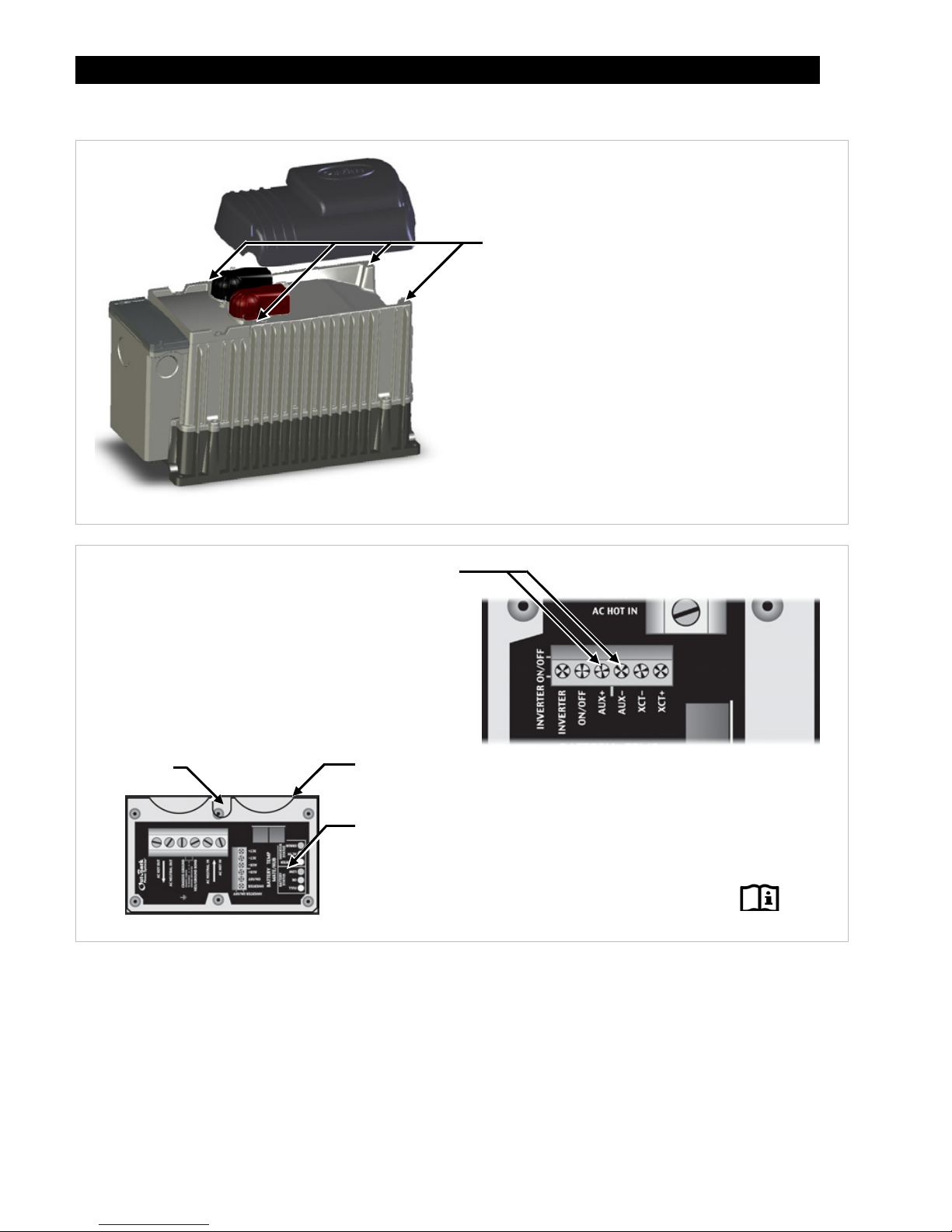
DC Cover or Turbo Fan Attachment
Figure 10 DC Cover Attachment
Figure 11 Turbo Fan Wiring
If it is necessary to remove the Turbo Fan:
1. Remove the compartment cover.
2. Unscrew the AUX+ and AUX– terminal screws.
3. Remove the wires.
4. Remove the screws at the four corners of the Turbo Fan.
5. Remove the Turbo Fan.
COVER ATTACHMENT
FX inverters are equipped with either the DC
Cover or the Turbo Fan.
To attach either cover, put the cover in place.
Insert a screw at each corner using a
Phillips screwdriver.
As part of attaching the Turbo Fan, follow the
wiring instructions in Figure 11.
TURBO FAN WIRING
Install the wires in the AC Wiring Compartment to
make the Turbo Fan operational. The AUX+ and
AUX– terminals receive the red (+) and black (–)
wires. Tighten with a Phillips screwdriver.
To safely run the wires into the AC compartment,
pass the wires through the notch in the
compartment cover.
If necessary, the green terminal block can be unplugged
b
y
pulling it gentl
y
awa
y
from the AC board.
Make certain the AUX programming is
correct for proper fan operation.
Notch
Compartment
Edge of Cover
Other manuals for FX series
1
This manual suits for next models
1
Table of contents
Other Outback Inverter manuals


