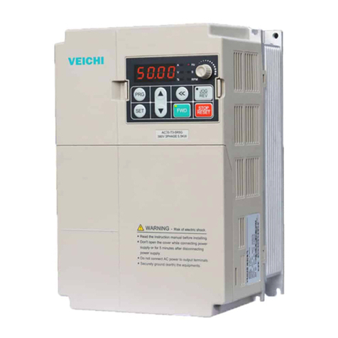
Veichi SD700-1R1A series User manual

1
Preface
Thank you for choosing SD700 series AC servo driver.
SD700 series AC servo driver is our general high-performance servo driver. This product adopts a series of
advanced motor control algorithms and 24 bits high precision encoder. It has the characteristics of high control precision,
fast tracking response, simple and convenient debugging. It can meet the function and performance of the high-end
servo application requirements. The product has built-in point control function, electronic cam, RS485 interface,
CANopen interface, 16 bit analog input and other rich application expansion functions. It can provide high reliability
and high cost performance solutions for machine tools, electronic equipment, robots, textiles, packaging and so on.
This manual only provides the introduction of safety precautions, installation and wiring, functional code sheets,
troubleshoot and countermeasures, and monitoring parameter description. Detailed functional annotations and
application notes refer to the SD700 series product manuals or consulting our company. This manual is the basic
guidance document for your proper use, giving full play to its superior performance and safe operation. Please read it
carefully and keep it properly, and hand it over to the end user of this product.
In the course of using, if you have any difficult problems or special requirements, please contact with our company
(Office) or distributor at any time. You can also contact our customer service center directly. We will serve you
wholeheartedly.
Our company has been committed to the continuous optimization of products. Therefore, this series of products and
related information may be optimized or changed, and there is possibility of change. If there is any change, no notice
will be given.
Safety precautions
To ensure the safe and reasonable use of this product, please use the product after fully understanding the safety
precautions described in this manual.
Operational qualification
This product must be operated by trained professionals. The operator must undergo professional skills training,
familiar with the installation, wiring, operation and maintenance of the equipment, and correctly deal with all kinds of
emergencies in use.
Safety guidance
The warning sign is for your safety. It is a measure to prevent operators from being injured and damage to this
product and associated system. Please read this manual carefully before use and strictly follow the safety rules and
warning signs in this manual.
Proper transportation, storage, installation and careful operation and maintenance are very important for the safe
operation of the servo system. During transportation and storage, the servo system must not be subjected to impact and
vibration, and must also be kept in dry, non corrosive gas, conductive dust and ambient temperature less than 60 degrees
Celsius.
This product has a dangerous voltage, and it is controlled by a potentially dangerous sports organization. If it fails
to comply with the regulations or does not comply with the requirements of this manual, it may lead to personal injury,
damage to the product and associated systems.
Do not connect with the power supply, otherwise you will be in danger of electrocution. When the wiring,
inspection, maintenance and other operations, please cut off the power of all associated devices, and confirm that the DC
voltage of the main circuit has dropped to a safe level, and then wait for 10 minutes to do the related work.
The power line, motor line and control line must be fastened and connected. The earthing terminals must be

2
reliably grounded and the earth resistance is less than 10 ohms.
The static electricity of the body will seriously damage the internal sensitive devices. Before conducting related
operations, please comply with the measures and methods stipulated in the electrostatic prevention measure (ESD),
otherwise it may damage the servo system.
Since the output voltage of the servo system is a pulse waveform, if the output side is equipped with a capacitor
for improving the power factor or a varistor for lightning protection, it is necessary to dismantle or refit the input side of
the servo system.
No switching devices such as circuit breakers and contactors should be added to the output side of the servo
system. If the switch device must be connected to the output side, the output current of the servo system must be
guaranteed to be zero when controlling the switch.
No matter where the fault occurs in the control equipment, it is possible to stop production and major accidents.
Therefore, please select the necessary external protective measures or stanDBy devices.
This product can only be used in accordance with the purpose specified by the manufacturer, and shall not be
used in special fields such as emergency, rescue, shipping, medical, aviation, nuclear facilities, etc. without permission.
The maintenance of this product can only be carried out by our company or the professional licensed by the
company. Unauthorized modification and use of non company accessories may result in product failure. Any defective
device must be replaced in time.

3
1. Installation and wiring
1.1. Installation dimension
W
H
DW1
H1
B
A
安装孔径
W2
Struct
ure Machine model
Outline size (mm)
Installation dimension (mm) Inst
alla
tion
aper
ture
W H D W1 W2 H1 A B
SIZE A
SD700-1R1A-**
45 168 170 \ 20 160 7.5 5 2-M4 SD700-1R8A-**
SD700-3R3A-**
SIZE B
SD700-5R5A-**
71 168 180 58 58 160 6.5 5 3-M4
SD700-7R6A-**
SD700-9R5A-**
SD700-2R5D-**
SD700-3R8D-**
SIZE C
SD700-160A-**
92.5 188 182 82.5 75 180 5 5 3-M4
SD700-6R0D-**
SD700-8R4D-**
SD700-110D-**
SIZE D
SD700-170D-**
120 260 210 100 84.5 250 10 7.2 4-M5 SD700-240D-**
SD700-300D-**

4
Structure Machine model Outline size (mm) Installation dimension (mm) Installation
aperture
W H D W1 W2 H1 H2
SIZE E SD700-500D-** 210 471 254 140 140 457 434.5 4-M6
SD700-600D-**
SIZE F
SD700-700D-**
240 558 310 176 176 544 520 4-M6
SD700-800D-**
SD700-121D-**
1.2. Main circuit terminal size
L1
L2
L3
L1C
L2C
B1
B2
B3
U
V
W
+
/
Main circuit interface
Needle
number
Signal
name Function
1 L1(R) Main circuit power input
Please confirm whether the input power is 220V or 400V according to the
nameplate.
220V model: 200V ~ 240V, -15% ~ +10% 50/60Hz
400V model: 380V ~ 440V, -15% ~ +10% 50/60Hz
Note: "L3" terminals, SD700-1R1A, 1R8A and 3R3A models are single-phase
input without this pin.
2 L2(S)
3 L3(T)
4 L1C Control power input

5
5 L2C The power input requirements are same with L1, L2 and L3.
6 B1/+ Regenerative resistor connection terminal
When SD700-1R1A, 1R8A and 3R3A have insufficient regenerative braking
capability, they connect external regenerative resistors between B1/+
and B2. The other models remove the short or short connections between
B2-B3, connect external regenerative resistors between B1/+ and B2, and
purchase external regenerative resistors.
The "B1/+" terminal can be used for common DC bus positive power
terminals.
Note: "B3" terminals, SD700-1R1A, 1R8A and 3R3A do not have this pin.
7 B2(PB)
8 B3
9 - "-" terminals can be used for common DC bus negative power terminals.
10 U
Connect U, V and W phases of motor 11 V
12 W
13 Safely
1.3. CN1 control end word
1.4. Cn2 encoder signal terminal

6
Note: when using the multi loop absolute encoder, pay attentiontothe
connectionofbatteryandserialdata.
1.5. Motor power terminal

7
110/130/180flange(E2,D2)motorpowerlinedefinition
Signal definition Foot position
number
Core color
U D blue
V E Brown
W F red
PE G Yellow green
BAKE+ A red
BAKE+ B black
1.6. CN6A/CN6B bus communication terminal
Accordingtothedifferentmodels,thedefinitionoftheportisdifferent,andthedefinitionoftheinterface
shouldbeconfirmedafterusingthemodel.
ThefieldidentificationbitisP:pulsetype;S:standardtype;C:CANopenbustype.
CN6A/CN6B interface definition
Needle
number Signal name
Function Needle number
Signal name
Function
1 CANH Can data + 6 -
2 CANL Can data - 7 GND 485 signal
ground
3 CANG Can signal
ground 8 - -
4 485- 485 data - Shell Shield Shield
5 485+ 485 data +
ThefieldidentificationbitisM:
MECHATROLINK‐IIbustype.
CN6A/CN6B interface definition
Needle
number Signal name function
1 SRD+ M-II data + 6 - -
AC
D
E
F
GI H
B

8
2 SRD- M-II data - 7 - -
3 - - 8 - -
4 - - Shell Shield Shield
5 - -
ThefieldidentificationbitisN:EtherCATbustype;L:MECHATROLINK‐IIIbustype.
CN6A/CN6B interface definition
Needle
number Signal name
function Needle number
Signal name
function
1 TX+ Data sending +
6 RX- Data reception -
2 TX- Data
transmission -
7 - -
3 RX+ Data reception +
8 - -
4 - - Shell Shield Shield
5 - -
Regarding the simultaneous use of multiple drives, the cascading mode is CN6A input and CN6B out. The
cascaded cable is below 50cm, and the last CN6B must connect the terminal resistance as the case may be.
1.7. Keyboard and function
Key name Key function
MODE/SET key
Key for function mode switching
Key for parameter setting confirmation
Key for auxiliary function execution
▲ UP key It is used to select parameters or increase numeric values. For multi segment display, the
parameters can be used to switch high, middle and low segment values.
DOWN key It can be used to select parameters or reduce numerical values. The parameters for multi segment
display can be used to switch high, middle and low segment values.
DATA/SHIFT
key
Press the data/shift key for about 1 seconds to enter or exit.
Short press for left shift one bit (blinking)
Note: holding the UP key and the DOWN key at the same time can reset the servo alarm. Before the servo alarm is reset, it is necessary to
MODE
SET
DATA

9
exclude the cause of the alarm.
1.8. Output port considerations
1.9. Brake wiring
When the servomotor is used for the vertical axis, the brake can be used to prevent or maintain
the speed of the falling of the weight when the servo driver is cut off.
The 24V power supply for electromagnetic brake requires a special power supply from users.
Do not share the power with the control signal.
The relay coil is shown in the picture. Please note the direction of the diode.
The electromagnetic brake is used for maintenance and can not be used for normal parking.
Although the electromagnetic brake has the function of preventing or maintaining the
falling of heavy objects, users are required to install brake devices externally.
RY

10
1.10. Example of location control connection

11
1.11. Example of speed control connection

12
1.12. Example of torque control connection

13
2. Testing Running
2.1. Jog trial run
The purpose of the jog trial operation is to confirm whether the servo unit and the servo motor are properly
connected and whether the servo motor is operating normally.
Pn500 set the point speed (default value is 500rpm).
Pn310 set point acceleration time (default value 0ms).
Pn311 set the dynamic deceleration time (default value 0ms).
Parameter settings panel operation can refer to the Pn group parameter setting method.
Parameter Pn group setting method: take the setting method of speed loop gain (Pn101) from 40 to 100 for example.
After the parameter settings are completed, perform auxiliary function Fn005, panel operation steps:
2.2. Bandwidth setting (Fn303)

14
2.3 Restore factory parameters (Fn003)
2.4 Automatic adjustment of instruction bias (Fn100)
The servo off inputs 0V instruction voltage from the upperdeviceortheexternal
loop.
2.5 Current bias automatic adjustment (Fn103)

15
3 Functional code list
3.1 Group Pn0 basic control
Function
code Parameter name Range Default value Company Postal
address
Effective
way
Pn000
Control mode selection 0~11 0 - 0x0000
Power
failure
effective
0- position mode 1- analog speed 2- torque mode 3- internal speed 4- internal speed < > analog speed
5- internal speed < > position mode 6- internal speed < > torque mode 7- position mode < > analog speed
8- position mode < > torque mode 9- torque mode < > analog speed.
10- analog speed < < zero bit function speed mode 11- position mode < > position mode forbidden by instruction pulse.
Pn001
Internal enable 0~1 0 - 0x0001 Immediate
effect
0- enables 0ff 1- to enable on
Pn002
Motor rotation direction selection 0~1 0 - 0x0002
Power
failure
effective
Facing the motor end face: 0- is clockwise positive 1- and clockwise direction is positive.
Pn003
Default monitoring parameters 0x0~0xfff 0xfff - 0x0003 Immediate
effect
Set up the default monitoring parameters after power up, set the value to see the monitoring parameters in detail, 0xfff
indicates that the monitoring parameters are not displayed and the system status is displayed.
Pn004
Selection of stop methods for servo off
and first kinds of alerts 0~2 0 - 0x0004
Power
failure
effective
0- stops the motor 1- through DB, stops the motor through DB, then releases DB 2-, does not use DB, so that the
motor is in free motion state.
Pn005
Second types of alarm stopping
methods for servo selection 0x00~0x01 0 - 0x0005
Power
failure
effective
0- zero speed stop: set speed command to "0", execute fast stop 1- and Pn004 stop method same.
Pn006
Overrange warning detection selection 0~1 0 - 0x0006
Power
failure
effective
0- over limit warning is not detected when 1- limit is exceeded.
Pn007
Stop method selection for servo
override (OT) 0~2 0 - 0x0007
Power
failure
effective
0-Same with Pn004 stop method
1- Set the torque of Pn053 as the maximum value, slow down after shutdown and enter the locked state.
2- Takes the torque set by Pn053 as the maximum value, and then slows down and enters the free running state.
Pn008 Servo locking time after brake of
electromagnetic brake 0~50 0 10ms 0x0008 Immediate
effect

16
When the servomotor is enabled but not running and is in a stop state, when the brake (/BK) signal and the servo ON
(/S-ON) signal are OFF at the same time, setting this parameter can change the time of the brake signal (/BK) off to the
time when the motor is actually not in power.
Pn009
Brake delay of electromagnetic brake 10~100 50 10ms 0x0009 Immediate
effect
When the servo motor rotates in the servo OFF/, when the alarm / main circuit off occurs, the servomotor is not energized,
and the output time of the brake signal (/BK) OFF can be adjusted by this parameter and the braking delay time of the
brake (any one meet).
Pn010 Delay release speed of brake for
electromagnetic brake 0~10000 100 rpm 0x0010 Immediate
effect
Pn012 External regeneration resistance power 0~65535 0 10W 0x0012 Immediate
effect
Pn013 External regenerative resistance 0~65535 0 mΩ 0x0013 Immediate
effect
Pn015
Overload warning value 1~100 20 % 0x0015
Power
failure
effective
Setting this parameter can change the overload warning detection time, for example, the overload warning time at the
factory is 20% of the overload alarm detection time.
Pn016 Motor current overload detection base
current derating setting
10~100 100 % 0x0016 Power
failure
effective
Pn030 Retention parameter 0~65535 0 - 0x0030 Immediate
effect
Pn031
Parameter modification operation
locking 0~1 0 - 0x0031
Power
failure
effective
0- allows the panel to modify the parameter 1-. No panel modification parameters are allowed.
Function
code Parameter name Range Default value Company Postal
address
Effective
way
Pn040
The use of absolute encoder 0~1 0 - 0x0040
Power
failure
effective
0- uses absolute encoder as absolute value encoder 1- uses absolute encoder as incremental value encoder:
Pn041
Alarm / warning selection for absolute
encoder battery under voltage 0~1 0 - 0x0041
Power
failure
effective
0- sets the battery voltage low to 1- and sets the battery voltage low as a warning.
Pn044 Full closed loop application related
switch 0-51 1 - 0x0044
Power
failure
effective
The 0: encoder has pulse frequency output, the grating ruler power is effective, the grating ruler signal does not filter the
1: pulse output, the grating ruler power is effective, and the grating ruler signal is not filtered.
18: encoder pulse frequency output, grating scale power supply invalid, 0~4MHZ filter

17
19: grating ruler pulse output, grating scale power supply invalid, 0~4MHZ filtering
Pn045
Functional selection under voltage 0x00~0x02 0 - 0x0045
Power
failure
effective
0-does not detect the main circuit drop warning
1- detection of the main circuit drop warning 2- detection of the main circuit drop warning and torque limit.
Pn046
Torque limit during main circuit voltage
drop 0~100 50 % 0x0046 Immediate
effect
According to the under voltage warning, the torque limit is applied to the servo unit, as shown in the "torque limit under
voltage".
Pn047
Torque limit relief time for main circuit
voltage drop 0~1000 100 ms 0x0047 Immediate
effect
After the undervoltage warning is relieved, the torque limit value of the servo unit is controlled according to the setting time
servo.
Pn050
Torque limiting mode setting 0~3 1 - 0x0050 Immediate
effect
0 - analog torque (torque mode invalid)
1 - maximum torque limit 1
2 - positive maximum torque limit 1; reverse maximum torque limit 2
3 - Switching value "Torque limit switch" .When it is OFF: the maximum torque limit 1.When it is ON: the maximum
torque limit 2
Pn051 Maximum torque limit 1 0~500 500 % 0x0051 Immediate
effect
Pn052 Maximum torque limit 2 0~500 500 % 0x0052 Immediate
effect
Pn053 Emergency stop torque 0~800 800 % 0x0053 Immediate
effect
Pn061
Panel parameter display selection 0x00~0x01 1 - 0x0061
Power
failure
effective
0- only displays the settings parameter 1- to display all parameters.
Pn070
Encoder frequency division pulse count 16~4194304 2048 - 0x0070
Power
failure
effective
According to the setting value of the parameter, the number of pulses per cycle from the encoder is processed by frequency
division. Please set the system according to the specifications of the machine and the upper device.
Pn072
Frequency output inversion 0~1 0 - 0x0072
Power
failure
effective
The 0- pulse output is not reversed: when the forward turns, A is ahead of B 1- pulse output is reversed: when the forward
turns, B is ahead of A
Pn080 Local communication address 0x00~0x7F 1 - 0x0080
Power
failure
effective

18
Pn081
485 communication baud rate selection 0~4 1 - 0x0081
Power
failure
effective
0-9600bps 1-19200bps 2-38400bps 3-57600bps 4-115200bps
Pn082
485 communication check mode 0~5 1 - 0x0082
Power
failure
effective
0- no check (N, 8,1) 1- even parity check (E, 8,1) 2- odd parity check (O, 8,1) 3- no check (N, 8,2) 4- even parity
check (E, 8,2) 5-odd parity check(O,8,2)
Pn083
Baud rate selection for Canopen
communication 0~6 4 - 0x0083
Power
failure
effective
0: 20kbps 1: 50kbps 2: 100kbps 3: 125kbps 4:250kbps 5: 500kbps 6: 1000kbps
Pn085
Communication data storage EEPROM 0x0~0xFFF 0x1 - 0x0085
Power
failure
effective
Bit0: 0: stores data to Eeprom 1: and does not store data to Eeprom
Bit1: 0: is powered on, the value of Pn085 is coercion Bit0 is 1 1:. When the power on is activated, the value of Pn085 is
not forced to Bit0 1.
3.2 Group Pn1 gain class
Function
code Parameter name Range Default
value Company Postal
address
Effective
way
Pn100
Rotary inertia ratio 0~20000 100 % 0x0100 Immediat
e effect
Rotary inertia ratio = motor shaft conversion load inertia / servo motor rotor inertia *100%
Pn101
First speed gain 1~2000 40.0 Hz 0x0101 Immediat
e effect
Parameters that determine speed loop responsiveness. Because the response of the speed loop is low, it will become the
delay element of the outer position loop. Therefore, overshoot or speed instruction will be vibrated. The larger the setting
value is, the more stable the servo system and the better response will be.
Pn102
First velocity integral time constant 0.15~512 20.00 ms 0x0102 Immediat
e effect
In order to respond to the tiny input, the speed loop contains integral elements. Because the integral element is a delay
factor for the servo system, when the time parameter is set too large, the overshoot will occur, or the positioning time will
be prolonged, which will make the response worse.
Pn103
First position gain 1~2000 40.0 1/s 0x0103 Immediat
e effect
The response of the position loop is determined by the gain of the position loop. The higher the setting of the position
loop gain is, the higher the responsiveness and the shorter positioning time will be. The gain of the position loop can not
be raised beyond the rigidity of the mechanical system.
Pn104 First torque command filter 0~655.35 1.00 ms 0x0104 Immediat
e effect

19
Adjusting the parameters of the torque command filter may eliminate the vibration caused by the servo drive. The
smaller the value is, the better the response can be controlled, but it is restricted by the machine condition.
Pn105
Second speed gain 1~2000 40.0 Hz 0x0105 Immediat
e effect
Parameters that determine speed loop responsiveness. Because the response of the speed loop is low, it will become the
delay element of the outer position loop. Therefore, overshoot or speed instruction will be vibrated. The larger the setting
value is, the more stable the servo system and the better response will be.
Pn106
Second velocity integral time constant 0.15~512 20.00 ms 0x0106 Immediat
e effect
In order to respond to the tiny input, the speed loop contains integral elements. Because the integral element is a delay
factor for the servo system, when the time parameter is set too large, the overshoot will occur, or the positioning time will
be prolonged, which will make the response worse.
Pn107
Second position gain 1~2000 40.0 1/s 0x0107 Immediat
e effect
The response of the position loop is determined by the gain of the position loop. The higher the setting of the position
loop gain, the higher the responsiveness and the shorter the positioning time. The gain of the position loop can not be
raised beyond the rigidity of the mechanical system.
Pn108
Second torque command filter 0~655.35 1.00 ms 0x0108 Immediat
e effect
Adjusting the parameters of the torque command filter may eliminate the vibration caused by the servo drive. The
smaller the value, the better the response can be controlled, but it is restricted by the machine condition.
Pn110
Gain switching mode selector switch 0x00~0x01 0 - 0x0110 Immediat
e effect
0- Manual gain switching by external input signal (G-SEL).
1- automatic switching condition is established (Pn111), automatically switching from first gain to second gain,
otherwise, switch back to first gain.
Pn111
Condition control gain automatic
switching condition 0x00~0x05 0 - 0x0111 Immediat
e effect
0-positioning complete signal ON 1- positioning completion signal OFF 2- positioning close to signal ON
3- positioning close to signal OFF 4- Zero after position command filtering and pulse input OFF
5- position instruction pulse input OFF
If the condition is satisfied, switch to second gain, otherwise switch to first gain.
Pn112
Gain switching time 1 0~65535 0 ms 0x0112 Immediat
e effect
From the time when the switching condition is established, after the waiting time, the gain of the first position loop to the
second position loop changes linearly during the switching transition time.
Pn113
Gain switching time 2 0~65535 0 ms 0x0113 Immediat
e effect
From the time when the switching condition is established, after the waiting time, the gain of the second position loop to
the first position loop changes linearly during the switching transition time.
Pn114
Gain switching wait time 1 0~65535 0 ms 0x0114 Immediat
e effect
The first gain to second gain switching condition is set to the waiting time of the real start switch.
Function Parameter name Range Default Company Postal Effective

20
code value address way
Pn115
Gain switching wait time 2 0~65535 0 ms 0x0115 Immediat
e effect
Second the gain to the first gain switching condition is set to the waiting time of the real start switch.
Pn121
Speed feed forward gain 0~100 0 % 0x0121 Immediat
e effect
Speed feedforward is the function of shortening the positioning time. When the servo unit performs position control, the
function is effective.
Note: overshoot occurs when the feed forward instruction is too large. Please set the appropriate response when
observing the response.
Pn122
Speed feedforward filter time 0~64 0.00 ms 0x0122 Immediat
e effect
Speed feed-forward low pass filter time constant can slow down the position overshoot and torque jump caused by
feedforward.
Pn123
Using V-REF as speed feedforward
selection 0x00~0x01 0 - 0x0123
Power
failure
effective
Speed feedforward is the function of shortening the positioning time, and it can be selected by external analog V-REF at
a given speed.
0- has no 1- and uses V-REF as speed feed forward input.
Pn124
Speed / location control selection
(T-TEF assignment) 0~1 0 - 0x0124
Power
failure
effective
Torque feedforward is the function of shortening the positioning time, and it can be selected by external analog T-TEF
with a given torque feedforward.
0- has no 1- and uses T-TEF as torque feedforward input.
Pn130
Control method of speed loop (pi/ip) 0~1 0 - 0x0130
Power
failure
effective
0-pi control 1-i-p control
Pn131
Speed loop PI-P switch condition
selection switch 0x00~0x04 0 - 0x0131 Immediat
e effect
0- takes the internal torque command as the condition, 1- takes the speed command as the condition, and 2- takes
acceleration as the condition.
3- takes position bias pulse as the condition, 4- mode switch function.
Pn132
Speed loop PI-P switching condition
(torque command) 0~800 200 % 0x0132 Immediat
e effect
When the torque command exceeds the torque set by the parameter, the speed loop will be switched to P control,
otherwise it will be PI control.
Pn133
Speed loop PI-P switching condition
(speed command) 0~10000 0 rpm 0x0133 Immediat
e effect
When the speed command exceeds the speed set by the parameter, the speed loop will be switched to P control,
otherwise it will be PI control.
Pn134 Speed loop PI-P switching condition 0~30000 0 rpm/s 0x0134 Immediat
This manual suits for next models
19
Table of contents
Other Veichi Inverter manuals

Veichi
Veichi AC200-L Series User manual

Veichi
Veichi AC200 Series User manual

Veichi
Veichi SI30 series User manual

Veichi
Veichi AC70 series User manual

Veichi
Veichi SI22 series User manual

Veichi
Veichi AC10 Series User manual

Veichi
Veichi SI23-D1 series User manual

Veichi
Veichi AC100-T3-1R5G User manual

Veichi
Veichi SI30 series User manual

Veichi
Veichi SI23 series User manual