Outback ProHarvest 208V User manual
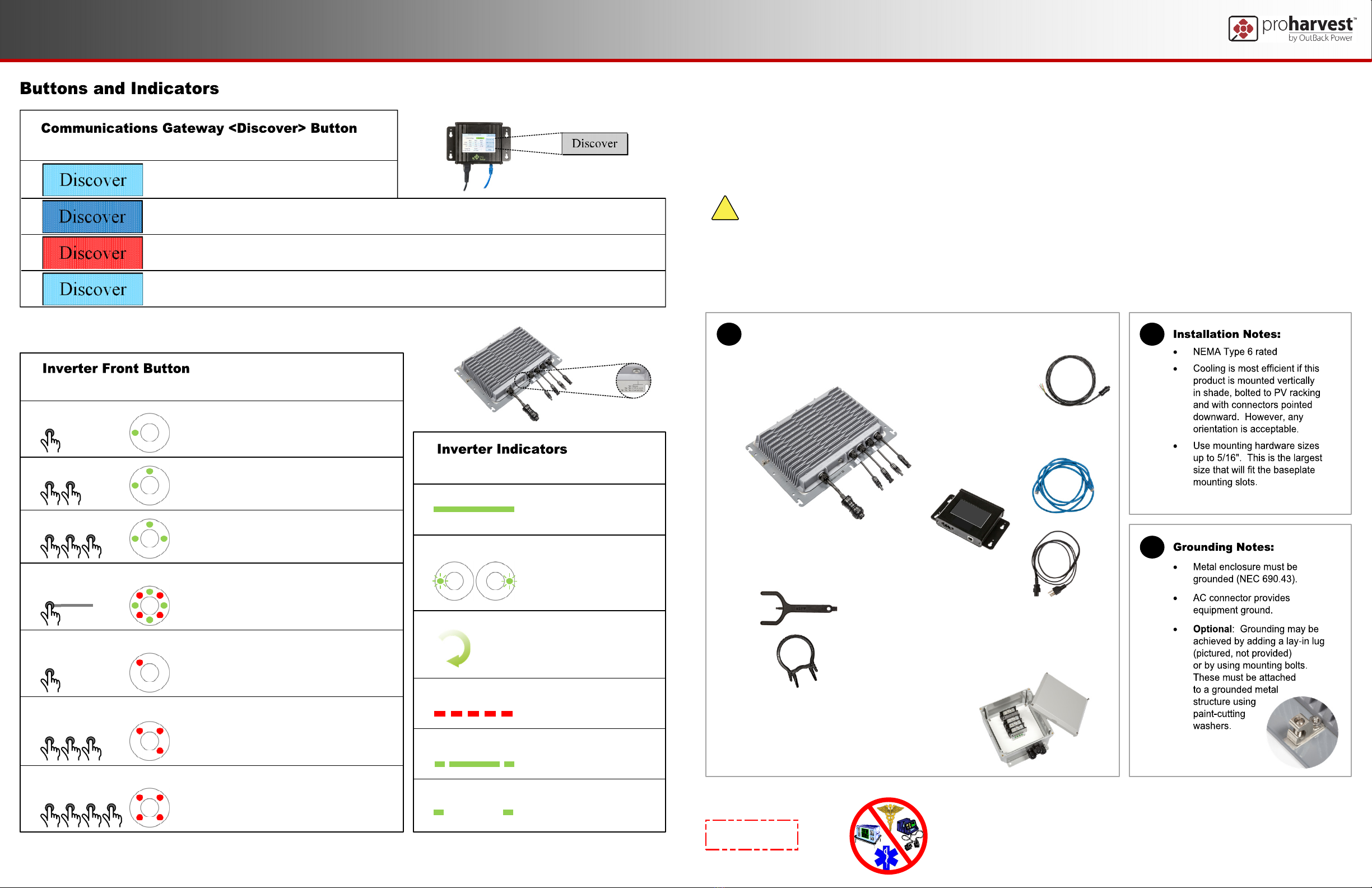
Indicator State
Solid
Left-right flash
Green chaser
Rapid flash
Mostly on
Mostly off
Meaning
Powered up
Not generating
No faults
Power-on self-test
Will take <1 minute
Powered up
Generating, no faults
Faulted; for example,
arc fault detected
“Off and Locked”;
unit is disabled
Sleeping
Not generating
900-0202-01-00 REV B
©2016 OutBack Power Technologies. All Rights Reserved.
IMPORTANT:
Not intended for use with
life support equipment.
Buttons and Indicators
ProHarvest 208V
Quick Start Guide
Date and Revision
January 2017, Revision B
This guide provides instructions for installation and setup of the product. It assumes knowledge of features, functions, and general operation.
This guide is a supplement for the purpose of expediting installation. For complete information, see the ProHarvest Installation and Safety Manual.
These instructions are for use by qualified personnel who meet all local and governmental code requirements for licensing and training
for the installation of 3-phase electrical power systems with AC and DC voltage up to 1000 volts.
!CAUTION: EQUIPMENT DAMAGE
This system is to be connected to 208 Vac 3-phase wye input ONLY (three phases, neutral, ground).
This product has no user-serviceable parts. Tampering with the product will void the warranty.
Applying incorrect polarity to DC string inputs will result in damage. This will void the warranty.
The Communications Gateway is for indoor use only.
All conductors (L1, L2, L3, neutral, ground) must be connected. Neutral must be bonded to earth ground. Failure
to do so can damage the inverter and void the warranty.
B
C
A
AC Cable (ordered separately)
CBL-208A-05 (5')
CBL-208A-15 (15')
CBL-208A-30 (30')
CBL-208A-50 (50')
Button State Meaning
Initial state.
Once pressed, a dark blue color indicates the Gateway is in the process of discovering inverters. It will return
to the initial state with an empty serial number list if no inverters are found.
A dark red color indicates an error was found. Examples: “signal strength is too low”; “too much background
noise on circuit”. The red color only clears when the user re-tries and the fault condition no longer applies.
Once discovery has successfully occurred, this button returns to the initial state.
Button Push
1 press
2 presses
3 presses
Long press
(> 2 secs)
1 press
(after long press)
3 presses
(after long press)
4 presses
(after long press)
Result
Make inverter beep; i.e. “Are you alive?”
“Off & Locked”. Unit is disabled.
Unit will not begin the 5-minute self-start.
Start generating immediately
If locked, unlock and generate immediately
If system is faulted, unit will unlock but
will not generate
“Alternate functions” mode:
Ready to accept further button pushes.
This times out after 10 seconds.
Clear latched faults; for example, after
residual-current device (RCD) test or
arc-fault test has initiated a fault condition.
RCD-test activation. Successful activation
of RCD test should cause a fault condition
(rapid red flashing) until cleared.
Arc-fault test activation. Successful activation
of arc-fault detection should cause a fault
condition (rapid red flashing) until cleared.
Button and
LED Indicator
Includes AC Connector Tool,
DC Connector Tool
TOOL-KIT-1
(ordered separately)
ProHarvest 208V Inverter
PRO208-5k75
PRO208-5k75-AUX
Communications Gateway
(ordered separately)
PROGW-A-120
Includes SD card, Ethernet cable,
120 Vac cable
AC Splice (optional component)
PROSPL-60

D
900-0202-01-00 REV B
©2016 OutBack Power Technologies. All Rights Reserved.
Installation
E F
Neutral
L1, L2, L3
Ground
Grid: Three-phase 208 Vac wye only
(neutral, ground, and three phases)
OCPD
Dedicated
branch circuit 60A max
overcurrent protective
device (OCPD)
Additional dedicated
branch circuits
15A OCPD
Neutral, ground,
and one phase
OCPD
Gateway
Neutral, ground,
and three phases Equipment ground
supplied through
AC connector
Connector
is means of
DC disconnect
(see H)
~
~
=
=
ProHarvest 208V
ProHarvest 208V
Equipment
ground
PV String 1
PV String 2
Connector is
means of
AC disconnect
(see D)
OCPD ProHarvest 208V
AC Splice
box
Inverter AC cable
(5-foot to 50-foot
lengths available)
5
I
H
!CAUTION: EQUIPMENT DAMAGE
Do not reverse the DC “+” and “–“ input polarities. This will damage the inverter and void the warranty.
1
G
1
2
3
4
6
5
7
2
89
10
~
=
Other Outback Inverter manuals


Popular Inverter manuals by other brands

EINHELL
EINHELL BT-PG 5000 DD Original operating instructions

tams elektronik
tams elektronik FI-1 manual

Toshiba
Toshiba TOSVERT VF-P7 instruction manual

Tektronix
Tektronix AFG3011C instructions

Chint Power
Chint Power CPS Series Installation and operation manual

Xantrex
Xantrex FREEDOM HF 1000 installation guide

ABB
ABB UNO-DM-2.0-TL-PLUS-Q product manual

Heckert Solar
Heckert Solar PV-Modules NeMo 4.2 80 M Installation and operating manual

Siemens
Siemens COMBIMASTER 411 Getting started guide

SMA
SMA SBS3.7-10 operating manual

Master Battery
Master Battery MasterPower Beta Series Installation and operation manual

JFY tech
JFY tech JSI-1100TL Installation and operator's manual


