RoseWater Energy Hub SB20 User manual

RoseWater Hub SB20
Installation Manual
043-012-C0-001, Rev. C
Effective Date: February 2020

Safety Notes
RoseWater Energy considers customer safety and satisfaction its most important priority. To reduce
the risk of injury or death and to ensure continual safe operation of this product, certain hazards are
identied by the icons below. RoseWater Energy adheres to ANSI Z535 and encourages special
attention and care to information presented in the following manner:
The following sections contain important safety information that must be followed during the installation and maintenance
of the equipment and batteries. Read all of the instructions before installing or operating the equipment, and save this
manual for future reference.
There may be multiple warnings associated with the call out. Example:
ATTENTION provides specic regulatory/code requirements that may affect the placement of equipment and /or
installation procedures.
ATTENTION:
NOTICE provides additional information to help complete a specic task or procedure.
NOTICE:
ELECTRICAL HAZARD WARNING provides electrical safety information to PREVENT INJURY OR DEATH
to the technician or user.
WARNING! ELECTRICAL HAZARD
FUMES HAZARD WARNING provides fumes safety information to PREVENT INJURY OR DEATH to the
technician or user.
WARNING! FUMES HAZARD
FIRE HAZARD WARNING provides ammability safety information to PREVENT INJURY OR DEATH to the
technician or user.
WARNING! FIRE HAZARD
This WARNING provides safety information for both Electrical AND Fire Hazards
WARNING! ELECTRICAL & FIRE HAZARD
CAUTION provides safety information intended to PREVENT DAMAGE to material or equipment.
CAUTION!
GENERAL HAZARD WARNING provides safety information to PREVENT INJURY OR DEATH to the
technician or user.
WARNING! GENERAL HAZARD

3043-012-C0-001, Rev. C (02/2020)
RoseWater Hub SB20
Installation Manual
043-012-C0-001, Rev. C
Effective Date: February 2020
© 2020 by RoseWater Energy Group
Disclaimer
Images contained in this manual are for illustrative purposes only. These images may not match your installation.
Operator is cautioned to review the instructions, drawings, and illustrations contained in this manual
before proceeding. If there are questions regarding the safe operation of this powering system, please
contact RoseWater Energy or your nearest RoseWater Energy representative.
RoseWater Energy shall not be held liable for any damage or injury involving its enclosures, power
supplies, generators, batteries or other hardware if used or operated in an unapproved manner or
subject to any condition not consistent with its intended purpose, or if it is improperly installed or
maintained.
Contact Information
Complete technical support in USA
(7AM to 5PM, Pacic Time or 24/7 emergency support):
Website:
1 800 863 3364
www.rosewaterenergy.com

4043-012-C0-001, Rev. C (02/2020)
Table of Contents
1.0 Introduction ..................................................................................................................................... 8
1.1 Theory of Operation............................................................................................................................... 8
1.2 RoseWater Hub SB20 Components ...................................................................................................... 9
2.0 System Pre-Installation................................................................................................................. 10
2.1 Site Selection....................................................................................................................................... 10
2.2 Floor Plan Layout................................................................................................................................. 10
2.3 Transporting and Unpacking the Cabinets........................................................................................... 10
2.4 Recommended Installation Layout ...................................................................................................... 11
2.5 Recommended Electrical Wiring/Ratings ............................................................................................ 14
3.0 System Installation........................................................................................................................ 15
3.1 Single Cabinet Mounting...................................................................................................................... 15
3.2 System Interconnection ....................................................................................................................... 16
3.3 Input / Output Cabling Access ............................................................................................................. 16
3.3.1 Wiring Gauge................................................................................................................................. 16
3.3.2 Grounding ...................................................................................................................................... 16
3.4 AC Connection Points.......................................................................................................................... 18
3.5 Communication Cables and Terminal Block Wiring ............................................................................. 19
3.5.1 SB20 Relay Binary Signals............................................................................................................ 20
3.6 Extended Battery Package Installation ................................................................................................ 23
3.7 SB20 to EBP Cabinet 1 Wire Connections .......................................................................................... 25
3.7.1 DC Connection Points, Wire Duct and Interconnect Cable Installation ......................................... 25
3.7.2 DC Battery Cabling ........................................................................................................................ 25
3.7.3 EBP Cabinet 1 to EBP Cabinet 2 Connections.............................................................................. 26
3.7.4 Auxiliary DC Input .......................................................................................................................... 26
3.7.5 SolarBox 10 Layout and Mounting Detail ...................................................................................... 27
3.7.6 SB20 Auxiliary DC Input Connections for Solarbox 10 .................................................................. 28
3.7.7 Solarbox 10 Wiring Connections.................................................................................................... 32
3.8 Battery Connections ............................................................................................................................ 34
4.0 System Components .................................................................................................................... 37
4.1 Overview of the LCD Interface............................................................................................................. 37
4.2 Recitier Features................................................................................................................................ 38
4.2.1 Front Panel LEDs........................................................................................................................... 38
4.3 Inverter Module Indicators ................................................................................................................... 39
4.3.1 Status LEDs................................................................................................................................... 39
4.4 T2S Inverter Control Card.................................................................................................................... 40
5.0 System Start-Up and Conguration .............................................................................................. 41
5.1 Commissioning the System for the First Time ..................................................................................... 41
5.1.1 Tools Required............................................................................................................................... 41
5.1.2 Prior to Start-Up............................................................................................................................. 42
5.2 Starting the System ............................................................................................................................. 43
5.3 Commissioning the Inverter System .................................................................................................... 45
5.3.1 Setting System Options ................................................................................................................. 45
5.3.2 Commission Seed Inverters........................................................................................................... 46
5.3.3 Adding Inverters............................................................................................................................. 46
5.4 System Functional Test........................................................................................................................ 46
5.5 Synchronizing the Maintenance Bypass Switch .................................................................................. 47
5.5.1 Implement the following steps before switching from Inverter mode to Bypass mode. ................. 47
5.5.2 Implement the following steps before switching from Bypass mode to Inverter Mode. ................. 47

5043-012-C0-001, Rev. C (02/2020)
5.6 Start-up Completion............................................................................................................................. 47
5.7 Solarbox 10 Power Up......................................................................................................................... 48
5.8 Solarbox 10 Protective Features ......................................................................................................... 49
6.0 System Shutdown......................................................................................................................... 50
6.1 Main Control Off Push Button .............................................................................................................. 50
6.2 External Emergency Shutdown ........................................................................................................... 50
6.3 Cordex Controller................................................................................................................................. 51
6.4 Re-initiating the System....................................................................................................................... 51
7.0 Site-Specic Cordex Settings ....................................................................................................... 52
7.1 Changing Cordex CXC-HP Time and Date.......................................................................................... 52
7.2 Create Unique Name Specic to SB20 System for Email Notication.................................................. 53
7.3 SB-EBP Battery Capacity Conguration ............................................................................................... 54
7.4 Solarbox 10 Cordex Conguration Changes ....................................................................................... 55
7.5 Email Notications from the Cordex CXC-HP...................................................................................... 58
7.6 Change Cordex Login Passwords ....................................................................................................... 59
7.7 SB20 Beagle Bone & Cordex Reset to Re-establish SSH Tunnel....................................................... 60
7.8 Save System Backup on Flash Drive .................................................................................................. 61
8.0 Technical Specications................................................................................................................ 62
8.1 SB20 Specications....................................................................................................................... 62
8.2 Solarbox 10 Specications............................................................................................................. 66
9.0 Maintenance ................................................................................................................................. 67
9.1 RoseWater SB20 Spare Parts ............................................................................................................. 67
9.2 RoseWater Annual Maintenance and Troubleshooting Guide ............................................................. 67
9.2.1 Checkoff Sheet for Removing Failed Inverter Modules ................................................................. 69
9.2.2 Rectier Module Cleaning.............................................................................................................. 70
9.2.3 CXC-HP Controller......................................................................................................................... 70
9.3 Surge Suppression Replacement ........................................................................................................ 71
9.3.1 Citel TVSS Inspection and Replacement....................................................................................... 71
9.3.2 Service Entrance Grade Strikesorb TVSS Replacement............................................................... 72
9.4 Bypass Fuse Replacement.................................................................................................................. 73
9.5 Battery Maintenance............................................................................................................................ 74
Table of Contents, continued

6043-012-C0-001, Rev. C (02/2020)
Figures
Fig. 1-1, System Power Diagram - SB20............................................................................................... 8
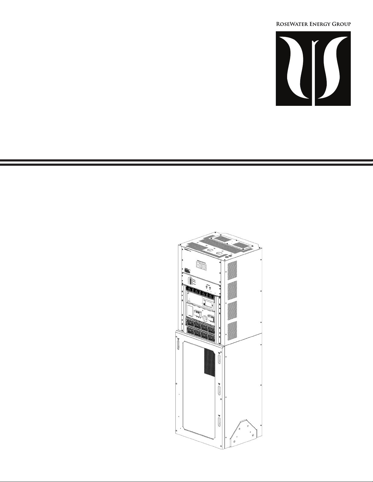
Fig. 1-2, RoseWater Hub SB20 ............................................................................................................. 9
Fig. 2-1, RoseWater SB20 System Clearance .....................................................................................11
Fig. 2-2, RoseWater SB20 and SB-EBP System Clearance ............................................................... 12
Fig. 2-3, System Dimensions............................................................................................................... 13
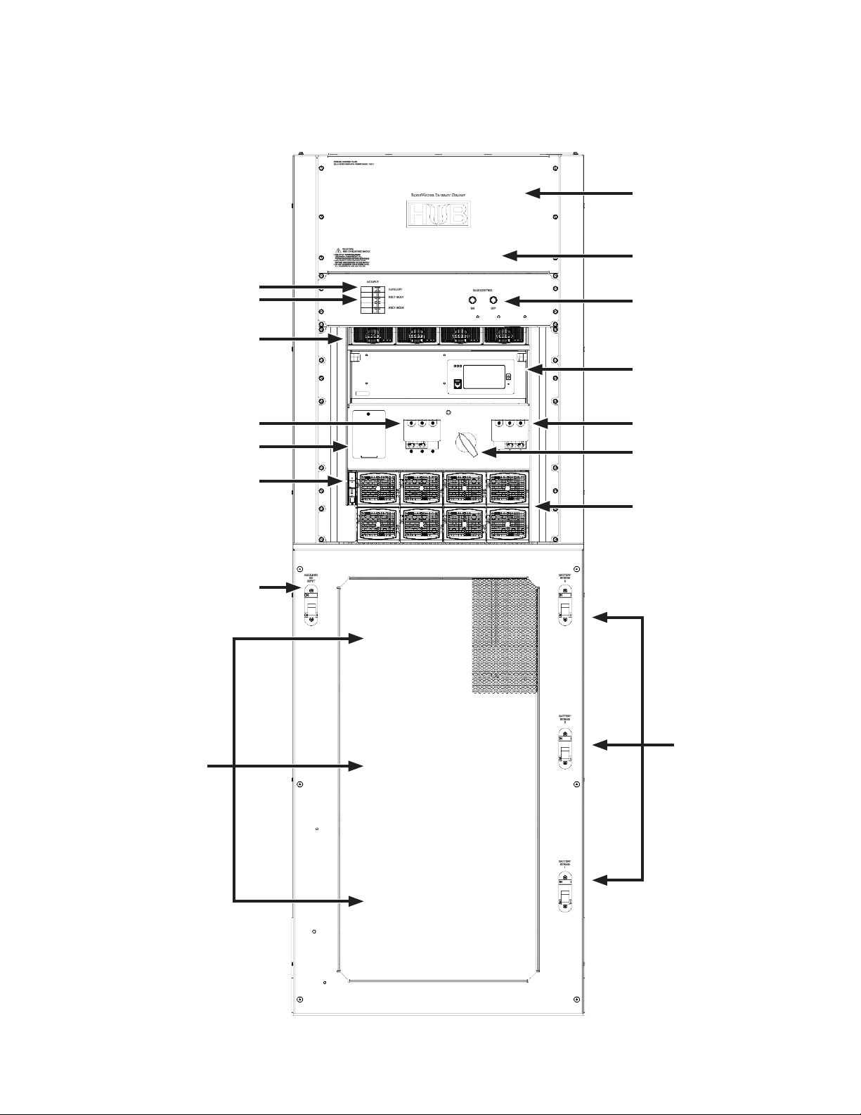
Fig. 3-1, Single SB20 Enclosure.......................................................................................................... 15
Fig. 3-2, SB20 Wiring Access Panel and Knockouts........................................................................... 17
Fig. 3-3, SB20 AC Input/Output Lugs .................................................................................................. 18
Fig. 3-4, Internet and Terminal Block Connection................................................................................ 19
Fig. 3-5, Cordex Flip Down Panel........................................................................................................ 21
Fig. 3-6, Removing Rear Cover........................................................................................................... 22
Fig. 3-7, Routing Binary Sense Wires ................................................................................................. 22
Fig. 3-8, Wire Duct Installation ............................................................................................................ 23
Fig. 3-9, System Congured with Second EBP................................................................................... 24
Fig. 3-10, Battery Cable Connection Points, SB20 Cabinet ................................................................ 25
Fig. 3-11, Battery Cable Connection Points, EBP Cabinet 1 ............................................................... 26
Fig. 3-12, Solarbox 10 Layout and Mounting Details .......................................................................... 27
Fig. 3-13, Auxiliary DC Input Cable Connection Points, SB20 Cabinet............................................... 28
Fig. 3-14, 45° Bus Bar Adapters ......................................................................................................... 29
Fig. 3-15, Removing Access Cover .................................................................................................... 29
Fig. 3-16, SB20 Wire 101 ................................................................................................................... 29
Fig. 3-17, Ground Fault Warning Label Placement ............................................................................. 30
Fig. 3-18, Battery Sense Fuse Holder Placement .............................................................................. 30
Fig. 3-19, Jumper Wire 194 Location .................................................................................................. 31
Fig. 3-20, Solarbox 10 RTS Placement............................................................................................... 31
Fig. 3-21, Solarbox 10 Wiring Connections......................................................................................... 32
Fig. 3-22, Solarbox 10 PV Connections .............................................................................................. 32
Fig. 3-23, Rapid Shut Down (RSD) and Remote Temperature Sensor (RTS) Connections................ 33
Fig. 3-24, Solarbox 10 Internet 2 Connection...................................................................................... 33
Fig. 3-25, Representative Connection of Intercell Bars and Cordex Temperature Sensors ................ 34
Fig. 3-26, Front Terminal Battery Hardware Stack Up......................................................................... 35
Fig. 3-27, Battery Arrangement (200PLR Batteries with Adapters Shown) ......................................... 36
Fig. 4-1, CXC-HP Controller Dashboard ............................................................................................. 37
Fig. 4-2, Rectier Front Panel LEDs.................................................................................................... 38
Fig. 4-3, Inverter Module Status, Power LEDs .................................................................................... 39
Fig. 4-4, Output power indicator LEDs ................................................................................................ 39
Fig. 4-5, T2S Front Panel .................................................................................................................... 40
Fig. 5-1, Inverter Module Positions...................................................................................................... 44
Fig. 5-2, Commission Inverter System Wizard .................................................................................... 45
Fig. 5-3, GFDI Fuse Holder ................................................................................................................. 49
Fig. 7-1, Time and Date....................................................................................................................... 52
Fig. 7-2, Controller Description............................................................................................................ 53
Fig. 7-3, Battery Capacity Conguration.............................................................................................. 54

7043-012-C0-001, Rev. C (02/2020)
Tables
Table 1-1, RoseWater System Models - SB20 ...................................................................................... 8
Table 2-1, RoseWater System AC Input / Output ................................................................................ 14
Table 3-1, SB20 Relay Binary Signals Key.......................................................................................... 20
Table 4-1, Inverter Alarm Indicators and Troubleshooting ................................................................... 39
Table 8-1, Electrical Specications ...................................................................................................... 62
Table 8-1, Electrical Specications, continued .................................................................................... 63
Table 8-2, Monitoring and Controls Specications .............................................................................. 64
Table 8-3, Mechanical Specications .................................................................................................. 65
Table 8-4, Environmental Specications.............................................................................................. 65
Table 3-2, Solarbox 10 Specications ................................................................................................. 66
Table 9-1, SB20 Spare Parts List ........................................................................................................ 67
Table 9-2, Reference Manuals............................................................................................................. 69
Table 9-3, Battery Maintenance Log.................................................................................................... 75
Fig. 7-4, Custom Data Page................................................................................................................ 55
Fig. 7-5, Action Button Location........................................................................................................... 55
Fig. 7-6, Turning On PV Consumption Algorithm................................................................................. 55
Fig. 7-7, Congure System Page ........................................................................................................ 56
Fig. 7-8, Elevated Absorption Voltage ................................................................................................. 56
Fig. 7-9, Power Flow Diagram............................................................................................................. 57
Fig. 7-10, Set SMTP Server Password................................................................................................ 58
Fig. 7-11, Email Destination................................................................................................................. 58
Fig. 7-12, Reset Controller .................................................................................................................. 59
Fig. 7-13, Change Cordex Login Password......................................................................................... 59
Fig. 7-14, Flip Down Panel Location.................................................................................................... 60
Fig. 7-15, Beagle Bone Power Input Connector Location ................................................................... 60
Fig. 7-16, Flash Drive Location............................................................................................................ 61
Fig. 9-1, TVSS Surge Supressors Location and Detail ....................................................................... 71
Fig. 9-2, TVSS Surge Supressors and Bracket................................................................................... 72
Fig. 9-3, Installing the Bracket............................................................................................................. 72
Fig. 9-4, Bypass Fuse Location........................................................................................................... 73
Fig. 9-5, Detail, Bypass Fuse Location................................................................................................ 73
Figures, continued

8043-012-C0-001, Rev. C (02/2020)
1.0 Introduction
1.1 Theory of Operation
The RoseWater Hub SB20 system is a Double Conversion Energy Storage System (ESS) that provides conditioned
back up power to critical loads. It is intended for critical powering in large residential and small commercial applications.
Placement of the system is intended to be in a temperature controlled, clean environment (e.g. A/V room, utility room, or
garage).
The SB20 is a single bay system that houses ESS inverters, supervisory components, switch mode rectiers for
battery charging and three battery strings. Two shelves of inverter modules are used to supply a critical load panel with
conditioned 120/240V AC power up to 20kVA derived from the utility source when it is available and inverted from the
DC bus sources when utility line power is not available. One shelf of the system supplies L1 phase and the second shelf
supplies L2 power in a split phase arrangement. An individual inverter shelf accommodates up to (4) removable inverter
modules to match power or redundancy needs of the system. The system also includes a mechanical wraparound switch
providing AC bypass from the utility source to the load when needed for maintenance of the inverter. The bypass switch is
make before break providing seamless output power when operated. Two rectier modules are used to provide 3.84KW of
battery recharge power. There are three 48VDC battery strings for a total of 28.8KWh capacity at the 100hr rate.
The system is designed to accept additional Extended Battery Package (SB-EBP) for increased battery capacity. It also
has an auxiliary 48VDC input that can accept up to 200A from a charging source such as PV array, wind turbine or other
energy source.
RoseWater System – SB20
Model Number SB20-28-240-NC
Factory Congured SB20 20 kVA, 120/240V
2.5 kVA Inverter Modules 8
Inverter Maintenance Bypass Switch (MBS) Internal “Make Before Break”
Rectier Battery Charging Modules (2), 80A at 48VDC total
Batteries 28.8 kWh Battery, (2-3) 48V Battery Strings
Optional Features (Not Provided)
AC Generator
(Generator Transfer Switch - “Break Before Make”) 120/240 VAC Single Phase
Extended Battery Package (SB-EBP-28-NC) 28.8 kWh Battery, (3) 48V Battery Strings
(MDP)
Main Distribution Panel
Non-Critical Circuits
120/240 VAC
Single Phase
ESS, 20KVA, 120/240VAC, 28KWH, SB20
Critical Load Panel,
100A, 120/240V
Utility 120/240V
Single Phase, 60Hz Non-Critical Load Circuit
Optional Transfer Switch
Break Before Make
125 Amp
120/240VAC, 4 wire
Phase (L1, L2, N, G)
120/240VAC, 4 wire
Phase (L1, L2, N, G)
120/240VAC 4 wire
(L1, L2, N, G)
Critical Circuits
(Typical)
Optional AC
Generator 120/240V,
Single Phase, 60Hz
Optional Extended
Battery Package
(SB-EBP)
Optional Auxiliary
48VDC Input from
PV Array or other
DC source
*Note1: Circuit must be capable of
delivering no more than 5KA short-circuit
current RMS symmetrical amperes. Fused
disconnect or similar may be required.
Note2: Any disconnect must be installed
in accordance with NEC code 706.7
Disconnecting Means. Disconnect must
be within 5ft of ESS.
ESS
5ft Max.
Current
Limiting*
Disconnect
125 Amp
Single Phase
120/240V
Table 1-1, RoseWater System Models - SB20
Fig. 1-1, System Power Diagram - SB20

1.0 Introduction, continued
9043-012-C0-001, Rev. C (02/2020)
1.2 RoseWater Hub SB20 Components
Inverter AC Output Circuit Breaker
(8-12) 200AH VRLA
Batteries
(3) 250ADC Battery
Breakers - One Per
String
(8) Inverter Modules and
Shelves
Fig. 1-2, RoseWater Hub SB20
Cordex (CXC) HP Controller
with Ethernet/SNMP
Flip Down Panel
(2) Rectier Battery
Charging Modules
Master On/Off Push Buttons
AC Input Circuit Breakers
Auxiliary (Blue LED Lights)
Rectier Module Circuit Breakers
Inverter AC Input Circuit Breaker
Inverter Maintenance Bypass
Switch (MBS)
Auxiliary DC Input
Circuit Breaker 250A
T2S Inverter Control Card
TVSS Module Cover
AC Input/Output Access Cover
Strikesorb Surge Arrestor Access

10 043-012-C0-001, Rev. C (02/2020)
2.0 System Pre-Installation
2.1 Site Selection
The RoseWater Hub SB20 is designed to be installed in a controlled environment (maximum ambient temperature of
104°F), sheltered from rain, excessive dust and other contaminants. See Table 8-4.
The batteries used in the RoseWater Hub SB20 are valve regulated lead acid and may off-gas hydrogen. The area the
system is installed in must be well ventilated to prevent the build up of potentially explosive combinations of hydrogen and
oxygen. Ventilation may either be passive or active with active systems requiring redundancy in case of fan failure. See
Table 8-4 for Environmental Specications.
Consider both the oor loading and the physical space required for the RoseWater SB20 power system and the batteries.
See Section 2.4 for clearance and Table 8-3 for weight requirements.
2.2 Floor Plan Layout
Sufcient free space must be provided at the front, rear, and sides of the power system to meet the cooling requirements
of the power system and to allow easy access to components.
Consider the following before selecting a location for the RoseWater power system:
• Structure of the building able to support the additional weight of the system.
• Enough space to meet the requirements for access to the system. See Section 2.4.
• Adequate cooling to compensate for additional heat per Section 8.0 Technical Specications, Table 8-4.
• Perform the following actions to ensure proper performance of the system:
• Ensure that the loads that are powered by the system do not exceed system surge or capacity ratings.
• Calculate and record the backup energy/power required for the batteries/DC power source to assure desired
backup time.
• Determine the pre-installation preparations that must take place:
• Determine the wiring and conduit routing that must take place for the AC input disconnects.
• Determine the wiring and conduit routing that must take place for the AC output critical load panel.
• Determine the wiring and conduit routing that must take place for the Auxiliary DC or Solar Array input (if
applicable).
• Determine the wiring and routing for the RoseWater HUB’s network connection to the internet.
2.3 Transporting and Unpacking the Cabinets
A third-party, specializing in the transportation of large electrical systems, handles the shipping, unpacking, and placing
of the cabinets. The cabinets are individually crated and shipped on pallets to prevent damage. The cabinets are then
interconnected on-site. The Inverter Modules, Rectier Modules and Batteries are to be installed after the cabinet has
been placed.

2.0 System Pre-Installation, continued
11043-012-C0-001, Rev. C (02/2020)
2.4 Recommended Installation Layout
2.4.1 Single Bay Layout
Minimum required clearances around the cabinet (the oor must be at and level):
• Rear: 12in
• Sides: 12in
• Top: 16in
• Front: 36in for ventilation, door clearance, and service access
28 1
8
"
26 1
4
"
22 5
8
"
10 5
8
"
7 7
8
"
2 3
4
"
12" MIN
FROM WALL
12" MIN
FROM WALL
12" MIN
FROM WALL
36" MIN FOR
SERVICE ACCESS
SB20
ANCHOR
BOLT
(QTY. 4)
Fig. 2-1, RoseWater SB20 System Clearance

2.0 System Pre-Installation, continued
12 043-012-C0-001, Rev. C (02/2020)
2.4.2 Double Bay Layout
Minimum required clearances around the cabinet (the oor must be at and level):
• Rear: 12in
• Sides: 12in
• Between Cabinets: 4in
• Top (excluding wiring duct): 16in
• Front: 36in for ventilation, door clearance, and service access
Fig. 2-2, RoseWater SB20 and SB-EBP System Clearance
12" MIN
FROM WALL
36" MIN FOR
SERVICE ACCESS
28 1
8
"
26 1
4
"
12" MIN
FROM WALL
4"
28 1
8
"
22 5
8
"
10 5
8
"
7 7
8
"
2 3
4
"
9 3
8
"
22 5
8
"
12" MIN
FROM WALL
SB20 UPS
SB-EBP
ANCHOR
BOLT
(QTY. 8)

2.0 System Pre-Installation, continued
13043-012-C0-001, Rev. C (02/2020)
Fig. 2-3, System Dimensions
28.1"
84.5"
4"
88"
(with cabling duct)
100"
(with cabling duct and
proper clearance)
28.1"
(Wire duct with SB-EBP - optional)
(SB-EBP - optional)

2.0 System Pre-Installation, continued
14 043-012-C0-001, Rev. C (02/2020)
2.5 Recommended Electrical Wiring/Ratings
RoseWater System SB20, Split-Phase, 2-Pole Systems, Single AC Feed
SB20 AC Input
Inverter Modules 8
Module Redundancy per Phase N+0
AC Input Voltage 120/240V or 120/208V
Full Load AC Input Current per Phase
(Includes 20A Charger Current per Phase) 100A
AC Input Wiring 3 w + G
AC Input Circuit Breaker Poles 2-pole
Recommended Minimum AC Input Breaker 125A
Recommended Minimum AC Input Wire Size 90°C Copper 1AWG
SB20 AC Output
Total Maximum AC Output 20 kVA, 16 kW
AC Output Voltage 120/240V or 120/208V
AC Output Wiring 3 w + G
AC Output Circuit Breaker Poles 2-pole
AC Output Current per Phase 80A
Installed Inverter Output Circuit Breaker 100A
Recommended Minimum AC Output Wire Size 90°C Copper 1AWG
• AC Input and AC Output connection terminal lugs are rated for either aluminum or copper wire, 2/0 to 14AWG.
Fasten clamping screws to 120 in-lb. (14 Nm)
• Calculations for the Inverter AC Input and AC Output connections are based on full load and charging current.
Temperature correction factors were applied when necessary. The AC Output wire size must be equal to or
greater than the AC Input wire size.
• The actual supply circuit breaker must be sized appropriately for the supply wire and actual load used. Consult
applicable local and national electrical codes. The AC source must be limited to 5kA short circuit current.
• Any disconnect must be installed in accordance with NEC code 706.7 Disconnecting Means. Disconnect must
be within 5 ft of ESS.
• In addition to these considerations, RoseWater recommends that the installer review the RoseWater HUB SB20
System Wiring Diagram prior to installation (p/n 043-012-08).
NOTICE:
The recommendations below are for reference only. A registered professional engineer must review and approve or
modify these recommendations in compliance with applicable national and local electrical and building codes.
NOTICE:
Table 2-1, RoseWater System AC Input / Output

15043-012-C0-001, Rev. C (02/2020)
3.0 System Installation
3.1 Single Cabinet Mounting
The cabinet must be xed in place to the oor by following the steps outlined below.
Prior to installation, verify that there is sufcient space between and around the cabinet (see Section 2.4, Recommended
Installation Layout).
1. Verify that the mounting surface is level.
2. Use a rebar locator to plan for the anchor positions.
3. Use the dimensions provided for the cabinet (See Section 2, “System Pre-Installation”) to mark and drill the
anchor hole positions with an 18 mm rotary hammer drill bit.
4. Install the Hilti HSL-3 M12/25 anchoring hardware to set the insert for each anchor, then remove the anchor bolt.
5. Move the cabinet to the exact, nal position over the anchoring holes.
6. Verify that the cabinet is level (or plumb). Shim as necessary.
7. Install the Hilti HSL-3 M12/25 anchor bolts, or equivalent, with the included seismic washers.
8. Use a torque wrench with a 3/4” socket to torque all of the anchor bolts to 59 ft-lbs.
Fig. 3-1, Single SB20 Enclosure

3.0 System Installation, continued
16 043-012-C0-001, Rev. C (02/2020)
3.2 System Interconnection
The RoseWater Hub SB20 system is pre-congured from the factory for a single AC feed per phase for rectiers, inverters
and the maintenance bypass switch.
The installer is responsible for connecting the following:
• Utility input (240V Split Phase, or 2 legs of 208V) to the system (120V line to neutral).
• Battery strings (Do not fully install the batteries until instructed; set them in place on the battery shelves).
• System to the load.
• Chassis and battery return to the reference ground.
• 1 Ethernet (CAT5 or better) connection is required for RoseWater Hub SB20 internet connectivity.
Carefully review the following installation notes before proceeding with the installation.
Installation Notes:
• Inspect the system for loose wires and connections due to transit.
• All wiring must be in accordance with applicable electrical codes.
• Inverter main input must always include a neutral connection.
• Power and control cables must be in separate conduits.
Refer to the RoseWater Energy Hub System Wiring Diagram (p/n 043-012-08) for battery and power connections.
3.3 Input / Output Cabling Access
AC input/output connections are accessed from the front of the system rack using a 3/8" hex driver. The panel marked
“Wiring Access Panel” at the top of the SB20 must be removed to access the AC connection points. A protective panel
partitions the AC and DC connection points in the SB20. The front panel at the top of the SB-EBP and the rear covers of
both cabinets must be removed to access the DC connection points.
To maintain the security of all Safety Extra-Low Voltage (SELV) Circuits in the RoseWater Energy HUB SB20,
connect to other equipment of the same circuit type: signaling/alarm circuits, emergency power off (EPO)
circuits, relay contacts, Ethernet or CANBUS.
WARNING! ELECTRICAL HAZARD
Ensure that all breakers are OFF prior to wiring the Rosewater system.
WARNING! ELECTRICAL HAZARD
3.3.1 Wiring Gauge
The input wire feed gauge should be determined by a certied electrician based on the length of run and load. Refer to
Table 2-1.
3.3.2 Grounding
Refer Figure 3-3, Top View of SB20 - AC and DC Connection Partitions, for connection points for the neutral connection
points as well as the AC frame ground.

3.0 System Installation, continued
17043-012-C0-001, Rev. C (02/2020)
Fig. 3-2, SB20 Wiring Access Panel and Knockouts
AC INPUT 2" KNOCKOUT AC OUTPUT 2" KNOCKOUT
REMOTE INTERFACE
CONTROL WIRES (OPTIONAL)
ETHERNET

3.0 System Installation, continued
18 043-012-C0-001, Rev. C (02/2020)
3.4 AC Connection Points
The following connections must only be installed by a certied electrician.
WARNING! GENERAL HAZARD
AC INPUT LUGS
L1 L2 N
AC OUTPUT LUGS
L1 L2
N
• Access to AC Input/Output connections is through the front of the cabinet.
• AC wires must be fed through the conduit knockouts on top of the cabinet.
• AC Input and AC Output connection terminal box lugs are rated for either Aluminum or Copper wire, 2/0 to
14AWG. Fasten clamping screw to 120 in-lbs (14 Nm).
Fig. 3-3, SB20 AC Input/Output Lugs
GROUND CONNECTIONS

3.0 System Installation, continued
19043-012-C0-001, Rev. C (02/2020)
Fig. 3-4, Internet and Terminal Block Connection
INTERNET CONNECTION
DC CONTROL TERMINAL BLOCK
SB20 Internet Connection
The SB20 is equipped with an RJ45 Ethernet connector for internet connectivity.
SB20 DC Control Terminal Blocks
The SB20 DC Control Terminal block is used to land remote interface control wires from outside the system.
EPO Terminal Blocks 3 and 4:
• Remove wire jumper if Remote Emergency Power Off (EPO) option is used. Open contact will cause shutdown.
EPO disconnects system power inputs and outputs upon a dry contact opening.
• Signal: 48VDC, 5W Nominal holding circuit must be broken to initiate EPO.
• Actuator Location: Remote (up to 50 ft from SB20)
PV RSD Terminal Blocks 7 and 9:
• PV Rapid Shut Down contacts can be used to initiate a Rapid shut down on PV system that is installed separately
from the SB20 but provides Auxiliary DC Input. PV RSD contact is closed when the SB20 is powered and opens
when SB20 is shut down. Dry contact is isolated from the rest of the system.
Gen Enable Relay contacts Terminal Blocks 10-12:
• Gen Enable Relay contacts can be used to start and stop a remote generator. Programmable contacts are
available for generator start on low DC bus. Form C dry contact NC, COM, NO. 60VDC, 1A maximum.
Gen Active Sens Digital input Terminal Blocks 13 and 14:
• Remove wire jumper if Gen Active Sens Digital input option is used. Open Contact will indicate that an automatic
transfer switch has been activated or that a remote generator is running.
• Signal: 48VDC, 0.2W circuit must be broken to initiate digital alarm.
• Actuator Location: Remote (up to 50 ft from SB20)
See system wire diagram 043-012-08 for more detail.
3.5 Communication Cables and Terminal Block Wiring

3.0 System Installation, continued
20 043-012-C0-001, Rev. C (02/2020)
3.5.1 SB20 Relay Binary Signals
The Rosewater SB20 is capable of sending binary signals to an external monitoring system to indicate the status of the
Energy Storage System. The Cordex Controller L-ADIO has four designated relays, K9 to K12 that are programmed to
respond to specic system conditions. See the SB20 Relay Signals Key below:
SB20 Relay Binary Signals Key
Cordex L-ADIO Relay States
K12 K11 K10 K9 Signal Names Signal Notes
0 0 0 0 Cordex is powered down
Could occur:
1. SB20 in Bypass Mode with Cordex off
2. SB20 disconnected for maintenance
3. Cordex Controller momentarily reset
0001 Cordex Runtime calculation is unavailable
Could occur:
1. During low level battery discharges when
there may be a short delay before Estimated
Battery Runtime is reported,
2. After LVD,
3. If a battery breaker is switched off, or
4. When other system conditions don't allow
Runtime to be calculated
0 0 10AC power off, more than 12 hours run time
0 0 1 1 AC power off, 10–12 hours run time
010 0 AC power off, 8–10 hours run time
0101 AC power off, less than 8 hours run time
0110AC power off, less than 7 hours run time
01 1 1 AC power off, less than 6 hours run time
1000AC power off, less than 5 hours run time
1001 AC power off, less than 4 hours run time
1010AC power off, less than 3 hours run time
101 1 AC power off, less than 2 hours run time
1 1 0 0 AC power off, less than 1.5 hours run time
1 1 01 AC power off, less than 1 hour run time
1110AC on, batteries 100% Normal operating mode, batteries fully charged
1 1 1 1 AC restored Utility power is available, but the batteries have
not yet been fully recharged
0 = de-energized; 1 = energized. K9 relay switches the least signicant bit, relay 12 switches the most signicant bit.
App Notes
Load Shedding
When loads are shed, the alarm state will change as runtime increases. This could result in cycling back and forth
between states if the load shedding algorithm is not carefully planned. It is recommended to not reconnect any loads once
they are shed until AC power has been restored.
Table 3-1, SB20 Relay Binary Signals Key
Table of contents
Popular Inverter manuals by other brands

Assurance Engineering
Assurance Engineering Assuramce Emergency Lighting Si-125 Installation & operation manual

SolaX Power
SolaX Power X1-Fit-3.7C user manual

Generac Power Systems
Generac Power Systems Guardian 04389-1 Installation and owner's manual

Johnson Controls
Johnson Controls VS3-005-4-UL1-0 quick start guide

DSPM
DSPM Defender Micro Elite Maintenance manual

Solax
Solax X1-1.1-S-N user manual