Outback OUT370665/PH300 User manual
0063
Signature Stainless Steel Flame Tower
®
Drawings are not to scale.
Specifications subject to change
without prior notice.
FOR YOUR SAFETY
If you smell gas:
1. Shut off gas to the appliance.
2. Extinguish any open flame.
3. If odor continues, immediately call your
gas supplier or your fire Department.
FOR YOUR SAFETY
1. Do not store or use gasoline or other flammable
vapors and liquids in the vicinity of this or any
other appliance.
2.An LP cylinder not connected for use shall not be
stored in the vicinity of this or any other appliance.
OUT370665/PH300
Assembly and Operating Instructions for Outback
2
WARNlNG SAFETY RULES
PLEASE READ THE FOLLOWING SAFETY RULES PRlOR TO OPERATION
OF THE HEATER.
WARNlNG
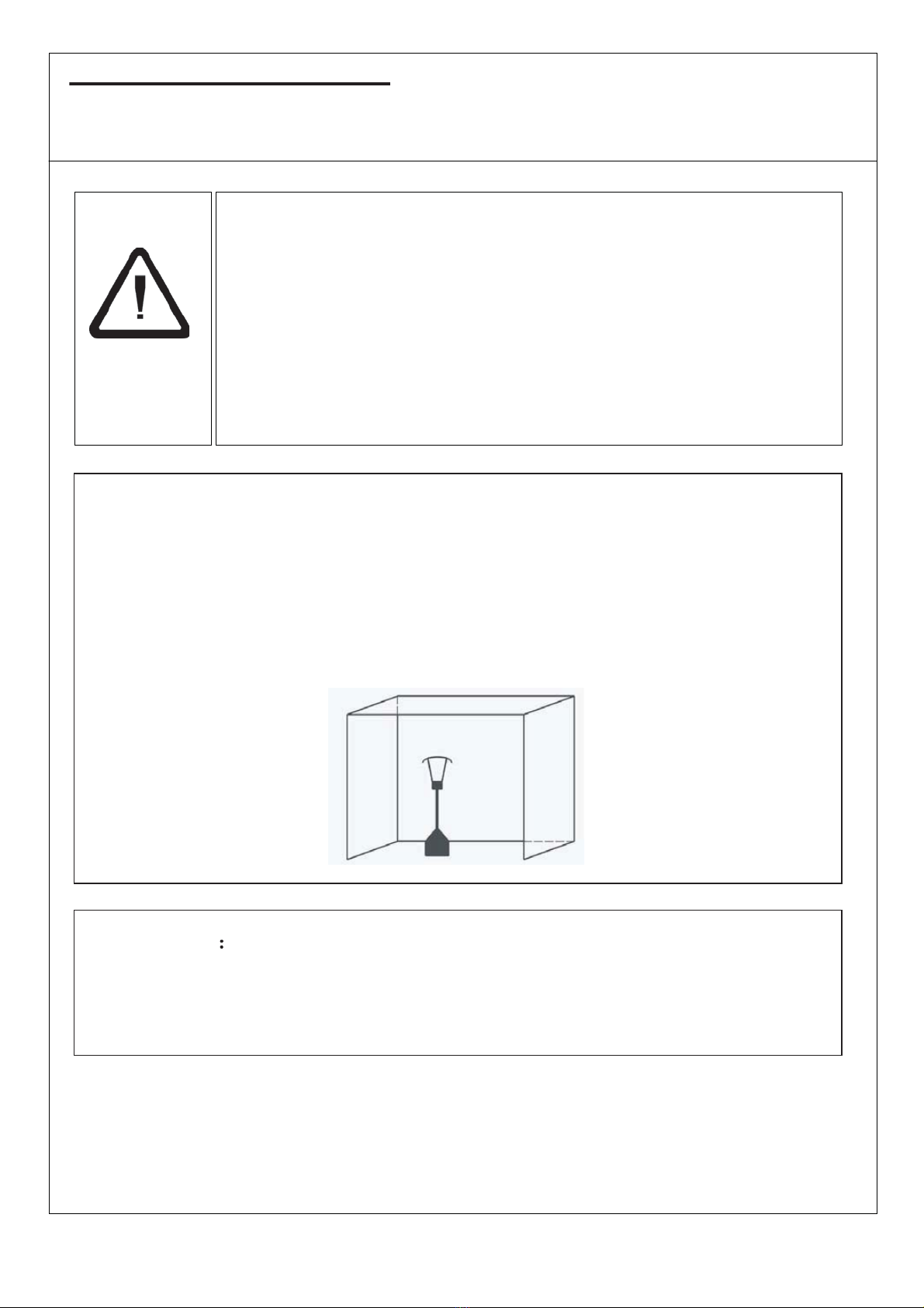
1) For use outdoors or in amply ventilated areas.
2) An amply ventilated area must have a minimum of 25 % of the
surface area open.
3) The surface area is the sum of the walls surface.
WARNING Improper installation, adjustment, alteration, service
or maintenance Can cause injury or property damage. Read the
installation, operating and maintenance instructions thoroughly
before installing or servicing this equipment.
WARNING
xThis appliance must be installed and the gas cylinder stored in accordance with the
regulations in force;
xDo not obstruct the ventilation holes of the cylinder housing;
xDo not move the appliance when in operation;
xShut off the valve at the gas cylinder or the regulator before moving the appliance;
xThe tubing or the flexible hose must be changed within the prescribed intervals;
xUse only the type of gas and the type of cylinder specified by the manufacturer;
The LP tank used with your patio heater must meet the following requirements:
Purchase LP tanks only with these required measurements:
(31.8cm) (diameter) x 58cm) (tall) with 15kg capacity maximum.
xIn case of violent wind particular attention must be taken against
tilting of the appliance;
3
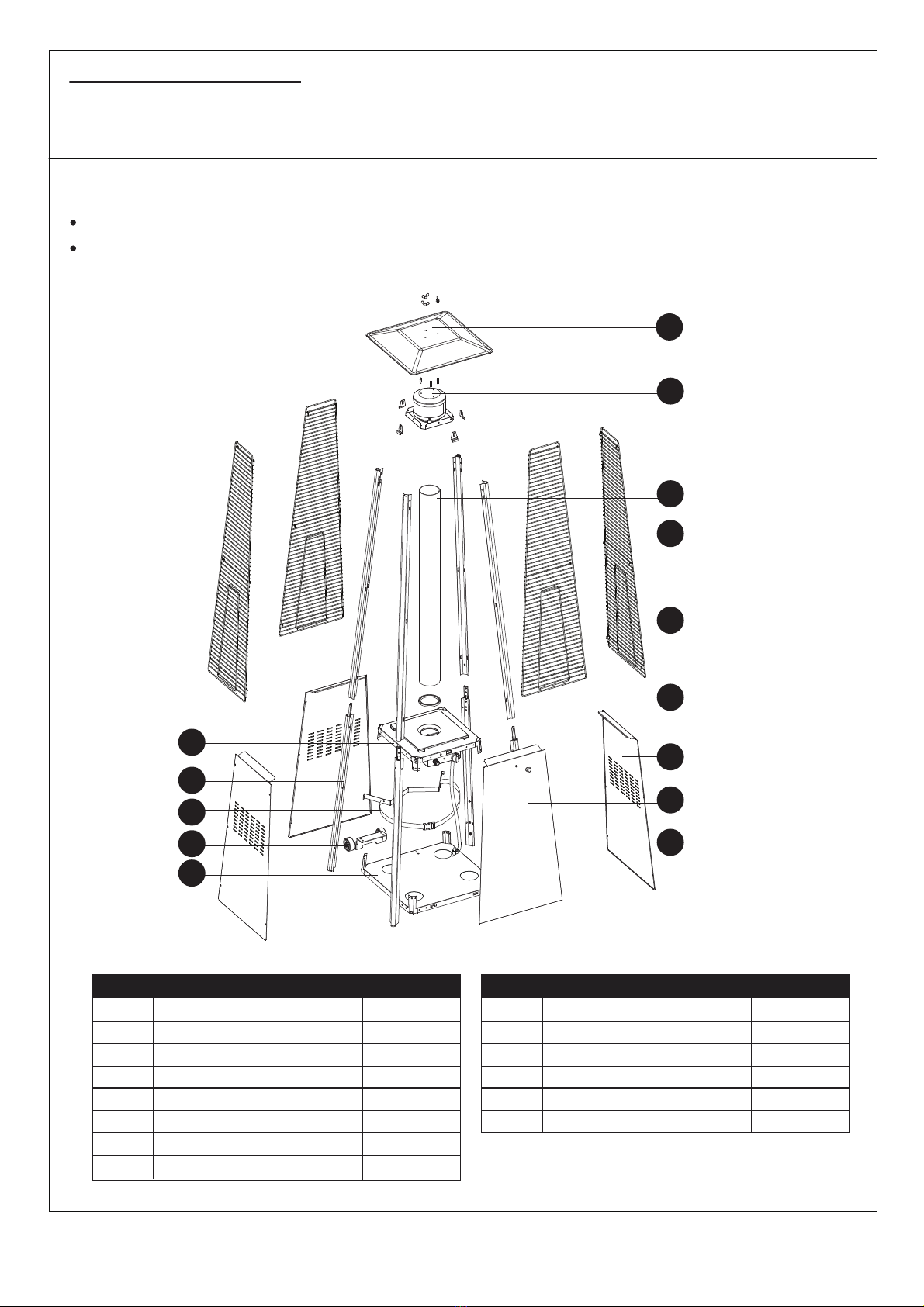
ASSEMBLY PARTS
Tools needed:
Philips screwdriver w/ medium blade
Spray bottle of soap solution for leakage test
Quantity varies according to model purchased. Specifications subject to change
without prior notice.
Parts List:
Reflector
Flame Screen
Glass Tube
Protective Guard
Upper Support
Black Silicone Ring
Side Panel
Front Panel
Block Belt
Lower Support
Control Box Assy
Gas Hose
Wheel Assembly
Bottom Plate
NOITPIRCSEDTRAP YTITNAUQ
1
Flame Screen
1
L
M
N
Gas Hose
Control Box Assy
Lower Support
Block Belt
4
1
1
1
Wheel Assembly
Bottom Plate
NOITPIRCSEDTRAP YTITNAUQ
A
Reflector
1
1B
C
Glass Tube
D
Upper Support
E
1
4
F
G
4
H
Black Silicone Ring
Protective Guard
I
Side Panel
J
Front Panel
K
1
3
1
I
A
B
C
D
E
F
G
H
L
K
J
I
M
N
4
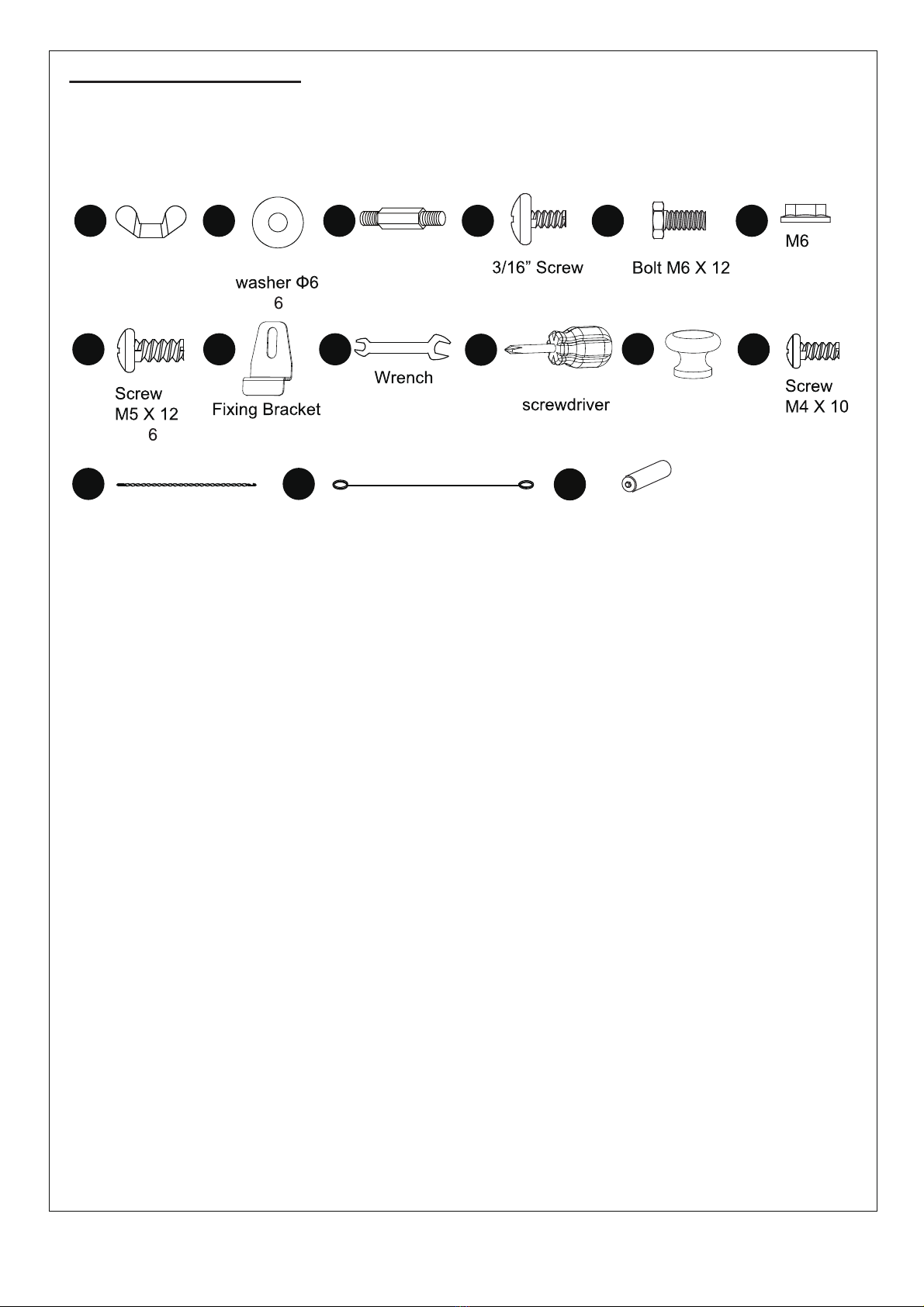
ASSEMBLY PARTS
HARDWARE CONTENTS (shown actual size)
AA BB
Wing nut
Qty. 3 Small flat
Qty.
DD EE
JJ
Qty. 42
CC
Stud
Qty. 3
Philips
Qty. 1
Qty. 4
FF
GG II
Qty. 4
Qty. 1
HH
Flange
nut
Qty. 4
Qty.
KK
Knob
Qty. 1
MM NN
LL
Qty.1
Chain
Qty.1
Long Stem Lighter
Qty.1
OO
AA Battery (1.5 V)
Qty.1
5
PARTS
Quantity varies according to model purchased. Specifications subject to change
without prior notice.
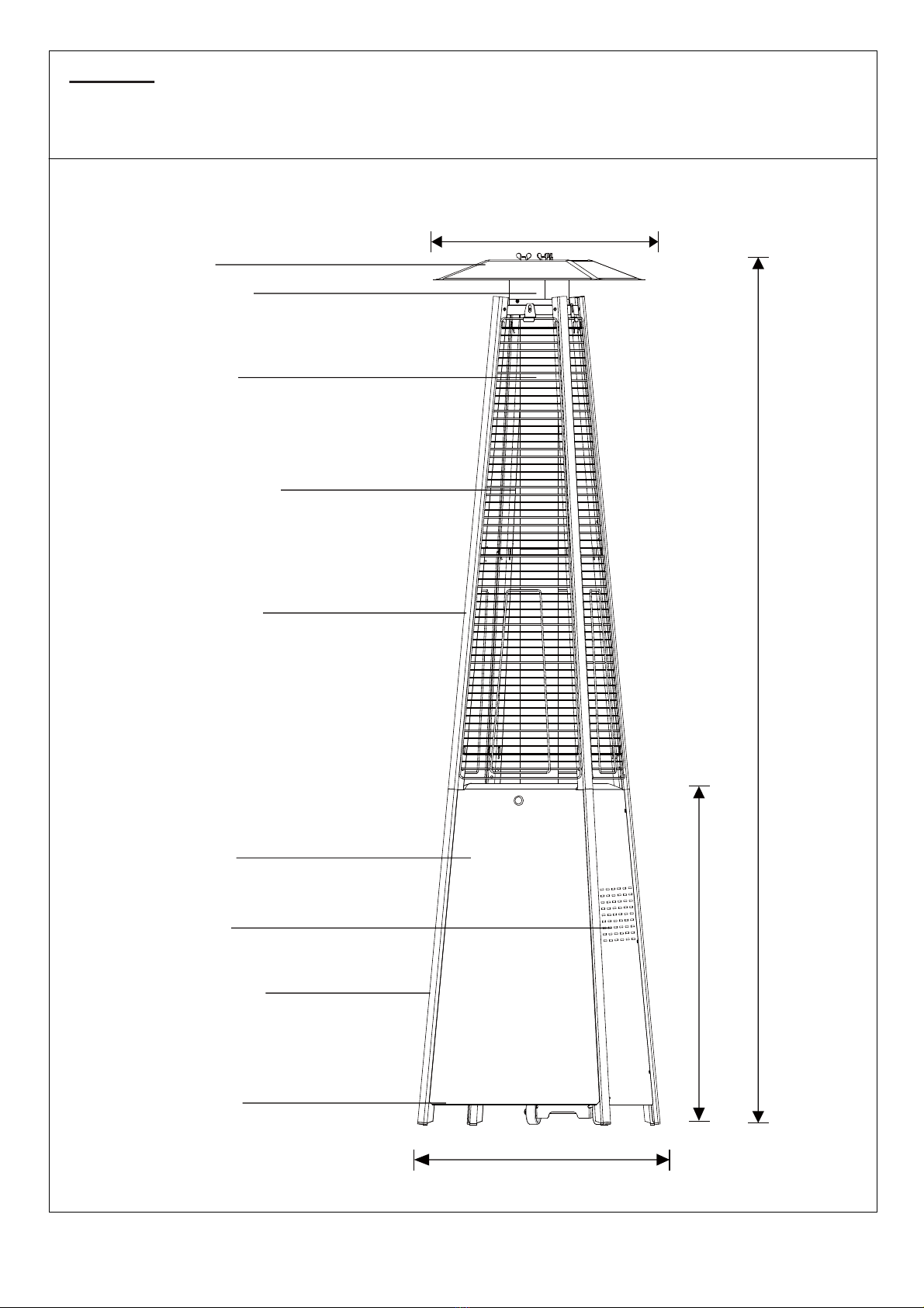
2270 mm
900 mm
650 mm
730 mm
Reflector
Glass Tube
Flame Screen
Protective Guard
Upper Support
Front Panel
Side Panel
Lower Support
Bottom plate

6
ASSEMBLY
IMPORTANT!
Whilst every care is taken in the manufacture of this product, care must be taken
during assembly in case sharp edges are present.
Please read the Important Information section carefully before assembly.
1
2
Hardware Used
EE FF II
1. Assemble the wheel assembly to the bottom plate. Fix the wheel assembly to the bottom
plate using 4pcs bolt M6X12 and 4pcs lange nut M6.
x 4 x 4 Wrench x 1
Bolt M6 X 12 M6 Flange nut
2-1.Unscrew the switch button, load small battery, tighten the switch button.
2-2. Insert the pins of the base to the holes of lower support, press to secure the pins. Using
4pcs screw M5x12 to secure the lower support and base.
Insert the pins of the control box assy to the holes of upper support, press to secure the pins.
Using 4pcs screw 3/16” screw to secure the upper support and control box assy.
Hardware Used
GG JJ
x 4 Philips
screwdriver x 1
Screw M5 X 12 DD x 4
3/16” Screw
M
EE
FF
J
K
DD
GG
OO
AA Battery (1.5 V)

7
3
4
3. Assemble block belt. Fix the block belt to the 2pcs of lower support behind the front door,
using 2pcs screw M5X12.
Hardware Used
JJ x 1
Philips
screwdriver
GG x 2
Screw M5 X 12
4. Assemble the middle support.Insert the 4pcs upper support to the lower support. Secure
them with 8pcs screw 3/16”.
Hardware Used
DD JJ
x 8 x 1
Philips
screwdriver
3/16” Screw
L
GG
D
DD

8
5
6
B
DD
AA
BB
CC
5. Assebmle the flame screen to the upper support.Secure the flame screen to the upper support
using 8pcs screw “3/16”.
Hardware Used
DD JJ
x 8 Philips
screwdriver
3/16” Screw x 1
Hardware Used
6. Assemble the reflector onto the flame screen. Screw the 3pcs stud on the flame screen,
put 3pcs washer 6 onto the top of stud,then put the reflector onto the stud, secure them with
3pcs washer 6 and 3pcs wing nut.
x 3 x 3
x 6
AA BB
Wing nut CC Stud

9
7
8
To aid in installation
place black silicone
ring on the middle
plate and then
install glass tube.
Ensure the rim of
the glass tube sits
firmly in the black
silicone ring.
BLACK SILICONE
RING
E
DD
HH
7. Carefully install the glass tube by lifting up and inserting through the center hole in the
upper plate. Ensure the black silicone ring is attached to the lower edge of the glass tube
as illustrated. Slide the glass tube through the hole of the lower plate cover and onto the
middle plate. Check and ensure that the glass tube is positioned properly and is completely
covering the center hole of the middle plate.
WARNING! The black silicone ring must be in place prior to operating the heater.
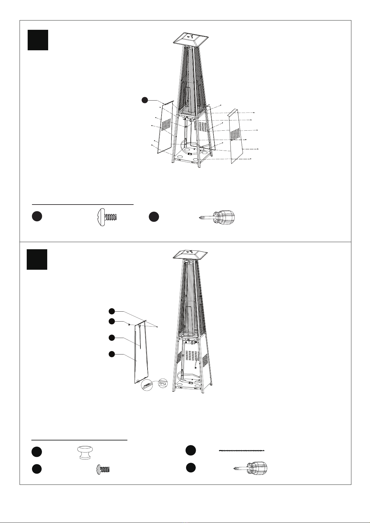
8. Assembly the protective guard.Hang the hooks of the protective guard onto the holes in
supports.
Secure the protective guards with fixing brackets with 4pcs 3/16" screws.
Hardware Used
DD JJ
x 4 Philips
screwdriver
3/16” Screw x 1 HH Fixing
Bracket x 4
10
9
10
9. Attach the three side panels to the heater using 18pcs screw 3/16”.
Note : Do not cover the front side where the control knob is.
Hardware Used
DD JJ
x 18 Philips
screwdriver
3/16” Screw x 1
10. Install the knob to M4x10 screw. Hang the chain to the hole on the control box assy and
put the pothook of front panel to the holes of bottom plate.
Hardware Used
x 1
KK Knob
LL
JJ
x 1
x 1
Philips
screwdriver
Screw M4 X 10 x 1
MM Chain
DD
KK
LL
H
MM
11
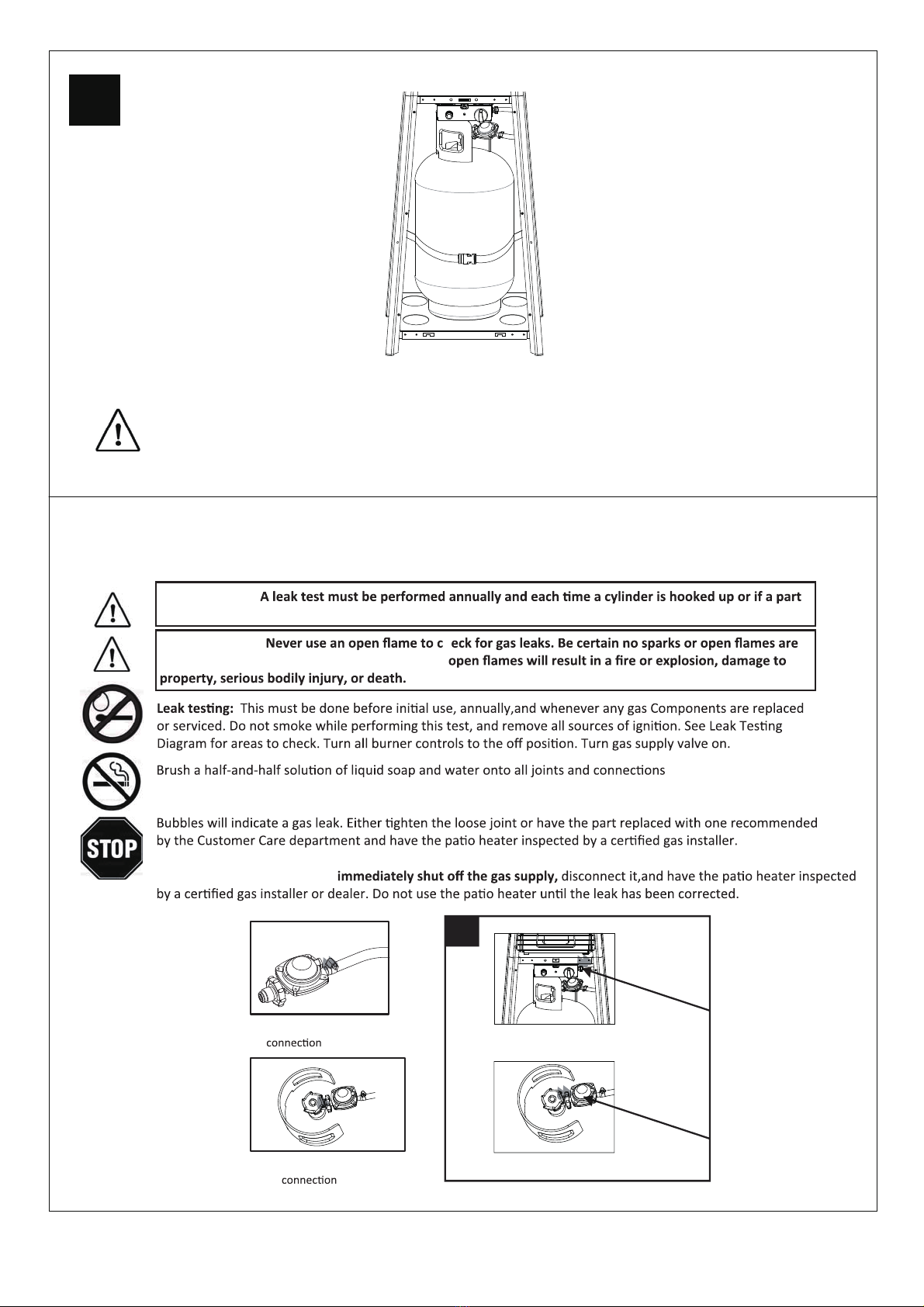
11
11. Propane Only-Proper Hose Connection.
WARNING! Ensure the hose does not contact any high temperature surfaces,or it may
melt and leak causing a fire.
After the cylinder is placed inside the heater, secure the cylinder with block belt tightly.
12. Leak Check.
12
Regulator / Cylinder
Hose / Regulator
WARNING!
of the gas system is replaced.
WARNING! h
in the area while you check for leaks. Sparks or
of the regulator, hose, manifolds and valves.
If the leak cannot be stopped,
12
Gas connections on the heater are leak tested at the factory prior to shipment. A
complete gas tightness check must be performed at the installation site due to
possible mishandling in shipment or excessive pressure being applied to the
heater.
xMake a soap solution of one part liquid detergent and one part water. The soap
solution can be applied with a spray bottle, brush or rag. Soap bubbles will appear
in case of a leak.
xThe heater must be checked with a full cylinder.
xMake sure the safety control valve is in the OFF position.
xTurn the gas supply ON.
xIn case of a leak, turn off the gas supply. Tighten any leaking fittings, then turn the
gas supply on and recheck.
xNever leak test while smoking.
LEAKAGE TEST

13
CAUTION
PLEASE READ CAREFULLY THE FOLLOWING SAFETY GUIDELINES BEFORE
OPERATION.
x Do not use the patio heater for indoors, as it may cause personal injury or
property damage.
xThis outdoor heater is not intended to be installed on recreational vehicles and/or
boats.
xInstallation and repair should be done by a qualified service person.
x Improper installation, adjustment, alteration can cause personal injury or
property damage.
xDo not attempt to alter the unit in any manner.
x Never replace or substitute the regulator with any regulator other than the
factory-suggested replacement.
xDo not store or use gasoline or other flammable vapors or liquids in the heater
unit.
xThe whole gas system, hose, regulator, pilot or burner should be inspected for
leaks or damage before use, and at least annually by a qualified service person.
xAll leak tests should be done with a soap solution. Never use an open flame to
check for leaks.
xDo not use the heater until all connections have been leak tested.
xTurn off the gas valve immediately if smell of gas is detected.Turn Cylinder Valve
OFF. If leak is at Hose/Regulator connection: tighten connection and perform
another leak test. If bubbles continue appearing should be returned to hose’s
place of purchase. If leak is at Regulator/Cylinder Valve connection: disconnect,
reconnect, and perform another leak check. If you continue to see bubbles after
several attempts, cylinder valve is defective and should be returned to cylinder’s
place of purchase.
xDo not transport heater while it’s operating.
x Do not move the heater after it has been turned off until the temperature has
cooled down.
xKeep the ventilation opening of the cylinder enclosure free and clear of debris.
xDo not paint the radiant screen, control panel or top canopy reflector.
xControl compartment, burner and circulation air passageways of the heater must
be kept clean. Frequent cleaning may be required as necessary.
xThe LP tank should be turned off when the heater is not in use.
xCheck the heater immediately if any of the following occurs:
- The heater does not reach temperature.
- The burner makes popping noise during use (a slight noise is normal when the
burner is extinguished).
- Smell of gas in conjunction with extreme yellow tipping of the burner flames.
xThe LP regulator/hose assembly must be located out of pathways where people
may trip over it or in area where the hose will not be subject to accidental damage.
xAny guard or other protective device removed for servicing the heater must be
replaced before operating the heater.
14
x Adults and children should stay away from high temperature surface to avoid
burns or clothing ignition.
xChildren should be carefully supervised when they are in the area of the heater.
x Clothing or other flammable materials should not be hung on the heater or
placed on or near the heater.
xTo close the gas supply at the valve of the gas cylinder or the regulator after use;
xIn the event of gas leakage, the appliance shall not be used or if alight, the gas
supply shall be shut off and the appliance shall be investigated and rectified
before it is used again;
xTo check the hose at least once per month,each time the cylinder is changed, or
each time before long time no use. If it shows signs of cracking, splitting or other
deterioration it shall be exchanged for new hose of the same length and of the
equivalent quality;
x The use of this appliance in enclosed areas can be dangerous and is
PROHIBITED;
x Read the instructions before using this appliance. The appliance must be
installed in accordance with the instructions and local regulations.
x For connection of hose and regulator,and connection of regulator and hose,
please refer to photo showed above.
xRemove plastic wrap from any part before lighting.
xNever cover a heater until it has completely cooled.
xIf you have any queries regarding these instructions, contact your local dealer.
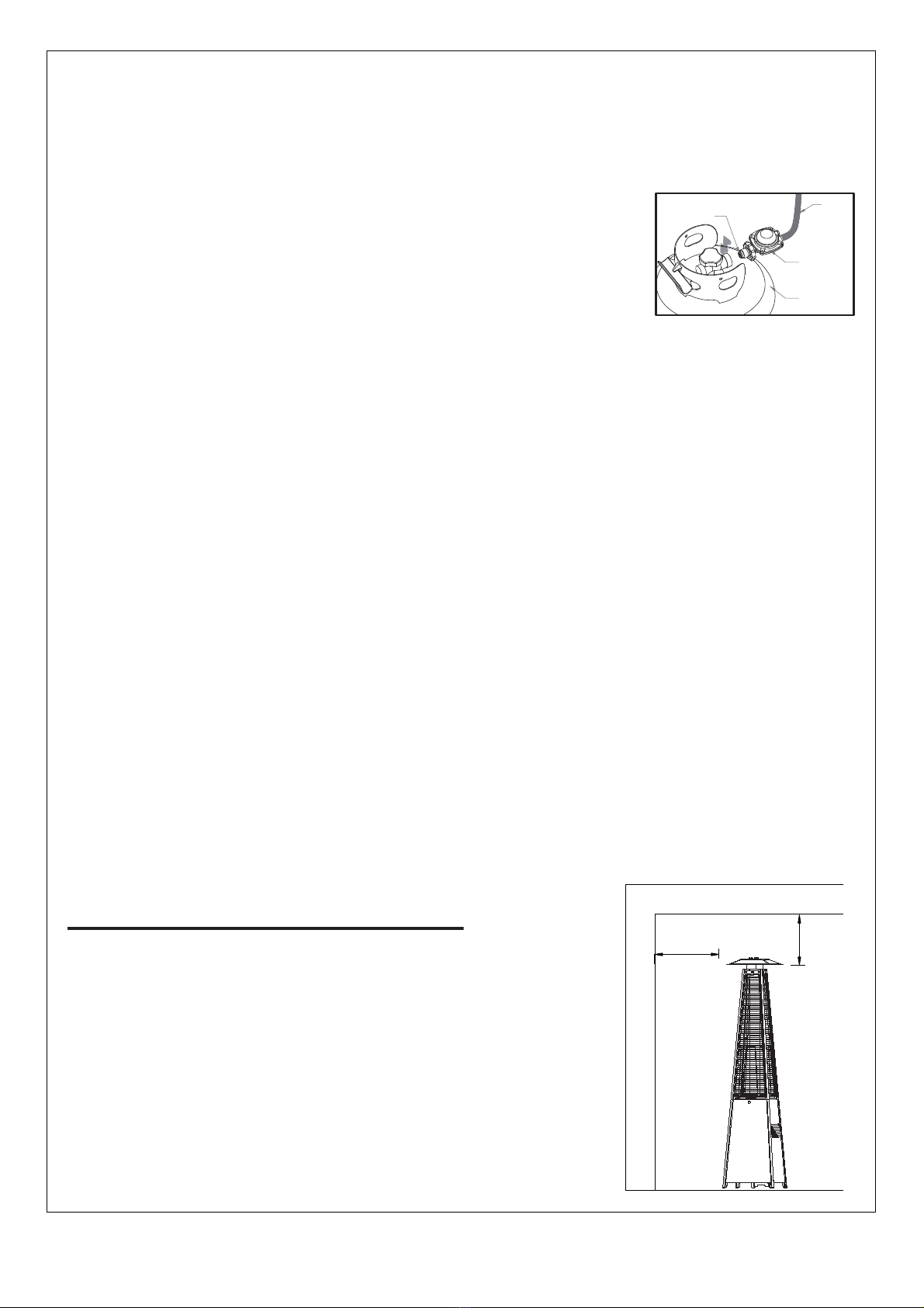
x To change the gas cylinder in a amply ventilated area,
away from any ignition source (candle, cigarettes, other
flame producing appliances, ...);
x To check that the regulator seal is correctly fitted and
able to fulfill its function showed as photo right;
x To not obstruct the ventilation holes of the cylinder
housing;
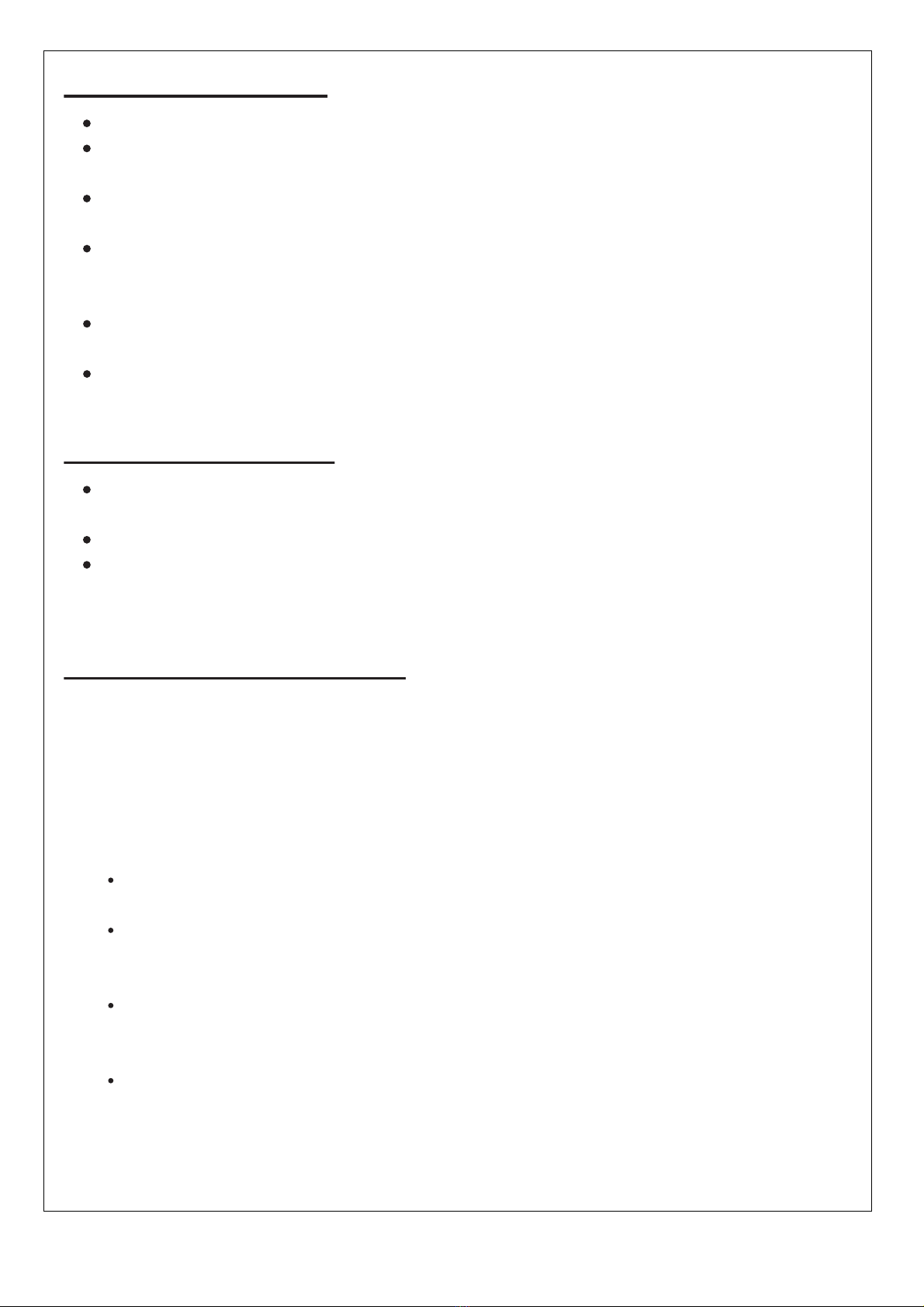
HEATER STAND AND LOCATION
xThe heater is primarily for outdoor use only. Always
ensure that adequate fresh air ventilation is provided.
x Always maintain proper clearance to combustible
materials, i.e. top 100 cm and sides 100 cm minimum.
xHeater must be placed on level firm ground.
x Never operate heater in an explosive atmosphere
like in areas where gasoline or other flammable
liquids or vapors are stored.
xTo protect heater from strong wind, anchor the base
securely to the ground with screws.
Hose/ Regulator connection and
Regulator / Cylinder connection
seal hose
regulater
cylinder
CEILING
WALL
100 cm
100 cm
15
GAS REQUIREMENTS
Use propane or butane gas only.
The pressure regulator and hose assembly to be used must conform to local
standard codes.
The installation must conform to local codes, or in the absence of local codes,
with the standard for the storage and handling of liquid petroleum gases.
A dented, rusted or damaged propane tank may be hazardous and should be
checked by your tank supplier. Never use a propane tank with a damaged valve
connection.
The propane tank must be arranged to provide for vapor withdrawal from the
operating cylinder.
Never connect an unregulated propane tank to the heater.
CLEANING AND CARE
Wipe off powder coated surfaces with soft, moist rag. Do not clean heater with
cleaners that are combustible or corrosive.
Remove debris from the burner to keep it clean and safe for use.
Cover the burner unit with the optional protective cover when the heater is not in
use.
OPERATION AND STORAGE
TO TURN ON THE HEATER
1. Turn on the valve on the gas supply cylinder completely.
2.
Press and turn the variable control knob to PILOT position(counter-clockwise 90°).
3. Press down the variable control knob and hold for 60 seconds. While holding
down the variable control knob, press the igniter button several times until the pilot
flame lights. Release the variable control knob after the pilot flame lights.
Note:
If a new tank has just been connected, please allow at least one minute for the
air in the gas pipeline to purge out through the pilot hole.
When lighting the pilot flame make sure that the variable control knob is
continuously pressed down while pressing the igniter button. Variable control
knob can be released after the pilot flame lights.
Pilot flame can be watched and checked from the small round window with
sliding lid located at the bottom of the flame screen(to the left or right side of the
controller)
If the pilot flame does not light or it goes out, repeat step 3.
4. After the pilot flame lights, turn the variable control knob to maximum position
and leave it there for 5 minutes or more before turning the knob to desired
temperature position.

16
TO TURN OFF THE HEATER
1. Turn the variable control knob to PILOT position.
2. Press and turn the variable control knob to OFF position.
3. Turn off the valve on the gas supply cylinder completely.
Storage
1. Always close the gas valve of the gas cylinder after use or in case of a
disturbance.
2. Remove the pressure controller and the hose.
3. Check the tightness of the gas valve and for damage. If you suspect a damage,
have it changed by your gas dealer.
4. Never store liquid gas cylinder in a sub-terrain, or at places without adequate
air ventilation.
OFF: the heater stop work
HI: maximum temperature position
LO: minimum temperature position
lgniter
Igniter Variable control knob

17
CHARACTERISTICS AND SPECIFICATIONS
A. Construction and characteristics
xTransportable terrace/garden heater with tank housing
xCasing in steel with powder-coating or stainless steel
xGas hose connections with metal clamp (screw caps for Germany)
xHeat emission from reflector
B. Technical Specifications
xUse propane, butane or their mixtures gas only.
xMax. wattage: 13000 watts
xMin. wattage: 5000 watts
xConsumption:
The hose and regulator assembly must conform to local standard codes.
Regulator outlet pressure should meet the corresponding appliance category
in B. Specification.
The appliance requires approved hose in 0.6m length.
xUsing the proper regulator according to outlet pressure of regulator as showed
in the table above.
C. Table of injector
x
x
x
The regulator must comply with the requirements of EN 16129:2013.
The hose must comply with the requirements of EN 16436-1:2014.
Read the intructions before installation and use.
Keep the instructions for future reference.
APPLIANCE CATEGORY:
TYPES OF GAS: Butane Propane
GAS PRESSURE: 28-30mbar 37 mbar 30 mbar 50mbar 37mbar
30mbar 37 mbar 30 mbar 50mbar 37mbar
Butane, propane
or their mixtures Butane, propane
or their mixtures Butane, propane
or their mixtures
OUTLET PRESSURE
OF REGULATOR:
3+(28-30/37) 3B/P(30)
I3B/P(50)
I3B/P(37)
I
I
APPLIANCE CATEGORY:
TYPES OF GAS: Butane Propane
GAS PRESSURE: 28-30mbar 37 mbar 30 mbar 50mbar 37mbar
TOTAL HEAT
INPUT (Hs): (Qn) 13kW
INJECTOR SIZE:
The marking for example 1.88 on the injector indicates that the size of injector is 1.88mm
1.88 mm for main burner
0.18 mm for pilot burner
1.55 mm for main burner
0.18 mm for pilot burner
1.65 mm for main burner
0.18 mm for pilot burner
Butane, propane
or their mixtures Butane, propane
or their mixtures Butane, propane
or their mixtures
3B/P(30)
I3B/P(50)
I3B/P(37)
I
3+(28-30/37)
I
946g/h 929g/h 946g/h
GAS CONSUMPTION:
COUNTRY OF
DESTINATION: GB,IE

18
PROBLEMS CHECK LIST
PROBLEM PROBABLE CAUSE SOLUTION
Pilot will not light Gas valve may be OFF Turn the gas valve ON
Tank fuel empty Refill LPG tank
Opening blocked Clean or replace opening
Air in supply system Purge air from lines
Loose connections Check all fittings
Pilot will not stay on Debris around pilot Clean dirty area
Loose connections Tighten connections
Thermocouple bad Replace thermocouple
Gas leak in line Check connections
Lack of fuel pressure Tank near empty. Refill LPG tank.
Burner will not light Pressure is low Tank near empty. Refill LPG tank.
Opening blocked Remove and clean
Control not ON Turn valve to ON
Thermocouple bad Replace thermocouple
Pilot light assembly bent Place pilot properly
Not in correct location Position properly and retry
Outback International UK Ltd
Unit 4, Sigeric Business Park
Holme Lacy Road, Hereford, HR2 6NS

19
OUTBACK® WARRANTY
OUTBACK® heater are warranted for a period of one (1) year from the date of purchase to
the original purchaser against defects in materials and workmanship, OUTBACK® will
supply replacements for defective parts free of charge provided that:
xThe product has not been used for trade, professional or hire purposes.
xThe product has not been subjected to misuse or neglect, including fat fires and flare ups
or use of a faulty or incorrect regulator.
xThe product has not sustained damage through foreign objects, substances or accidents.
xThe care and maintenance instructions given in your Outback manual have been followed.
If the product includes one or a number of parts or accessories, only the defective accessory
or part will be replaced i.e. Hose, Regulator, Electric Ignitor and Reflector.
Fat fires are not covered under warranty.
Any warrany & guarantee claims shall be rendered void in the event of improper use of the
heater or the use of non approved fuels, discolouration , rusting or slight deformation of
parts exposed directly to the flames (burner) do not impair the function of the heater and do
not form a basis for any claims.
This warranty is offered as an extra benefit and is in addition to the customers’ statutory
rights.
OUTBACK® does not in any way warranty the gas cylinder.
In the unlikely event that you experience problems with this heater, please fill in our warranty
form at:
http://www.outbackbarbecues.com/warranty-form
One of our colleagues will be in contact with you shortly.
HELPLINE NUMBER: 0345 388 6032
For reference and correspondence, record
your serial number here.
(See sticker on side of barbecue body.)
Serial No.__________________
This number may be required when ordering
spare parts or accessories. A part reference
number may also be required where
applicable.
Table of contents
Other Outback Patio Heater manuals


Popular Patio Heater manuals by other brands

Provida Varme
Provida Varme MATRIX PVMA2000 SLV BT Safety instructions and operation manual

Andersen & Stokke
Andersen & Stokke Woven 966688 Assembly and operation instructions

Thermo
Thermo THI 2000 Safety instructions and operation manual

Outdoor Leisure
Outdoor Leisure TD100 owner's manual

Endless Summer
Endless Summer EWT700SP owner's manual

Blumfeldt
Blumfeldt 10029834 manual


Amazon
Amazon Caroline instructions

Endless Summer
Endless Summer ES4000COMM owner's manual

Calcana
Calcana PH Series Specifications, Installation, Operation Service and Spare Parts Manual

SunGlo
SunGlo PSA 265 Installation, operation & maintenance manual

Blumfeldt
Blumfeldt Heatspot manual

Cello
Cello 502328308 instruction manual