Outback OUT370663/PH500 User manual

Assembly and Operating Instructions for Outback®
Stainless Steel Column Heater
0063
17
Drawings are not to scale.
Specifications subject to change
without prior notice.
FOR YOUR SAFETY
If you smell gas:
1. Shut off gas to the appliance.
2. Extinguish any open flame.
3. If odor continues, immediately call your
gas supplier or your fire Department.
FOR YOUR SAFETY
1. Do not store or use gasoline or other flammable
vapors and liquids in the vicinity of this or any
other appliance.
2.An LP cylinder not connected for use shall not be
stored in the vicinity of this or any other appliance.
OUT370663/PH500
WARNlNG SAFETY RULES
PLEASE READ THE FOLLOWING SAFETY RULES PRlOR
TO OPERATION OF THE HEATER
FOR YOUR SAFETY
If you smell gas:
1ˊShut off gas to the appliance.
2ˊExtinguish any open flame.
3ˊIf odor continues, immediately call your gas supplier or your fire
Department.
FOR YOUR SAFETY
1.Do not store or use gasoline or other flammable vapors
and liquids in the vicinity of this or any other applianceˊ
2.An LP cylinder not connected for use shall not be stored in the
vicinity of this or any other applianceˊ
WARNlNG
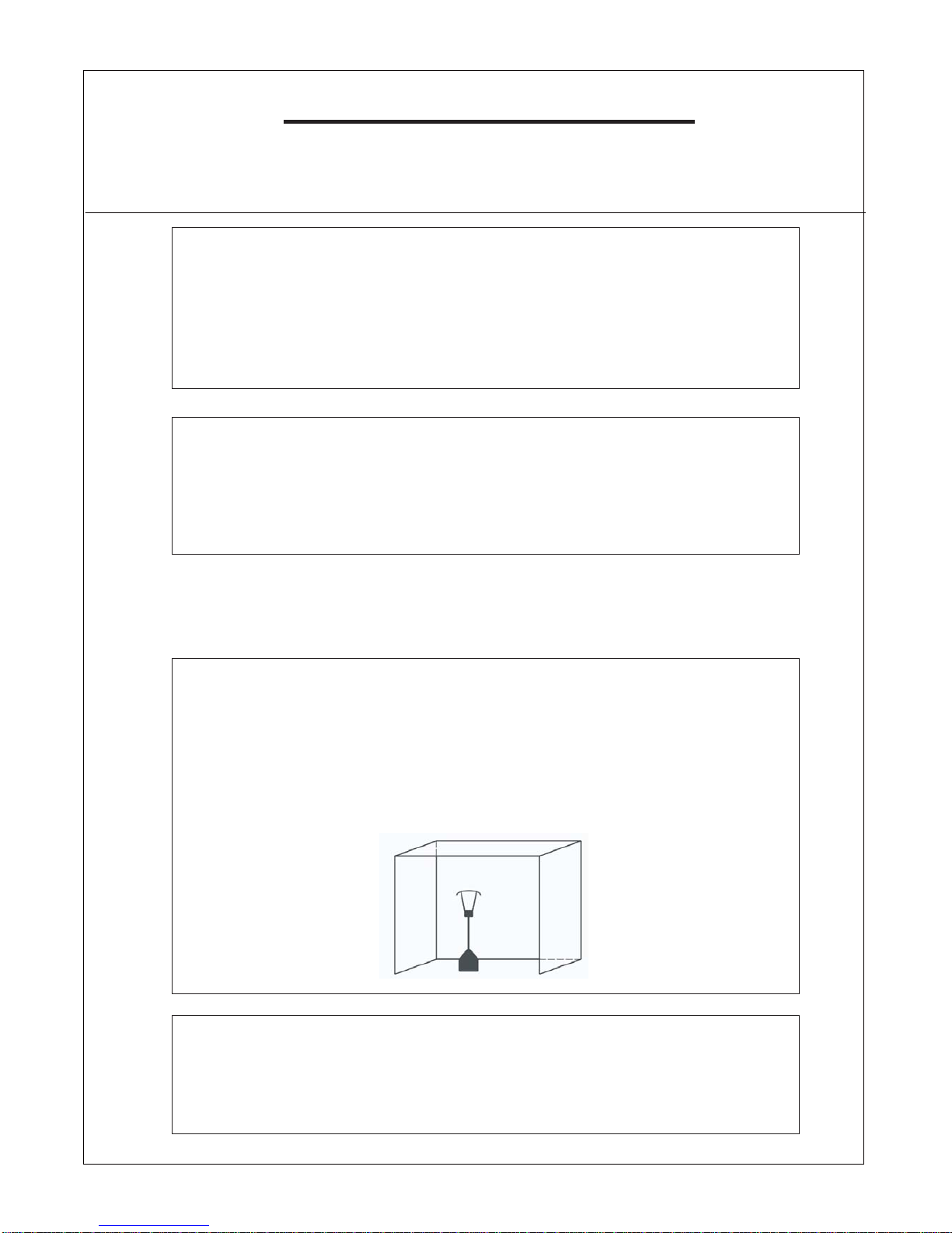
1) For use outdoors or in amply ventilated areas.
2) An amply ventilated area must have a minimum of 25 % of the
surface area open.
3) The surface area is the sum of the walls surface.
WARNING˖Improper installation, adjustment, alteration, service
or maintenance Can cause injury or property damage. Read the
installation, operating and maintenance instructions thoroughly
before installing or servicing this equipment.

warning
Read the instructions before installation and use.
-This appliance must be installed and the gas cylinder stored in
accordance with the regulations in force;
-Do not obstruct the ventilation holes of the cylinder housing;
-Do not move the appliance when in operation;
-Shut off the valve at the gas cylinder or the regulator before moving
the appliance;
-The tubing or the flexible hose must be changed within the
prescribed intervals;
-Use only the type of gas and the type of cylinder specified by the
manufacturer;
The LP tank used with your patio heater must meet the following
requirements:
Purchase LP tanks only with these required measurements:
(31.8cm) (diameter) x 58 cm) (tall) with 15kg capacity maximum.
-In case of violent wind particular attention must be taken against
tilting of the appliance; Keep the appliance at least 1m from the gas
cylinder.
A regulator(compliees with EN16129:2013 and the national regulation)
of the correct pressure corresponding to the appliance category.
Use 30mbar regulator for butane/propane under the category I3B/P(30).
Use 30mbar regulator for butane under the category I3+(28-30/37).
Use 37mbar regulator for propane under the category I3+(28-30/37).
Use 50mbar regulator for butane/propane under the category I3B/P(50).
It's recommended to use flexible hose that approved by EN16436:2014.
i
TABLE OF CONTENTS
Caution ………………………………………………………. 1
Heater Stand and Location ………………………………… 2
Gas Requirements ………………………………………….. 2
Leakage Test ………………………………………………… 2
Operation and Storage ……………………………………... 3
Cleaning and Care ………………………………………….. 4
Parts and Specifications ..………………………………….. 4
Assembly Parts and Procedures ………………………….. 6
Problems Check List ………………………………………... 12
-1-
CAUTION
PLEASE READ CAREFULLY THE FOLLOWING SAFETY GUIDELINES BEFORE OPERATION.
Do not use the patio heater for indoors, as it may cause personal injury or property damage.
This outdoor heater is not intended to be installed on recreational vehicles and/or boats.
Installation and repair should be done by a qualified service person.
Improper installation, adjustment, alteration can cause personal injury or property damage.
Do not attempt to alter the unit in any manner.
Never replace or substitute the regulator with any regulator other than the factory-suggested replacement.
Do not store or use gasoline or other flammable vapors or liquids in the heater unit.
The whole gas system, hose, regulator, pilot or burner should be inspected for leaks or damage before
use, and at least annually by a qualified service person.
All leak tests should be done with a soap solution. Never use an open flame to check for leaks.
Do not use the heater until all connections have been leak tested.
Do not transport heater while it’s operating.
Do not move the heater after it has been turned off until the temperature has cooled down.
Keep the ventilation opening of the cylinder enclosure free and clear of debris.
Do not paint the radiant screen, control panel or top canopy reflector.
Control compartment, burner and circulation air passageways of the heater must be kept clean.
Frequent cleaning may be required as necessary.
The LP tank should be turned off when the heater is not in use.
Check the heater immediately if any of the following occurs:
- The heater does not reach temperature.
- The burner makes popping noise during use (a slight noise is normal when the burner is extinguished).
- Smell of gas in conjunction with extreme yellow tipping of the burner flames.
The LP regulator/hose assembly must be located out of pathways where people may trip over it or in
area where the hose will not be subject to accidental damage.
Any guard or other protective device removed for servicing the heater must be replaced before operating the heater.
Adults and children should stay away from high temperature surface to avoid burns or clothing ignition.
Children should be carefully supervised when they are in the area of the heater.
Cl
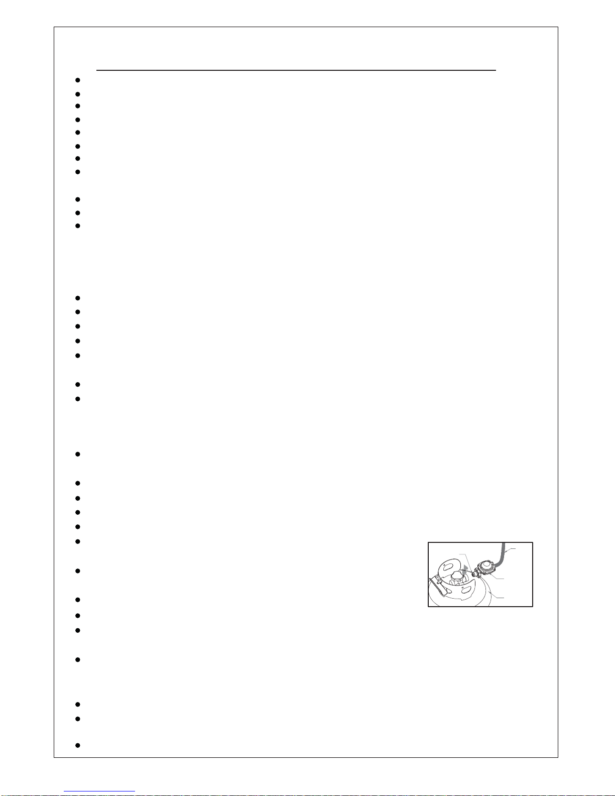
To change the gas cylinder in a amply ventilated area, away from any ignition
source (candle, cigarettes, other flame producing appliances, ...);
To check that the regulator seal is correctly fitted and able to fulfill its function
showed as photo right;
To not obstruct the ventilation holes of the cylinder housing;
To close the gas supply at the valve of the gas cylinder or the regulator after use;
In the event of gas leakage, the appliance shall not be used or if alight, the gas supply
shall be shut off and the appliance shall be investigated and rectified before it is used again;
To check the hose at least once per monthˈeach time the cylinder is changedˈor each time before long time no use.
If it shows signs of cracking, splitting or other deterioration it shall be exchanged for new hose of the same length and of the
equivalent quality;
The use of this appliance in enclosed areas can be dangerous and is PROHIBITED;
Read the instructions before using this appliance. The appliance must be installed in accordance with the instructions and
local regulations.
For connection of hose and regulator,and connection of regulator and hose, please refer to photo showed above.
othing or other flammable materials should not be hung on the heater or placed on or near the heater.
T
Regulator connection: tighten connection and perform another leak test. If bubbles continue appearing
should be returned to hose’s place of purchase. If leak is at Regulator/Cylinder Valve connection: disconnect,
reconnect, and perform another leak check. If you continue to see bubbles after several attempts, cylinder
valve is defective and should be returned to cylinder’s place of purchase.
urn off the gas valve immediately if smell of gas is detected. Turn Cylinder Valve OFF.If leak is at Hose/
Hose/ Regulator connection and
Regulator / Cylinder connection
seal hose
regulater
cylinder

-2-
HEATER STAND AND LOCATION
The heater is primarily for outdoor use only. Always ensure that
adequate fresh air ventilation is provided.
Always maintain proper clearance to non protected combustible materials
i.e. top 100 cm and sides 100 cm minimum.
Heater must be placed on level firm ground.
Never operate heater in an explosive atmosphere like in areas where
gasoline or other flammable liquids or vapors are stored.
To protect heater from strong wind, anchor the base securely to the
ground with screws.
CEILING
WALL
100 cm
100 cm
GAS REQUIREMENTS
Use propane, butane or their mixtures gas only.
The pressure regulator and hose assembly to be used must conform to local standard codes.
The installation must conform to local codes, or in the absence of local codes, with the standard for the
storage and handling of liquid petroleum gases.
A dented, rusted or damaged tank may be hazardous and should be checked by your tank
supplier. Never use a tank with a damaged valve connection.
The tank must be arranged to provide for vapor withdrawal from the operating cylinder.
Never connect an unregulated tank to the heater.
LEAKAGE TEST
Gas connections on the heater are leak tested at the factory prior to shipment. A complete gas tightness
check must be performed at the installation site due to possible mishandling in shipment or excessive
pressure being applied to the heater.
Make a soap solution of one part liquid detergent and one part water. The soap solution can be applied
with a spray bottle, brush or rag. Soap bubbles will appear in case of a leak.
The heater must be checked with a full cylinder.
Make sure the safety control valve is in the OFF position.
Turn the gas supply ON.
In case of a leak, turn off the gas supply. Tighten any leaking fittings, then turn the gas supply on and re-
check.
Never leak test while smoking.

regulator
Off: the heater stop work
Hi: maximum temperature position
Lo: minimum temperature position
1. Fully close gas valve.
2. Turn control knob clockwise to OFF position.
Variable control knob
Pointer
Warning˖check that no broken on the glass is found before operation.
1. Depress and turn control knob clockwise to OFF position.
2. Fully open gas valve.
3. Depress control knob and turn knob counterclockwise to IGNITE position, then to PILOT position
(You should hear a clicking sound).
4. Keep the control knob depressed last for 60 seconds,then turn the control knob back to ‘OFF’position.
5.Repeat step 3 several times until the pilot lights.
NOTE: If the pilot light has not ignited, turn heater control knob to OFF position, fully close gas valve,
wait 5 minutes, then repeat steps 2–4 of the Lighting Instructions.
6. Push in and turn the control knob to LOW position, then release control knob. If you want a higher
temperature,push in the control knob and turn counterclockwise to HIGH position.
LOW
HIGH
PILOT
OFF
I
G
N
I
T
E
P
u
s
h
t
o
t
u
r
n
CLEANING AND CARE
•Wipe off powder coated surfaces with soft, moist rag. Do not clean heater with cleaners that
are combustible or corrosive.
•Remove debris from the burner to keep it clean and safe for use.
•Cover the burner unit with the optional protective cover when the heater is not in use.
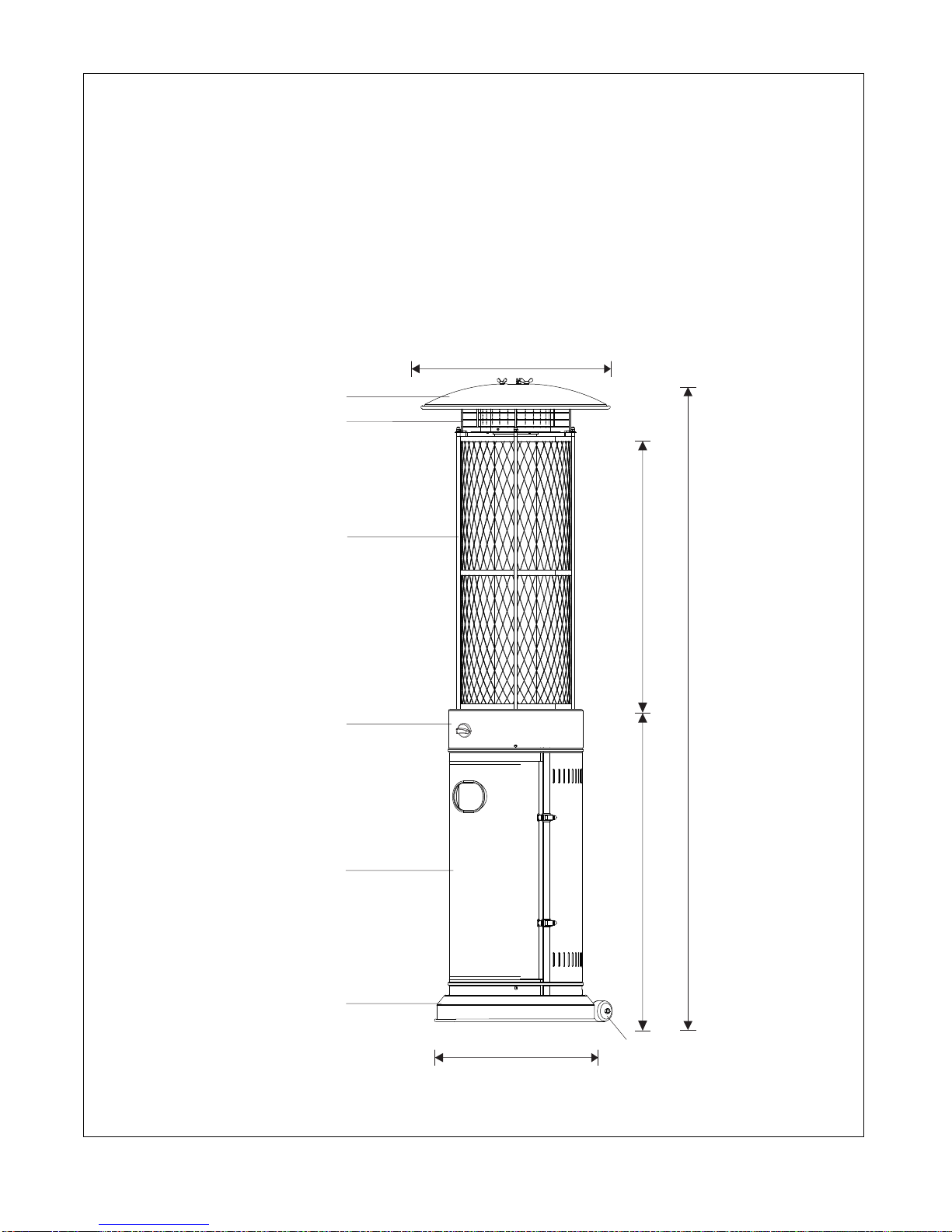
PARTS AND SPECIFICATIONS
- 4 -
1830 mm
890 mm 770 mm
535 mm
460 mm
Reflector
Upper Protective Mesh
Rhombic Protective Mesh
Control Box
Tank housing
Base
Wheel

-5-
A. Construction and characteristics
Transportable terrace/garden heater with tank housing.
Casing in steel with powder-coating or in stainless steel.
Gas hose connections with metal clamp (screw caps for Germany).
Heat emission from reflector.
B. Specifications
Use propane,butane or their mixtures gas only.
Max. wattage: 11000 watts
Min. wattage: 5000 watts
Consumption:
The hose and regulator assembly must conform to local standard codes.
Regulator outlet pressure should meet the corresponding appliance category in B. Specification.
The appliance requires approved hose in 0.6m length.
Using the proper regulator according to outlet pressure of regulator as showed in the table above.
C. Table of injector
APPLIANCE CATEGORY:
TYPES OF GAS: Butane Propane
GAS PRESSURE: 28-30mbar 37 mbar 30 mbar 50mbar 37mbar
TOTAL HEAT
INPUT (Hs): (Qn) 11kW (G30:800g/h; G31:786g/h)
INJECTOR SIZE:
The markingˈfor exampleˈ1.70 on the injectorˈindicates that the size of injector is 1.70mm
1.70 mm for main burner
0.22 mm for pilot burner
1.35 mm for main burner
0.22 mm for pilot burner
1.48 mm for main burner
0.22 mm for pilot burner
APPLIANCE CATEGORY:
TYPES OF GAS: Butane Propane
GAS PRESSURE: 28-30mbar 37 mbar 30 mbar 50mbar 37mbar
30mbar 37 mbar 30 mbar 50mbar 37mbar
Butane, propane
or their mixtures Butane, propane
or their mixtures Butane, propane
or their mixtures
Butane, propane
or their mixtures Butane, propane
or their mixtures Butane, propane
or their mixtures
OUTLET PRESSURE
OF REGULATOR:
3+(28-30/37) I
I
3+(28-30/37)
I
I
3B/P(30)
I3B/P(30)
3B/P(50)
I3B/P(50)
I3B/P(37)
I3B/P(37)

-6-
ASSEMBLY PARTS
Tools needed:
Philips screwdriver w/ medium blade
Spray bottle of soap solution for leakage test
Parts List:
Upper Protective Mesh
NOITPIRCSEDTRAP QUANTITY
A
Reflector
1
B 1
Mesh
C 1
D
Heating Body
E
Gas Hose
F
1
1
G
H
1
Base
Cylinder Housing
Wheel
1
1
Reflector
Upper Protective Mesh
Heating Body
Cylinder Housing
Base
Wheel
A
B
D
F
G
Mesh C
Gas Hose E
H
-7-
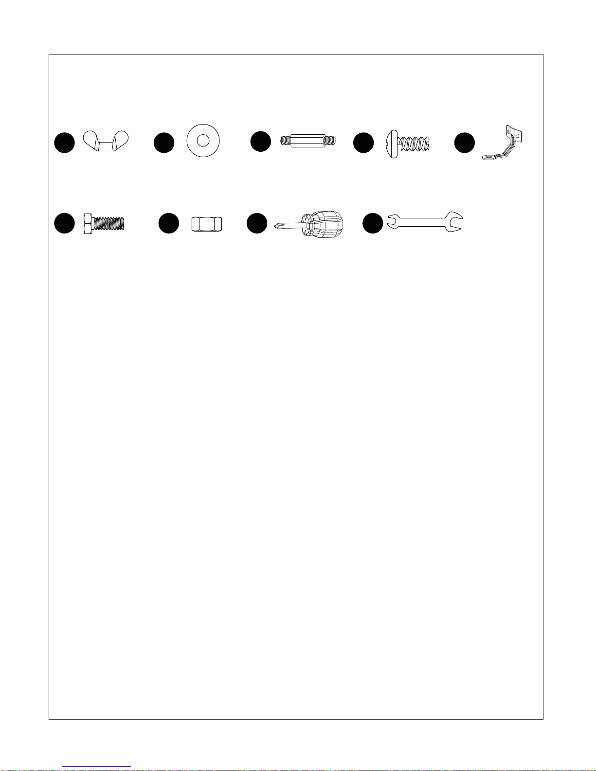
ASSEMBLY PARTS
HARDWARE CONTENTS (shown actual size)
AA BB DD
CC
Wing nut
Qty. 3 Washer Φ6
Qty. 15 Screw M5 X 10
Qty. 11
Stud
Qty. 3
Philips
screwdriver
Qty. 1
Wrench
Qty. 1
II
EE
Ground Fixer
Qty. 3
FF
Bolt M6 x 10
Qty. 6
GG HH
Nut M6
Qty. 6
-8-
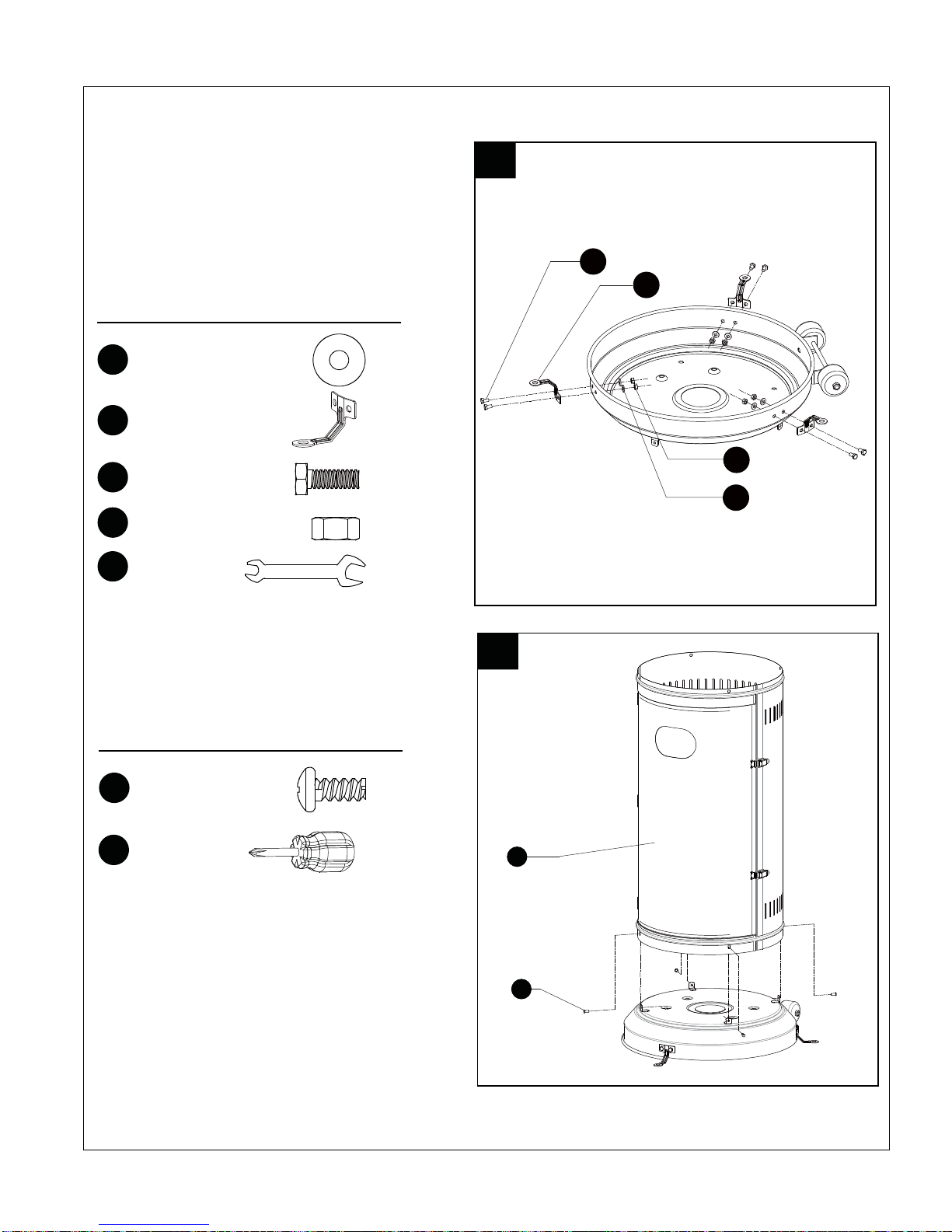
ASSEMBLY PROCEDURES
Hardware Used
HH
2. Assemble the tank housing.
Secure the tank housing to the base using
4pcs screw M5X10.
x 1
Philips
screwdriver
DD x 4
Screw M5X10
2
1
F
DD
Hardware Used
1. To protect heater from strong wind, anchor
the base securely to the ground with screws.
Reverse the base, fix the ground fixer to the
base with bolt M6X10 and washer Φ6 like
picture shows. Secure the ground fixer with
nut M6 Fix another two ground fixer with
bolts and nuts, and reverse the base.
BB x 6
Washer Φ6
EE x 3
Ground Fixer
FF x 6
Bolt M6X10
GG x 6
Nut M6
II x 1
Wrench
FF EE
BB
GG

-9-
Hardware Used
4. Assemble the mesh.
Secure the mesh to the Heating Body using
3pcs screw M5X10.
DD
HH
x 3
x 1
Philips
screwdriver
Screw M5X10
Hardware Used
3. Assemble the heating body.
Secue the heating body to the tank housing
using 4pcs screw M5X10.
DD
HH
x 4
x 1
Philips
screwdriver
Screw M5X10
3
D
DD
4C
DD
-10-
Hardware Used
6. Assemble the reflector.
a. Screw 3pcs stud to the top of mesh, using
3pcs washerΦ6 to the bottom and 3pcs
washerΦ6 to the top.
b. Put the reflector on the stud and secure
them using 3pcs wing nut and 3pcs
washer.
x 3
x 3
x 9
AA
BB
Wing nut
Washer Φ6
CC Stud
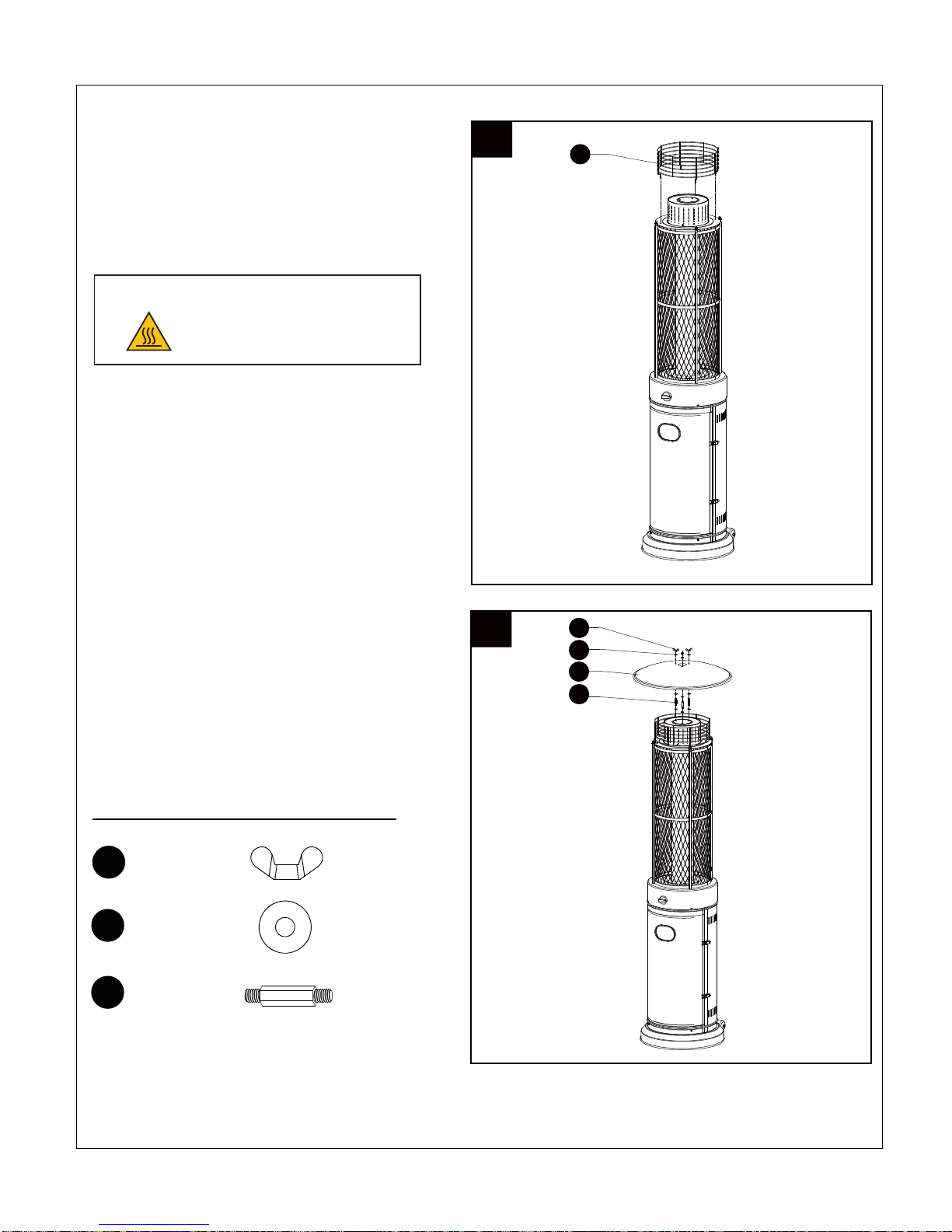
5. Assemble the upper protective mesh
to the heating body directly.
CAUTION: Do not hang clothing or any
other flammable materials from the heater,
or place on or near the heater. HOT! DO
NOT TOUCH!
CAUTION-HOT SURFACE
HOT WHILE IN OPERATION
DO NOT TOUCH
KEEP CHILDREN, CLOTHING
FURNITURE AND FLAMMABLES AWAY
5B
6AA
BB
CC
A

-11-
7. Connect the gas hose and regulator after
that connect the regulator to the gas cylinder.
WARNING! Ensure the hose does not contact
any high temperature surfaces, or it may melt
and leak causing a fire.
After the cylinder is placed inside the heater, secure
the cylinder with block belt tightly.
8. Leak Check.
7
Regulator / Cylinder
Hose / Regulator
WARNING!
of the gas system is replaced.
WARNING!EĞǀĞƌƵƐĞĂŶŽƉĞŶŇĂŵĞƚŽĐhĞĐŬĨŽƌŐĂƐůĞĂŬƐĞĐĞƌƚĂŝŶŶŽƐƉĂƌŬƐŽƌŽƉĞŶŇĂŵĞƐĂƌĞ
in the area while you check for leaks. Sparks or ŽƉĞŶŇĂŵĞƐǁŝůůƌĞƐƵůƚŝŶĂĮƌĞŽƌĞdžƉůŽƐŝŽŶĚĂŵĂŐĞƚŽ
ƉƌŽƉĞƌƚLJƐĞƌŝŽƵƐďŽĚŝůLJŝŶũƵƌLJŽƌĚĞĂƚŚ
of the regulator, hose, manifolds and valves.
If the leak cannot be stopped, ŝŵŵĞĚŝĂƚĞůLJƐŚƵƚŽīƚŚĞŐĂƐƐƵƉƉůLJ
8

-12-
PROBLEMS CHECK LIST
PROBLEM PROBABLE CAUSE SOLUTION
Pilot will not light Gas valve may be OFF Turn the gas valve ON
Tank fuel empty Refill LPG tank
Opening blocked Clean or replace opening
Air in supply system Purge air from lines
Loose connections Check all fittings
Pilot will not stay on Debris around pilot Clean dirty area
Loose connections Tighten connections
Thermocouple bad Replace thermocouple
Gas leak in line Check connections
Lack of fuel pressure Tank near empty. Refill LPG tank.
B
If the appliance is in case of any defaults or problems of assembly or useˈplease don’t try to modify it by yourselfˈ
contact your supplier or distributor to solve it.
urner will not light Pressure is low Tank near empty. Refill LPG tank.
Opening blocked Remove and clean
Control not ON Turn valve to ON
Thermocouple bad Replace thermocouple
Pilot light assembly bent Place pilot properly
Not in correct location Position properly and retry
13
OUTBACK® WARRANTY
OUTBACK® heater are warranted for a period of one (1) year from the date of purchase to
the original purchaser against defects in materials and workmanship, OUTBACK® will
supply replacements for defective parts free of charge provided that:
xThe product has not been used for trade, professional or hire purposes.
xThe product has not been subjected to misuse or neglect, including fat fires and flare ups
or use of a faulty or incorrect regulator.
xThe product has not sustained damage through foreign objects, substances or accidents.
xThe care and maintenance instructions given in your Outback manual have been followed.
If the product includes one or a number of parts or accessories, only the defective accessory
or part will be replaced i.e. Hose, Regulator, Electric Ignitor and Reflector.
Fat fires are not covered under warranty.
Any warrany & guarantee claims shall be rendered void in the event of improper use of the
heater or the use of non approved fuels, discolouration , rusting or slight deformation of
parts exposed directly to the flames (burner) do not impair the function of the heater and do
not form a basis for any claims.
This warranty is offered as an extra benefit and is in addition to the customers’ statutory
rights.
OUTBACK® does not in any way warranty the gas cylinder.
In the unlikely event that you experience problems with this heater, please fill in our warranty
form at:
http://www.outbackbarbecues.com/warranty-form
One of our colleagues will be in contact with you shortly.
HELPLINE NUMBER: 0345 388 6032
For reference and correspondence, record
your serial number here.
(See sticker on side of barbecue body.)
Serial No.__________________
This number may be required when ordering
spare parts or accessories. A part reference
number may also be required where
applicable.
Table of contents
Other Outback Patio Heater manuals


Popular Patio Heater manuals by other brands

Endless Summer
Endless Summer ENDLESS SUMMER EWTR720SP owner's manual

Heat-N-Glo
Heat-N-Glo PATIO CAMPFIRE Installation & operating instructions

Clatronic
Clatronic THS 3541 instruction manual

Heat Outdoors
Heat Outdoors Athena Plus+ Safety instructions and operation manual

Kratki
Kratki UMBRELLA user manual

HEATSTRIP
HEATSTRIP THH-AA Series product manual


