Outback PH04 User manual

Patio Heaters
Outback® Patio Heaters
A regulator of an approved type is
required to operate this unit. A
regulator of 28-30mbar must be
used for butane and 37mbar for
propane. For more details on
compatible regulators for your
patio heater, please contact your
local gas supplier.
WARNING
• For outdoor use only.
• Read instructions before using the appliance. Failure to follow instructions
could result in death, serious bodily injury, and/or property loss.
• Warning: accessible parts may be very hot. Keep young children away.
• Do not move the appliance during use.
• Turn off the gas supply at the gas bottle after use.
• Any modification of the appliance, misuse, or failure to follow the instructions
may be dangerous and will invalidate your warranty. This does not affect your
statutory rights.
• Retainthese instructions for future reference.
• Leak test annually. Check the hose connections are tight and leak test each time
you reconnect the gas bottle.
FOR YOUR SAFETY
If you smell gas:
1. Shut off gas to the appliance.
2. Extinguish any open flame.
3. If odour continues, discontinue use and
contact your local dealer.
FOR YOUR SAFETY
1. Do not store or use petrol or other flammable
vapours or liquids in the vicinity of this or any
other appliance.
2. A gas bottle not connected for use shall not be
stored in the vicinity of this or any other
appliance.
Photographs are not to scale.
Specifications subject to change
without prior notice. 0359
2
A12
A3
A6
A7
A9
A13
A11
A4
A5
A15
A1
A10
A14 A16
A8
A17
A2
B10
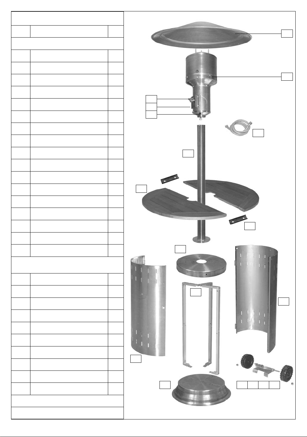
A. Parts List
Code Part Qty
Heater Components
A1 Reflector 1
A2 Burner Assembly 1
A3 Knob* 1
A4 Control Panel* 1
A5 Ignition Pushbutton* 1
A6 Hose* 1
A7 Post 1
A8 Table Half 2
A9 Door 1
A10 Base Top 1
A11 Base Support 3
A12 Base Hull 1
A13 Base 1
A14 Wheel Locknut 2
A16 Wheel Axle Washer 2
A17 Wheel Axle Bracket 1
Hardware (For more details,
see Hardware Reference diagram)
B1 M6x20 Hex Bolt 8
B2 Large Plain Washer 9
B3 M6 Hex Locknut 8
B4 M4x15 Flat Screw 6
B5 Small Plain Washer 6
B6 M4 Hex Nut 6
B7 1/4UNCx12 Bolt 8
B8 Spacer 1
B9 Latch 1
*Pre-Assembled Component
Specifications subject to change without notice.
A15 Wheel 2
B10 Table bracket 2

3
B. Hardware Reference Diagram
Specifications subject to change without prior notice.
Part B1 (7pcs), Part B2 (7pcs), Part B3 (7pcs)
Part B4 (6pcs), Part B5 (6pcs)
Part B6 (6pcs)
Part B7 (8pcs)
Part B1 (1pc)
Part B2 (2pcs)
Part B3 (1pc)
Part B8 (1pc)
Part B9 (1pc)

4
C. Assembly
nTOOLS NEEDED FOR ASSEMBLY:
Medium size flat blade or Philips/crosspoint screwdriver, adjustable spanner or metric spanner set.
nRemove all packing materials from the components before assembly. Two people are required to perform
assembly of the patio heater as it involves handling of large, heavy parts which may be difficult for one person to
handle. Please read the instructions thoroughly and carefully before assembly and use.
3
Remove the four base screws from the base (A13),
align the holes of the wheel bracket (A17) with the
holes in the base, fix with the four base screws and
slide the wheel axle washers (A16) and wheels
(A15) onto the axle and secure with locknuts (A14).
Assemble the base hull (A12) using the flat screws
(B4), small plain washers (B5) and M4 hex nuts (B6).
The hull is secured using only the two side base
supports. The additional 3 slots in the base hull must
be positioned at the top. Now fully tighten the base
support screws shown in step 2.
Remove the six base support screws from the
base and assemble the base supports (A11). The
additional 3 slots in the base hull must be
positioned at the top. WARNING: Do not tighten
the screws fully until step 3 is completed.
A13
A14
A16
A17
A11
Align the three holes of the base top (A10) with the
holes in the base supports, and secure the cover by
threading large plain washers (B2) onto each bolt
(B1), insert the bolts through the aligned holes, and
secure with locknuts (B3).
Align the four holes of the post (A7) with the holes in
the base top (A10). Thread large plain washers (B2)
onto each bolt (B1), insert the bolts through the
aligned holes, and secure with locknuts (B3).
A12 B4
B5
B6
A10
B1
B2
B3
B1 B2 B3A7
A10
4
1 2

5
Remove all washers and acorn nuts from the studs on top of the burner head (A2). Place a
washer on each stud and slot the reflector (A1) onto the burner head studs. Secure with the
remaining 4 washers and acorn nuts.
5
Fit the door latch (B9) by inserting an M6x20 bolt
(B1) through a large plain washer (B2) and spacer
(B8). Place the door latch over the spacer, insert
the bolt through another plain washer (B2), base
hull and secure with an M6 locknut (B3).
A1
Remove the 4 screws and washers from the lower
flange of the burner head. NB - Hose joints should be
leak tested during assembly as detailed on P. 8.
Feed the gas hose down through the post (A7) into
the base assembly. Secure the burner head to the
post using the 4 screws and washers.
6
7

6
ASSEMBLY IS NOW COMPLETE.
PROCEED TO THE NEXT PAGE FOR
INSTRUCTIONS ON OPERATION AND
MAINTENANCE.
Position one table half (A8) onto the base top. Ensure
the notches in the underside of the table correspond
with the bolt heads of the base top.
From inside the hull, secure the table half (A8) to the
base top using the round head bolts (B7).
Repeat steps 8 and 9 for remaining half of table.
Attach the door (A9).
Confirm the heater control knob is turned to
the PILOT position and connect the gas hose
to your regulator and the regulator to your
gas bottle following your regulator supplier
instructions.
A8
B7
A8
From inside of the tables, secure the table bracket
(B10) to the two table half together using the table
bracket bolts (B7).
A8
B10
Note: please go to step 11 if the table is not
included for the model you purchased.
8 9
10 11
7
Model Gas Bottle Size
Outback®
Patio Heater Propane 10kg
D. For Your Safety
If you smell gas:
• Turn off gas supply at bottle.
• Extinguish all naked flames; do not operate
any electrical appliances.
• Ventilate the area.
• Check for leaks as detailed in this manual.
• If odour persists, contact your dealer or gas
supplier immediately.
E. Important Information
Please read these instructions carefully before
assembly and use.
• Retain these instructions for future reference.
• For outdoor use only – do not use indoors.
This appliance should never be used in
basements or below ground level.
• Ensure the heater stands on a firm level
surface.
• Always turn off the gas at the cylinder
whenever the heater is not alight! Turning
the patio heater control knob fully
clockwise does not close off the gas
supply!
• For use with LPG bottled gas only. A fixed
pressure regulator of 28-30mbar must be used
for butane or 37mbar for propane. The use of
an adjustable regulator is dangerous and must
never be used with this heater.
• LP gas cylinders must not be stored or used in
the horizontal position. A leak would be very
serious and liquid could enter the gas line.
• These instructions are only valid if your country
is one of the following listed country codes on
the appliance. If this code is not present on the
appliance, it is necessary to refer to the
technical instructions, which will provide the
necessary information concerning the
modification of the appliance to the conditions
of use for the country.
(Country Codes: DK, FI, NL, NO, SE, BE,
ES, FR,GB, IE, IT, LU, PT, IN, IL, IS, JO, KW,
LB, MY, MX, SA, CZ, CY, EE, GR, HU, LV,
LT, MT, PL, SI)
• Before installation, check that the local
distribution conditions, nature of gas, and
pressure, and adjustment of the appliance are
compatible.
• Do not use heater where the reflector is within
1.5m of any flammable structure or surface or
any other surface that may be affected by heat,
such as glass or plastic.
• Do not move the heater while alight.
• This appliance must not be left unattended
when lit.
• Never operate the heater with the top half
covered (burner head, reflector, etc.)
• Parts of this heater can become very hot –
care must be taken when children, elderly
people, and animals are present.
• When the heater is not alight, always turn off
gas at the bottle or cylinder valve.
• Do not store flammable materials near this
heater.
• Do not use aerosols near this heater.
• Failure to follow the manual’s instructions
could result in serious injury or damage.
• If you have any queries regarding these
instructions, contact your local dealer.
• If the appliance is not alight because the pilot
has become extinguished, the hose will still be
full of gas which may liquefy in cold weather or
leak out if the system is not sound. IT IS
ESSENTIAL THAT THE CYLINDER IS
TURNED OFF AT ALL TIMES WHEN THE
HEATER IS NOT ALIGHT.
• As with other free standing garden equipment,
the patio heater may become unstable during
strong winds. For this reason, we do not
recommend outdoor storage or use during
strong winds. For added safety, the heater can
be secured to the ground using the holes
provided in the base.
• Remove the gas bottle before moving the patio
heater.
F. Gas and Regulator Information
This heater, hose, (and regulator, if included), are
approved for use in the UK. The heater is also
approved for use in other countries as listed in the
Technical Specifications included in the heater
manual. If the heater is intended to be used
outside of the UK, the consumer MUST seek
advice from the local qualified gas supplier as to
the suitability of the heater and with regards to the
correct hose and regulator that they should be
using.
This appliance can use either propane or butane
LPG bottled gas. For optimal performance we
recommend that only propane gas is used.
Propane gas is supplied under a number of
different names and bottle colours. Never store the
gas bottles inside a building. If in doubt, please
consult your gas dealer/distributor.
For optimal performance, we suggest the
following:
8
Suitable regulators for butane must have an outlet
pressure of 28-30mbar. For propane, the regulator
should have an outlet pressure of 37mbar. YOU
MUST HAVE THE PROPER REGULATOR AND
BOTTLE IN ORDER FOR THE HEATER TO
OPERATE SAFELY AND EFFICIENTLY. USE OF
AN INCORRECT OR FAULTY REGULATOR IS
DANGEROUS AND WILL INVALIDATE ANY
WARRANTY. Please consult your local gas dealer
for the most suitable gas bottles and regulators.
G. Installation
G1. Selecting a Location
This heater is for outdoor use only and should be
placed in a well-ventilated area. Ensure that it is
not placed UNDER any combustible surface. Do
not use heater where the reflector is within 1.5m of
any flammable structure or surface that may be
affected by heat, such as glass or plastic. Ensure
the heater stands on a firm, level surface. Keep
this heater away from any flammable materials!
G2. Precautions
Make sure the gas supply bottle is placed level
within the base. Should you need to change the
gas bottle, confirm the gas is turned off at the
cylinder or regulator, and there are no sources of
ignition (cigarettes, open flame, sparks, etc.) near
before proceeding. Hose which can be used with
this heater must conform with BS 3212 Type 2.
Length of hose for use with this heater is 1.40m. If
hose is not supplied with your heater, please
contact an authorised gas supplier or distribution
agent. Ensure that the hose bore and regulator
nozzle are compatible. The hose should be
secured to the regulator nozzle using a Jubilee clip
or similar. Inspect the gas hose to ensure it is free
of any twisting or tension. The hose should hang
freely with no bends, folds, or kinks that could
obstruct free flow of gas. Always inspect the hose
for cuts, cracks, or excessive wear before use. If
the hose is damaged, it must be replaced with
hose suitable for use with LPG and meet the
national standards for the country of use. N.B.-The
date on U.K. orange hose is the date of
manufacture, not the expiry date.
G3. Fixing the Regulator to the Gas Bottle
Confirm the heater control knob is turned fully
clockwise to the “PILOT” position. Connect the
regulator to the gas bottle according to your
regulator and bottle dealer’s instructions.
G4. Leak Testing (To be performed in a well-
ventilated area.)
Confirm the control knob is turned fully clockwise
to the “PILOT” position. Open the gas control at
the cylinder. Check for leaks by brushing a
solution of ½ water and ½ soap over all gas
system joints, including all valve connections, hose
connections and regulator connections. It may be
necessary to disassemble some of the parts in
order to leak test the unit. NEVER USE AN OPEN
FLAME to test for leaks at anytime. If bubbles form
over any of the joints, there is a leak. Turn off the
gas supply and retighten all fittings. Repeat test. If
bubbles form again, do not use the heater. Please
contact your local dealer for assistance. Leak test
upon first receipt, and annually thereafter. Be sure
to reassemblethe unit properly before use.
H. Operation
H1. Warning
• Before proceeding, make certain that you
understand the IMPORTANT INFORMATION
section of this manual.
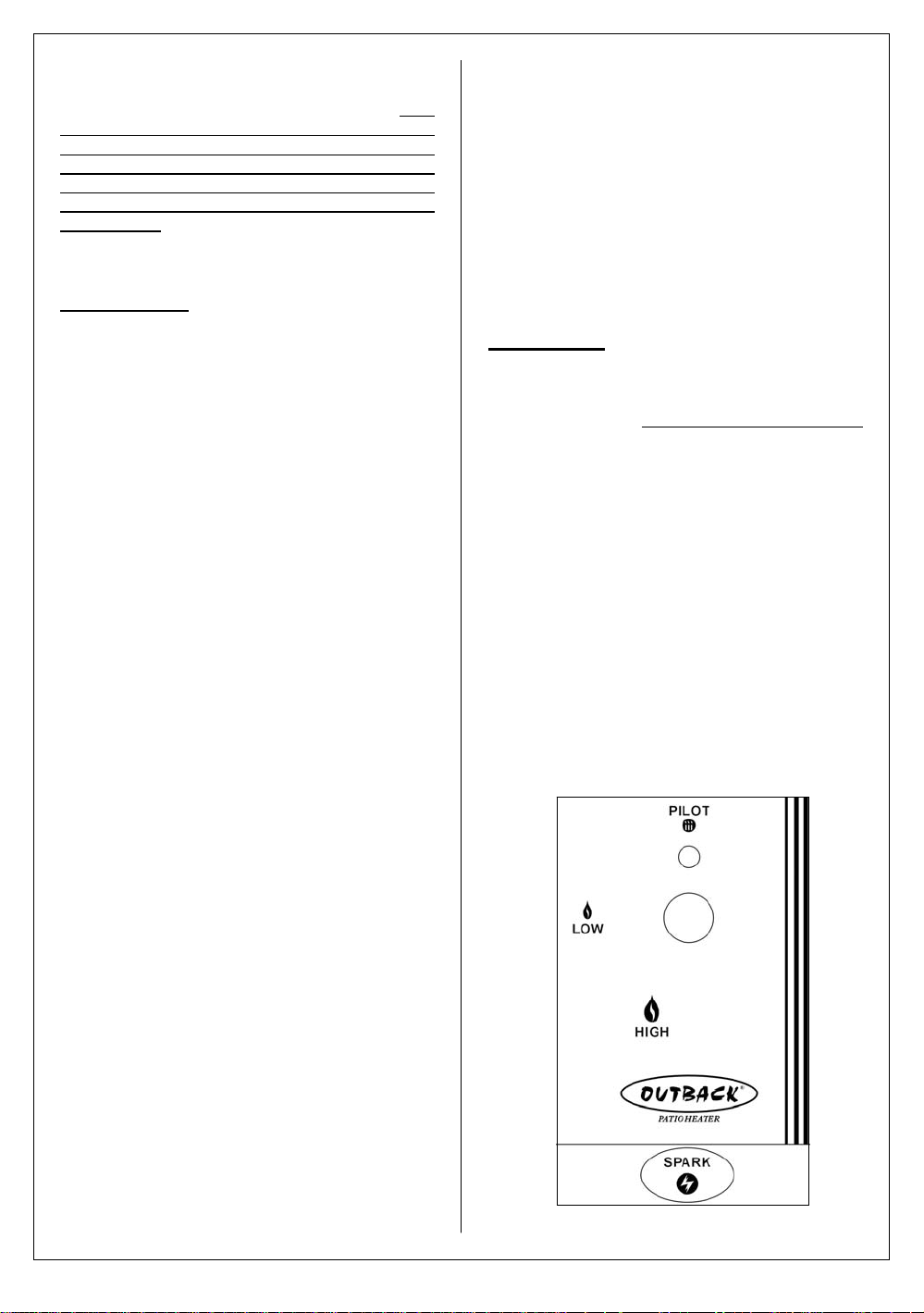
H2. Lighting the Heater (See Diagram 1)
• Open the gas control valve on the gas bottle
or regulator.
• Push in the knob at the“PILOT” position.
• While pressing down the knob at the “PILOT”
position, repeatedly press “SPARK” button to
ignite the pilot.
• Push knob in for a minimum of 10 seconds,
and visually confirm proper lighting of the
pilot. If the pilot fails to light, repeat lighting
sequence and hold knob in for 20 seconds.
(When using with a new cylinder or after
changing a cylinder, you may need to hold the
knob in for as much as one minute in order to
purge all air from the gas train.)
Diagram 1

9
• The control can then be turned in an anti-
clockwise direction to the “LOW” or “HIGH”
position. DO NOT ATTEMPT TO TURN THE
CONTROL KNOB WITHOUT RELEASING
FROM ITS PUSHED-IN POSITION. FAILURE
TO CARRY OUT THIS INSTRUCTION
COULD RESULT IN DAMAGE TO THE
VALVE ASSEMBLY.
• In windy weather, light and operate the heater
in an area protected from the wind. Do not
move the heater while it is alight.
• On the main burner, the flames should ignite
in a circular fashion around the edges of the
burner. Ensure the flames are burning evenly
around the burner.
• The optimal colour of a properly burning flame
is blue with yellow tips.
• If the pilot or main burner fail to light, turn
control knob fully clockwise to the “PILOT”
position, turn gas off at the cylinder and wait 5
minutes before repeating lighting procedure.
• If pilot or main burner STILL fails to ignite, turn
control knob fully clockwise to the “PILOT”
position, turn gas off at the cylinder and wait 5
minutes, then follow the steps in the section
titled ‘Manual Lighting Procedure’.
H3. Manual Lighting Procedure
• Open the gas control valve on the gas bottle
or regulator.
• Insert a lit match through the match-lighting
hole in the mesh of the burner assembly.
Position the match near the pilot.
• Push in the knob at the”PILOT” position.
• Push knob in for a minimum of 10 seconds,
and visually confirm proper lighting of the
pilot. If the pilot fails to light, repeat lighting
sequence and hold knob in for 20 seconds.
(When using with a new cylinder or after
changing a cylinder, you may need to hold the
knob in for as much as one minute in order to
purge all air from the gas train.)
• The control can then be turned in an anti-
clockwise direction to the “LOW” or “HIGH”
position. DO NOT ATTEMPT TO TURN THE
CONTROL KNOB WITHOUT RELEASING
FROM ITS PUSHED-IN POSITION. FAILURE
TO CARRY OUT THIS INSTRUCTION
COULD RESULT IN DAMAGE TO THE
VALVE ASSEMBLY.
• In windy weather, light and operate the heater
in an area protected from the wind. Do not
move the heater while it is alight.
• On the main burner, the flames should ignite
in a circular fashion around the edges of the
burner. Ensure the flames are burning evenly
around the burner.
• The optimal colour of a properly burning flame
is blue with yellow tips.
• If the pilot or main burner fail to light, turn
control knob fully clockwise to the “PILOT”
position, turn gas off at the cylinder and wait 5
minutes before repeating manual lighting
procedure.
• If pilot or main burner STILL fails to ignite, turn
control knob fully clockwise to the “PILOT”
position, turn gas off at the cylinder, and
contact your local authorised gas dealer.
H4. Shut down procedure
• Turn knob fully clockwise to the “PILOT”
position.
• Turn gas off at the cylinder or regulator.
• Let the heater cool down sufficiently before
handling and/or moving.
I. Care and Maintenance
Regularly clean your patio heater between uses
and especially after extended periods of storage.
Ensure the heater control is turned fully clockwise
to the “PILOT” position, the gas is shut off at the
cylinder, and the heater and its components are
sufficiently cool before cleaning. Never douse the
heater with water when its surfaces are hot.
I1. Heater Base and Post
Use a damp cloth or sponge to wipe dirt and grime
away. Do not use any abrasives or solvents, which
can damage the surface paint.
I2. Fixings
All screws and bolts, etc. should be checked and
tightened on a regular basis.
I3. Table
Your patio heater table is manufactured using a
hardwood ideally suited to outdoor use. Its
condition and appearance can be maintained by
applying Teak oil or similar, as required. Hardwood
will naturally weather and change its appearance.
It is quite natural for small cracks to appear on the
surface of the wood.
I4. Storage
Do not leave the patio heater exposed to outside
weather conditions or stored in damp, moist areas.
To save space during long-term storage, the
reflector can be removed by removing the acorn
nuts that hold it in place. Take care to ensure the
shape of the reflector is not damaged or deformed,
as this will affect performance. When using the
heater after extended periods of storage, re-attach
the reflector by fastening it onto the burner head.
The heater should never be operated without the
reflector in place. If the heater is to be stored
indoors, the gas bottle must be disconnected and
left outside. The gas bottle should always be
stored outside, in a dry, well-ventilated area, away
10
from any sources of heat or ignition. Do not let
children tamper with the bottle. Heavy duty
Outback® patio heater covers are available from
your local Outback® stockist.
I5. Service
We recommend your heater is serviced on an
annual basis. Servicing should be carried out by a
qualified Corgi gas technician. During storage in
particular it is possible for insects or foreign
material to get into the burner assembly, main jet
or pilot light assembly and interfere with the
correct operation of the heater. The jet on the pilot
light is also very small and it is the main cause of
the pilot not lighting if it becomes blocked. In
addition, the burner mesh should be brushed to
keep it clear of any deposits.
J. Technical Specifications
For reference and correspondence, record your serial
number here. (See sticker on side of patio heater.)
Serial No._________________________
This number may be required when ordering spare
parts or accessories. A part reference number may
also be required where applicable.
Model Name PH04
CE Approval 0359 359BR216
Heat Input 13.5kW
Gas Consumption 980g/hr
Injector Size 1.93
Gas Types:
Butane or Propane Operating
Pressure:
Butane - 28-30mbar
Propane - 37mbar
Countries of Use I3+(28-30/37) BE, CY, CZ, EE, FR, GR, IE,
IS, IT, LV, LT, LU, PT, SK, ES, CH, GB
I3B/P(30) CY, CZ, DK, EE, FI, GR, LV, LT,
LU, MT, NL, NO, SK, SI, SE, TR
I3B/P(50) AT, DE, HU, SK, CH
I3B/P(36) PL
Dimensions 750mm x 750mm x 2320mm
Net Weight 33.5kg
Burners 1
Published October 2006’
In the unlikely event that you experience problems
with this heater, please contact:
Customer Service
Outback UK
Unit 2 Farleigh Hill
Tovil
Maidstone
Kent
ME15 6RG
Tel: 01622 671771
Fax: 01622 673101
e-mail: customerservice@outbackuk.com
Table of contents
Other Outback Patio Heater manuals


