6
Ramp Model Features
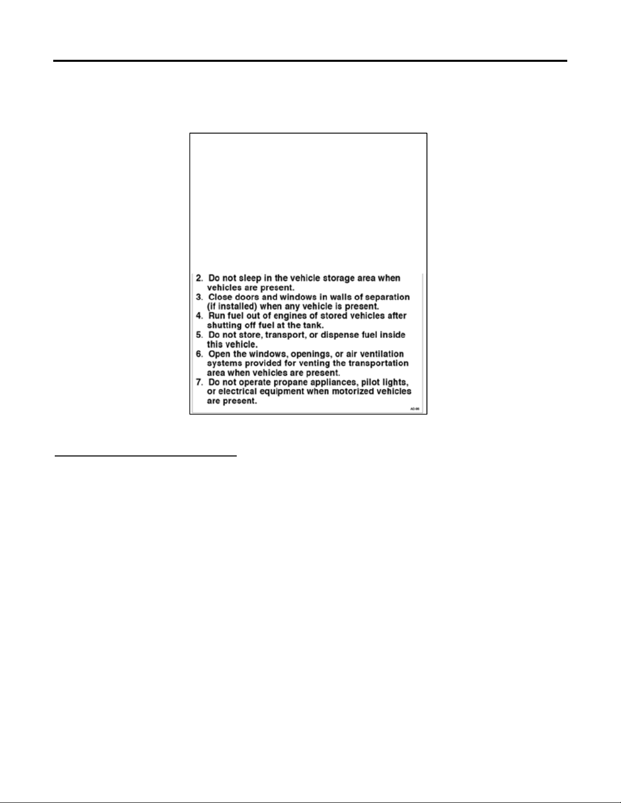
Loading Motorized Vehicles
Always follow the instructions in the owner’s manual for the motorized vehicles you will be hauling. If
not available, the following suggestions provide you with a generalized procedure for loading.
1. Follow the 'Loading Ramp Operation and Procedure' listed above.
2. Shift vehicle into its lowest gear before ascending ramp.
3. Approach straight on, not at an angle. If you are off to one side and the ground is uneven where
the ramp touches the ground, an unbalanced situation can occur.
4. Align front wheels with ramp so that the vehicle will be driven straight in.
5. The operator should apply slight throttle smoothly and climb the ramp at low speed. Too much
or sudden increases in throttle will cause the vehicle to be harder to control and may cause the
vehicle to impact cabinetry inside the RV or flip over backwards.
6. Stop when you have reached the location in which you have planned to secure your vehicle with
the cargo tie-down rings.
7. After loading, close fuel valves on gasoline powered vehicles. Put in park. Turn ignition key off.
Set parking brake. For manual clutch vehicles, leave parked in reverse or low gear with brake
set.
Cargo Tie-Down Rings
The cargo area of your ramp model RV is equipped with cargo tie-down rings that must be used when
transporting heavier items that will likely roll or tip while traveling. Tie-down straps are not included
with your RV and must be purchased separately. Cargo tie-down rings are rated at 2500 lbs. maximum
loading capacity however structural limitations to the RV floor may reduce that maximum rating. Do not
over tighten tie-down straps as this may cause damage to the attachment hardware, floor structure
and cargo. Use tie-down straps rated in excess of the weight of the cargo to be secured. Be sure to attach
and secure each tie-down strap so that it cannot come loose, unfastened, opened or released while the
RV is in motion. Also use edge protection whenever a tie-down strap could be damaged or cut at the
point where it touches a sharp or rough edge of any cargo item.
Top heavy items will likely need additional strapping as they are very likely to tip over when turning,
braking or accelerating. It is important to use enough tie-down straps to secure your load so that it will
not move in any direction. Keep handlebars, mirrors, etc. away from interior walls. Interior walls and
cabinet finishes can be damaged by items working loose and rubbing. This type of damage is not
covered under warranty.
Secure the Load
Some vehicles or equipment may benefit by locating 'chock' blocks in front and rear of its tires to help
minimize any shifting. Adding chocks is strictly an additional safety precaution and does not reduce the
need for strapping the cargo in securely.
Secure the vehicle with tie-downs straps. A minimum of four straps, (one at each corner) is
recommended. The attachments points you select on your equipment must be strong enough to support
the weight of the equipment. If securing ATV, UTV, motorcycle or other vehicle, refer to your vehicles
owner’s manual for specific securement locations. Any attachment to a decorative piece of chrome or
plastic will usually not be a good tie-down point and may cause damage to your equipment and RV.
While transporting, motorized cargo with manual transmissions should be left in first or reverse gear.
Vehicles with automatic transmissions should be left in the 'Park' position.