Owens Corning 313221M Parts list manual

Instructions & Parts
r_256765_313221_39b r_256765_313221_38b
EnergyComplete Sprayer Packages
257125 Heated Package
257126 Heated Package with compressor
See page 4 for a list of models, approvals, and maximum working pressures.
For patent information, see www.graco.com/patents.
EnergyComplete™Sprayer
Manual No:
For use with EnergyComplete Air Infiltration Barrier with Flexible Seal Technology.
Not for use in explosive atmospheres or with flammable materials.
Important Safety Instructions
Read all warnings and instructions in this manual.
Save these instructions.
313221M

2313221M
Contents
Related Manuals . . . . . . . . . . . . . . . . . . . . . . . . . . . 3
Models . . . . . . . . . . . . . . . . . . . . . . . . . . . . . . . . . . . 4
Warnings . . . . . . . . . . . . . . . . . . . . . . . . . . . . . . . . . 5
Overview . . . . . . . . . . . . . . . . . . . . . . . . . . . . . . . . . . 7
Keep Components A and B Separate . . . . . . . . . . 7
Compatible Solvents . . . . . . . . . . . . . . . . . . . . . . . . 7
EnergyComplete Air Infiltration Barrier Temperature
Requirements . . . . . . . . . . . . . . . . . . . . . . . . . . 7
Component Identification . . . . . . . . . . . . . . . . . . . . 8
Controls and Indicators . . . . . . . . . . . . . . . . . . . . . 9
Motor/Pump Control Function Knob . . . . . . . . . . 9
STATUS Indicator . . . . . . . . . . . . . . . . . . . . . . . . 9
Motor Power Switch/Circuit Breaker . . . . . . . . . . 9
Heater Power Switch/Circuit Breaker . . . . . . . . 10
Heater Temperature Controls . . . . . . . . . . . . . . 10
Fluid Temperature Sensors and Displays . . . . . 10
Air Compressor Power Switch/Circuit Breaker . 11
Air Compressor Controls . . . . . . . . . . . . . . . . . . 11
Setup . . . . . . . . . . . . . . . . . . . . . . . . . . . . . . . . . . . . 12
Preheat Hoses . . . . . . . . . . . . . . . . . . . . . . . . . 17
Startup . . . . . . . . . . . . . . . . . . . . . . . . . . . . . . . . . . 18
Spraying/Dispensing . . . . . . . . . . . . . . . . . . . . . . . 19
Pause . . . . . . . . . . . . . . . . . . . . . . . . . . . . . . . . . . . 20
Pressure Relief Procedure . . . . . . . . . . . . . . . . . . 21
Shutdown . . . . . . . . . . . . . . . . . . . . . . . . . . . . . . . . 21
Maintenance . . . . . . . . . . . . . . . . . . . . . . . . . . . . . . 22
Flushing . . . . . . . . . . . . . . . . . . . . . . . . . . . . . . . . . 23
Troubleshooting . . . . . . . . . . . . . . . . . . . . . . . . . . . 25
Status Codes . . . . . . . . . . . . . . . . . . . . . . . . . . 25
Troubleshooting Chart . . . . . . . . . . . . . . . . . . . . 28
Repair . . . . . . . . . . . . . . . . . . . . . . . . . . . . . . . . . . . 32
Before Beginning Repair . . . . . . . . . . . . . . . . . . 32
Recirc/Spray Valves . . . . . . . . . . . . . . . . . . . . . 33
Displacement Pump . . . . . . . . . . . . . . . . . . . . . 34
Control Module . . . . . . . . . . . . . . . . . . . . . . . . . 36
Fluid Heaters . . . . . . . . . . . . . . . . . . . . . . . . . . . 40
Pressure Transducers . . . . . . . . . . . . . . . . . . . . 40
Drive Housing . . . . . . . . . . . . . . . . . . . . . . . . . . 41
Cycle Counter Switch Replacement . . . . . . . . . 42
Electric Motor . . . . . . . . . . . . . . . . . . . . . . . . . . 43
Compressor . . . . . . . . . . . . . . . . . . . . . . . . . . . 44
Motor Brushes . . . . . . . . . . . . . . . . . . . . . . . . . . 46
Fan . . . . . . . . . . . . . . . . . . . . . . . . . . . . . . . . . . 46
Parts . . . . . . . . . . . . . . . . . . . . . . . . . . . . . . . . . . . . 47
Suggested Spare Replacement Parts . . . . . . . . . 56
Accessories . . . . . . . . . . . . . . . . . . . . . . . . . . . . . . 56
Dimensions . . . . . . . . . . . . . . . . . . . . . . . . . . . . . . 57
Technical Data . . . . . . . . . . . . . . . . . . . . . . . . . . . . 58
Graco Standard Warranty . . . . . . . . . . . . . . . . . . . 60
Graco Information . . . . . . . . . . . . . . . . . . . . . . . . . 60

Related Manuals
313221M 3
Related Manuals
The following manuals are for EnergyComplete Sprayer components and accessories. Some are supplied with your
package, depending on its configuration. Manuals are available at www.partnerwithpink.com.
EnergyComplete Spray Gun
Part No. Description
313294 Instruction-Parts Manual
A Side Displacement Pump - White Material
Part No. Description
313123 Instruction-Parts Manual
B Side Displacement Pump - Red Material
Part No. Description
313383 Instruction-Parts Manual
Fluid Heater
Part No. Description
311210 Instruction-Parts Manual
EnergyComplete Compressor Kit
Part No. Description
313457 Instruction-Parts Manual

Models
4313221M
Models
The model no., series letter, and serial no. are located on the back of the EnergyComplete Sprayer. For faster assis-
tance, please have that information ready before calling Customer Service.
* See page 13 for detailed electrical requirements.
All EnergyComplete Sprayer packages are ETL approved.
Package
Sprayer
Model Volts
* Electrical
Connection Package Description
Maximum
Working
Pressure,
psi
(MPa, bar)
Maximum
Air Working
Pressure,
psi
(MPa, bar)
257125 257089 120 V
15 A cord
(motor)
15 A cord
(heaters)
Heated EnergyCom-
plete Sprayer, insulated
3-hose bundle, Energy-
Complete Spray Gun,
circulation kit
2000
(14, 140)
100
(0.7, 7)
257126 256765 120 V
15 A cord
(motor)
15 A cord
(heaters)
15 A cord
(compressor)
Heated EnergyCom-
plete Sprayer, insulated
3-hose bundle, compres-
sor, EnergyComplete
Spray Gun, circulation kit
2000
(14, 140)
100
(0.7, 7)
#ONFORMSTO!.3)5,
3TD#ERTIFIEDTO
#!.#3!3TD
#.O

Warnings
313221M 5
Warnings
The following general warnings are for the setup, use, grounding, maintenance, and repair of this equipment. Addi-
tional, more specific warnings may be found throughout the body of this manual where applicable. Symbols appear-
ing in the body of the manual refer to these general warnings. When these symbols appear throughout the manual,
refer back to these pages for a description of the specific hazard.
WARNING
ELECTRIC SHOCK HAZARD
Improper grounding, setup, or usage of the system can cause electric shock.
• Turn off and disconnect power cord before servicing equipment.
• Use only grounded electrical outlets.
• Use only 3-wire extension cords.
• Ensure ground prongs are intact on sprayer and extension cords.
• Do not expose to rain. Store indoors.
TOXIC FLUID OR FUMES HAZARD
Toxic fluids or fumes can cause serious injury or death if splashed in the eyes or on skin, inhaled, or
swallowed.
• Read MSDS’s to know the specific hazards of the fluids you are using.
• Store hazardous fluid in approved containers, and dispose of it according to applicable guide-
lines.
PERSONAL PROTECTIVE EQUIPMENT
You must wear appropriate protective equipment when operating, servicing, or when in the operating
area of the equipment to help protect you from serious injury, including eye injury, inhalation of toxic
fumes, burns, and hearing loss. This equipment includes but is not limited to:
• Protective eyewear
• Clothing and respirator as recommended by the fluid and solvent manufacturer
•Gloves
• Hearing protection
SKIN INJECTION HAZARD
High-pressure fluid from gun, hose leaks, or ruptured components will pierce skin. This may look like
just a cut, but it is a serious injury that can result in amputation. Get immediate surgical treatment.
• Do not point gun at anyone or at any part of the body.
• Do not put your hand over the spray tip.
• Do not stop or deflect leaks with your hand, body, glove, or rag.
• Do not spray without tip guard and trigger guard installed.
• Engage trigger lock when not spraying.
•FollowPressure Relief Procedure in this manual, when you stop spraying and before cleaning,
checking, or servicing equipment.

Warnings
6313221M
FIRE AND EXPLOSION HAZARD
Flammable fumes, such as solvent and paint fumes, in work area can ignite or explode. To help pre-
vent fire and explosion:
• Use equipment only in well ventilated area.
• Eliminate all ignition sources; such as pilot lights, cigarettes, portable electric lamps, and plastic
drop cloths (potential static arc).
• Keep work area free of debris, including solvent, rags and gasoline.
• Do not plug or unplug power cords, or turn power or light switches on or off when flammable
fumes are present.
• Ground all equipment in work area. See Grounding instructions.
• Use only grounded hoses.
• Hold gun firmly to side of grounded pail when triggering into pail.
• If there is static sparking or you feel a shock, stop operation immediately. Do not use equip-
ment until you identify and correct the problem.
• Keep a fire extinguisher in the work area.
PRESSURIZED ALUMINUM PARTS HAZARD
Do not use 1,1,1-trichloroethane, methylene chloride, other halogenated hydrocarbon solvents or flu-
ids containing such solvents in pressurized aluminum equipment. Such use can cause serious chem-
ical reaction and equipment rupture, and result in death, serious injury, and property damage.
EQUIPMENT MISUSE HAZARD
Misuse can cause death or serious injury.
• This equipment is for professional use only.
• Do not leave the work area while equipment is energized or under pressure. Turn off all equip-
ment and follow the Pressure Relief Procedure in this manual when equipment is not in use.
• Do not exceed the maximum working pressure or temperature rating of the lowest rated system
component. See Technical Data in all equipment manuals.
• Use fluids and solvents that are compatible with equipment wetted parts. See Technical Data in
all equipment manuals. Read fluid and solvent manufacturer’s warnings. For complete informa-
tion about your material, request MSDS from distributor or retailer.
• Check equipment daily. Repair or replace worn or damaged parts immediately with genuine
Graco replacement parts only.
• Do not alter or modify equipment.
• Use equipment only for its intended purpose. Call your Graco distributor for information.
• Route hoses and cables away from traffic areas, sharp edges, moving parts, and hot surfaces.
• Do not kink or over bend hoses or use hoses to pull equipment.
• Keep children and animals away from work area.
• Do not operate the unit when fatigued or under the influence of drugs or alcohol.
• Comply with all applicable safety regulations.
MOVING PARTS HAZARD
Moving parts can pinch or amputate fingers and other body parts.
• Keep clear of moving parts.
• Do not operate equipment with protective guards or covers removed.
• Pressurized equipment can start without warning. Before checking, moving, or servicing equip-
ment, follow the Pressure Relief Procedure in this manual. Disconnect power or air supply.
BURN HAZARD
Equipment surfaces and fluid that’s heated can become very hot during operation. To avoid severe
burns, do not touch hot fluid or equipment. Wait until equipment/fluid has cooled completely.
WARNING

Overview
313221M 7
Overview
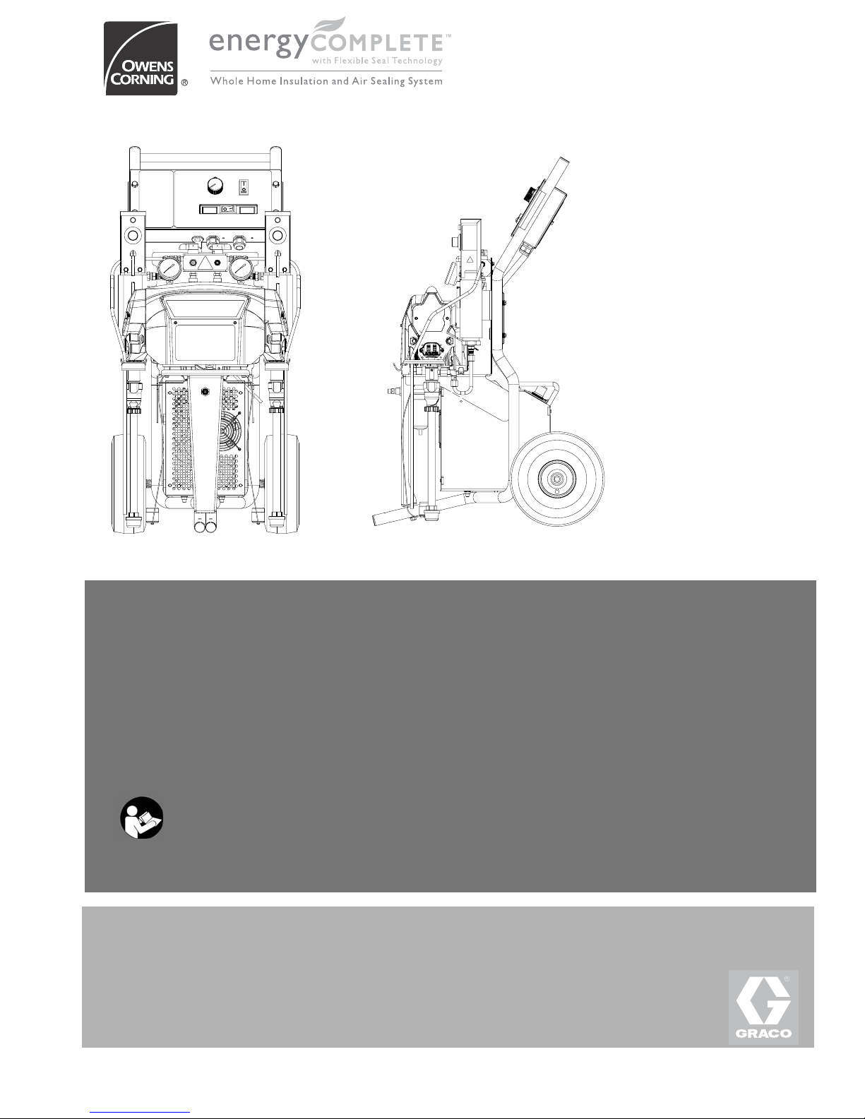
The EnergyComplete Sprayer is a portable, elec-
tric-powered, 4:1 mix ratio proportioner, for use with
EnergyComplete Air Infiltration Barrier with Flexible
Seal Technology by Owens Corning. Materials must be
self-leveling and pourable, and may be applied with
impingement mix spray guns, disposable mixer guns, or
flush-type mix manifolds.
The EnergyComplete Sprayer is siphon-fed from 5 gal-
lon pails that can be mounted on the unit.
Severe duty, positive displacement reciprocating piston
pumps meter fluid flow to the gun for mixing and apply-
ing. When set to recirculation mode, EnergyComplete
Sprayer will circulate fluids back to the 5 gallon pails.
The EnergyComplete Sprayer includes separate ther-
mostatically controlled heaters for each fluid. Digital dis-
plays show the temperatures of the two fluids.
An electronic processor controls the motor, monitors
fluid pressures, and alerts the operator if errors occur.
See STATUS Indicator, page 9, for further information.
For models with a compressor: An air compressor pro-
vides and regulates air pressure for the spray gun.
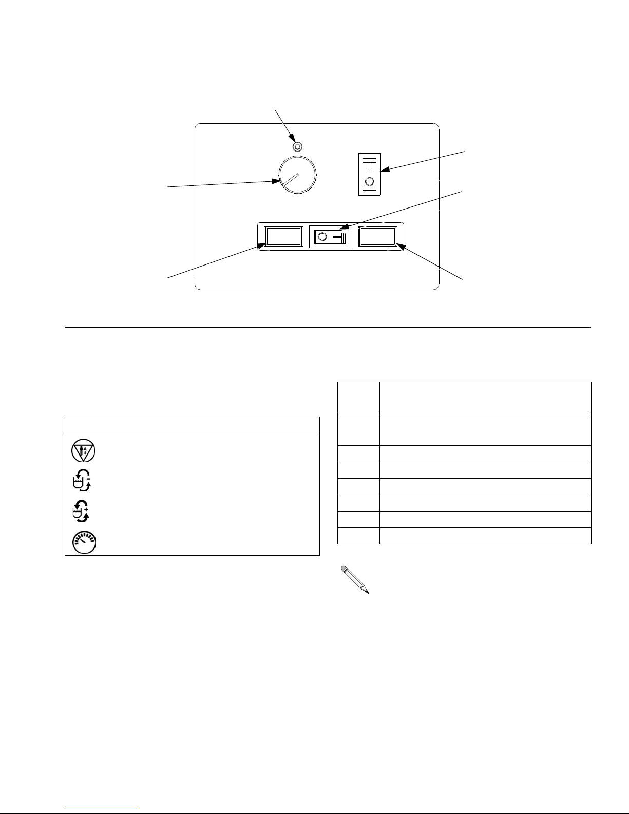
The EnergyComplete Sprayer has two recirculation
speeds, slow and fast, and an adjustable pressure out-
put.
Slow Recirculation
• Slow circulation results in a higher temperature
transfer in the heater, so hoses and gun heat up
quicker.
• Good for touchup or low flow spraying, up to moder-
ate temperature.
• Not used to circulate full pails up to temperature.
Fast Recirculation
• Use to support higher flow rates or higher tempera-
tures by preheating the pails.
• Agitates fluid within pails, to avoid heating only the
fluid at the top of the pail.
• Use for flushing.
Pressure Adjust
Automatically maintains selected pressure output for
dispensing or spraying.
Keep Components A and
B Separate
Compatible Solvents
Use the following solvents for cleaning and flushing A
and B fluid.
EnergyComplete Air
Infiltration Barrier
Temperature
Requirements
Material Storage
EnergyComplete Air Infiltration Barrier A and B fluid
should always be stored between 40-110°F
(4.4-43.3°C). The A side fluid (white) will freeze below
32°F (0°C).
If the A side fluid freezes, stir until the temperature is
between 40-110°F (4.4-43.3°C).
Application
Ensure the temperature of the EnergyComplete Air
Infiltration Barrier A and B fluid is between 70-110°F
(4.4-43.3°C).
Note: Use EnergyComplete pail insulators when spray-
ing below 40°F (4.4°C).
Post Application
Ensure that the ambient air temperature where Energy-
Complete Air Infiltration Barrier has been sprayed
remains above 20°F (-6.66°C) for 1 hour after spraying.
Lower temperatures and higher humidities slow the cur-
ing process. The foam will not be resilient until it cures.
The foam will fully cure once warmer temperatures and
lower humidity levels return.
CAUTION
To prevent cross-contamination of the equipment’s
wetted parts, never interchange component A (white
fluid) and component B (red fluid) parts.
A and B Fluid Compatible Solvent
A side (white) Water
B side (red) Owens Corning B-Side Cleaner

ComponentIdentification
8313221M
Component Identification
Key for FIG. 1
APumpA
BPumpB
CHeaterA
DHeaterB
E Compressor (not supplied with all units)
FCrossbar
G Pail Mounting Bracket
H Fluid Pressure Gauges
J Recirc/Spray and Overpressure Relief Valves
K Control Panel; see FIG. 2, page 9
L Electric Motor and Drive Housings
M Suction Tubes
N Recirculation Tubes
P Air Line outlet
R Outlet Hose Connections
S Recirculation Tube Connections
T Fluid Temperature Sensors
U Air Filter/Moisture Separator (behind bracket)
V Insulated Hose Bundle
WEnergyComplete Spray Gun
FIG. 1: Component Identification, Heated EnergyComplete Sprayer
C
D
K
L
E
T
F
M
N
UP
A
B
G
J
H
H
S
S
R
Heated Package 257126
r_256765_313221_b_2
V
W

Controls and Indicators
313221M 9
Controls and Indicators
Motor/Pump Control Function
Knob
Use knob (CF) to select desired function.
STATUS Indicator
• Indicator (ST) steady on: Motor Power switch is
turned on and control board is working.
• Indicator (ST) blinking: If error occurs, STATUS indi-
cator will blink 1 to 7 times to indicate status code,
pause, then repeat. See TABLE 1 for a brief descrip-
tion of status codes. For more detailed information
and corrective action, see page 25.
Motor Power Switch/Circuit
Breaker
Switch (MP) turns power on to control board and func-
tion knob. The switch includes a 20 A circuit breaker.
FIG. 2. Controls and Indicators
MP
CF
ST
HP
TD TD
r_256765_313221_b_37
Icon Setting Function
Stop/Park Stops motor and automati-
cally parks pumps.
Slow Recirc Slow recirculation speed.
Fast Recirc Fast recirculation speed.
Pressure
Adjust
Adjusts fluid pressure to
gun in spray mode.
Table 1: Status Codes
(see also the label on back of the control enclosure)
Code
No. Code Name
1 Pressure imbalance between A and B
sides
2 Unable to maintain pressure setpoint
3 Pressure transducer A failure
4 Pressure transducer B failure
5 Excessive current draw
6 High motor temperature
7 No cycle counter switch input
The default is to shut down if a status code indi-
cation occurs. Codes 1 and 2 may be set to dis-
able automatic shutdown if desired; see page
26. The other codes are not settable.

Controls and Indicators
10 313221M
Heater Power Switch/Circuit
Breaker
See FIG. 2. Switch (HP) turns power on to heater ther-
mostats. The switch includes a 20 A circuit breaker.
Heater Temperature Controls
See FIG. 3. Control knobs (HC) set temperature of com-
ponent A and B heaters. Indicator lights (HL) turn on
when thermostats are heating, and off when heater
reaches setpoint.
Fluid Temperature Sensors and
Displays
See FIG. 2. Fluid temperature sensors (T) monitor actual
temperature of component A and B fluid going to spray
gun. Temperatures are then displayed (TD).
Unit is shipped set to °F. To change to °C, see page 36.
FIG. 3. Heater Temperature Controls
HC
HC
HL
HL
C
D
T
T
MP
HP
r_256765_313221_b_16

Controls and Indicators
313221M 11
Air Compressor Power
Switch/Circuit Breaker
Switch (CP) turns power on to compressor and regula-
tor. The switch includes a 20 A circuit breaker.
Air Compressor Controls
Pressure Gauge (PG) indicates set air pressure by reg-
ulator.
Regulator (AR) sets desired air pressure.
FIG. 4
AR
PG
CP
r_256765_313221_b_2

Setup
12 313221M
Setup
Locate EnergyComplete Sprayer on a level surface. Do
not expose EnergyComplete Sprayer to rain.
Connect EnergyComplete Sprayer to the correct power
source for your model. See TABLE 2. Models with two or
three power cords must be connected to separate, dedi-
cated circuits. See FIG. 5.
The equipment must be grounded. Grounding reduces
the risk of static and electric shock by providing an
escape wire for the electrical current due to static build
up or in the event of a short circuit.
•EnergyComplete Sprayer: grounded through power
cord.
•Generator (if used): follow your local code. Start and
stop generator with power cord(s) disconnected.
•Spray gun: grounded through the supplied fluid
hoses, connected to a properly grounded Energy-
Complete Sprayer. Do not operate without at least
one grounded fluid hose.
•Object being sprayed: follow your local code.
•Solvent pails used when flushing: follow your local
code. Use only metal pails, which are conductive,
placed on a grounded surface. Do not place pail on
a nonconductive surface, such as paper, plastic, or
cardboard, which interrupts grounding continuity.
•To maintain grounding continuity when flushing or
relieving pressure, hold a metal part of spray gun
firmly to the side of a grounded metal pail, then trig-
ger gun.
1. Locate EnergyComplete Sprayer
2. Electrical Requirements
Improper wiring may cause electric shock or other
serious injury if work is not performed properly. Have
a qualified electrician perform any electrical work. Be
sure your installation complies with all National, State
and Local safety and fire codes.
3. Grounding

Setup
313221M 13
Table 2: Electrical Requirements
Model Required Power Source Power Cord Connector
256765 - 120 V, 1 phase, 50/60 Hz,
three 15 ft (4.5 m) power cords,
Heated
Three separate, dedicated circuits
rated at minimum of 15 A each
257089 - 120 V, 1 phase, 50/60 Hz,
two 15 ft (4.5 m) power cord, Heated
Two separate, dedicated circuits
rated at minimum of 15 A each
Three NEMA 5-15T
Two NEMA 5-15T
Table 3: Extension Cord Requirements
Required Wire Size
Up to 100 ft (30 m)
AWG 12
Cords must be 3-conductor grounded, rated
for your environment.
FIG. 5. Use Three Separate Circuits
1
Ensure no other high amp loads are connected
while running EnergyComplete Sprayer.
To verify separate circuits, plug in
EnergyComplete Sprayer or a worklight and
cycle breakers on and off.
1
2
To avoid electric shock, always unplug all cords before ser-
vicing EnergyComplete Sprayer.
Heater Power
Motor Power TI12383a
2
Compressor Power

Setup
14 313221M
Connect fluid supply hose to outlet hose connections (R,
FIG. 6). Fittings are sized to prevent connection errors.
Connect whip hose to fluid supply hose with adapter
(50) and nipple (51). Connect other end of hoses to A
and B inputs of gun.
Connect gun air hose to the gun air input and to the air
filter outlet (Z). If you are using more than one hose bun-
dle, join the air hoses with the nipple (305) provided with
the hose bundle.
On heated units with Fusion guns, connect the supplied
ball valve and quick-disconnect coupler to the gun air
hose, then connect the coupler to the gun air fitting.
For sprayers without a compressor, connect the main air
supply to the quick disconnect fitting on the air filter
behind the front brace. Air supply hose must be at least
5/16 in. (8 mm) ID up to 50 ft (15 m) or 3/8 in. (10 mm)
ID up to 100 ft (30 m).
Turn on air compressor power. Set regulator to desired
output pressure as indicated on the gauge.
The EnergyComplete Sprayer is tested with a plasti-
cizer oil at the factory. Flush out the oil with a compatible
solvent before spraying. See page 23.
4. Connect Fluid Hoses
5. Connect Gun Air Hose
6. Connect main air supply
7. Turn on Air Compressor
Air Filter/Moisture Separator (Z) is equipped
with an automatic moisture drain.
8. Flush Before First Use
FIG. 6. Hose Connections
R
Z
r_256765_313221_b_4

Setup
313221M 15
Keep the felt washers in the pump wet-cups saturated
with Graco ISO pump oil, Part No. 217374. The lubricant
creates a barrier between the red fluid and the atmo-
sphere.
9. Fill Wet-Cups
10. Install suction tube
NOTICE
To prevent cross-contamination of fluids and equip-
ment parts, never interchange component A and
component B parts or containers.
Label one pail “A” and the other “B”, using the labels
provided. Always doublecheck which material you
have before placing suction tubes in pails.
Using a drill and mixing blade, mix filled or sep-
arated materials in the pail. Material left in the
pails overnight may need to be remixed.
Fill wet-cups through
slots in plate, or loosen
screws and swing plate
aside.
Pump rod and connecting rod move during opera-
tion. Moving parts can cause serious injury such as
pinching or amputation. Keep hands and fingers
away from wet-cup during operation. Shut off Motor
Power before filling wet-cup.
a. Open red and white fluid pails and posi-
tion in front of suction tubes.
b. Stand behind unit and hold crossbar.
Lean unit backwards until the suction
tubes are above the supply pails.
c. Place suction tubes in pails.
Cut portion of the pail’s lid for suction tube and
assemble on pail to prevent debris from entering
pumps.
A
B
r_256765_313221_b_12
A
B
r_256765_313221_b_17

Setup
16 313221M
11. Mount pails
a. Insert pail handles on mounting bracket
(G).
12. Purge air and flush fluid from lines
a. Remove both recirculation tubes (N)
from the pails and secure each one in a
dedicated waste container (W).
b. Set function knob to Stop/Park .
c. Plug in power cord(s). See TABLE 2,
page 13.
A
B
G
r_256765_313221_b_18
N
A
BWr_256765_313221_b_19
d. Turn on Motor Power.
e. Set Recirc/Spray valves to Recirc.
f. Set function knob to Slow Recirc or
Fast Recirc .
g. When clean fluids exit both recirculation
tubes (P), set function knob to
Stop/Park .
h. Replace recirculation tubes in pails.
Preheat hoses if ambient temperature is
below 70°F (43.3°C) or continue with Startup,
page 18.
OR

Setup
313221M 17
Preheat Hoses
The ambient temperature must be greater than 40°F
(4.4°C).
If the ambient temperature is below 70°F(43.3°C) it is
required to preheat the hoses.
Connect circulation lines (CL) to circulation manifold
(701). Route circulation lines (CL) back to red and white
fluid pails.
1. Remove block (702). Install circulation manifold
(701) on gun fluid manifold (GM). Open all
valves in the fluid circuit.
2. Perform Startup, page 18.
3. Close fluid valves A and B. Remove circulation
manifold (701) from gun fluid manifold (GM).
Attach block (702) to circulation manifold to pre-
vent air from reacting with EnergyComplete Air
Infiltration Barrier.
TI4063a
B
A
GM
701
702
CL CL

Startup
18 313221M
Startup
Equipment surfaces can become very hot. To avoid
severe burns:
• Do not operate EnergyComplete Sprayer without
all covers and shrouds in place.
• Do not touch hot fluid or equipment.
• Allow equipment to cool completely before touch-
ing it.
• Wear gloves if fluid temperature exceeds 110°F
(43°C).
1. Perform Setup, pages 12-16.
2. Set function knob to Slow Recirc or Fast
Recirc .
3. Turn on Heater Power.
4. Temporarily set heater control knobs to maxi-
mum setting.
5. Circulate through heaters until temperature
readouts display desired temperature.
6. Adjust heater control knobs as necessary for a
stable spray temperature.
OR

Spraying/Dispensing
313221M 19
Spraying/Dispensing
Air is supplied to spray gun with gun piston
safety lock and gun fluid manifold valves A
and B closed (if present).
1. Set function knob to Stop/Park .
2. Set Recirc/Spray valves to Spray.
3. Turn function knob to Pressure Adjust .
Keep turning to the right until fluid pressure
gauges show desired pressure.
4. Check fluid pressure gauges to ensure proper
pressure balance. If imbalanced, reduce pres-
sure of higher component by slightly turning
Recirc/Spray valve for that component toward
Recirc, until gauges show balanced pressures.
The pressure imbalance alarm (Status Code 1)
is inactive for 10 sec after entering spray pres-
sure mode, to allow time to balance pressures.
Watch gauges for 10 sec to be sure pressure
holds on both sides and pumps are not mov-
ing.
5. Open gun fluid manifold valves A and B
(impingement mix guns only).
On impingement guns, never open fluid mani-
fold valves or trigger gun if pressures are
imbalanced.
6. Disengage piston safety lock.
7. Test spray onto cardboard or plastic sheet. Ver-
ify that material fully cures in the required length
of time, and is the correct color. Adjust pressure
and temperature to get desired results. Equip-
ment is ready to spray.
I
n t
hi
s examp
l
e,
B
s
id
e
pressure is higher, so
use the B side valve to
balance pressures.

Pause
20 313221M
Pause
To bring the hose and gun back to spray tem-
perature after a brief break, use the following
procedure.
1. Engage piston safety lock.
2. Set function knob to Slow Recirc .
3. Set Recirc/Spray valves to Recirc until tempera-
ture readouts come back up.
4. If you stop spraying for more than 2 minutes
when using an impingement mix gun, close gun
fluid valves A and B. Doing this will keep the
internal parts of the gun cleaner and prevent
crossover.
This manual suits for next models
2
Table of contents
Other Owens Corning Paint Sprayer manuals
Popular Paint Sprayer manuals by other brands

Gardena
Gardena 1L EasyPump Operator's manual

Central Pneumatic
Central Pneumatic 60314 Owner's manual & safety instructions

L-TEC
L-TEC IONSTAR 14882 user manual

sunjoe
sunjoe SPX-FC26 ASSEMBLY QUICK GUIDE

Enduraplas
Enduraplas ICEMASTER LIQUID MASTER T Series owner's manual

Master MFG
Master MFG SSBK-240 Assembly

Valex
Valex KOS12 Operating and safety instructions

MM
MM FR25 Use and maintenance manual

Fisher
Fisher SS-120 Owner's manual and installation instructions

Parkside
Parkside PFS 100 B2 Operation and safety notes

Workhorse
Workhorse LG05SSG2 Assembly / operation instructions / parts

Fimco
Fimco UTL-40-12V owner's manual