Print Your Plane As Many As You Like
Pre-Assembly Processes
OWLplane.com
Page : 2
Table of Content
Pre-Assembly Processes...............................................................................................3
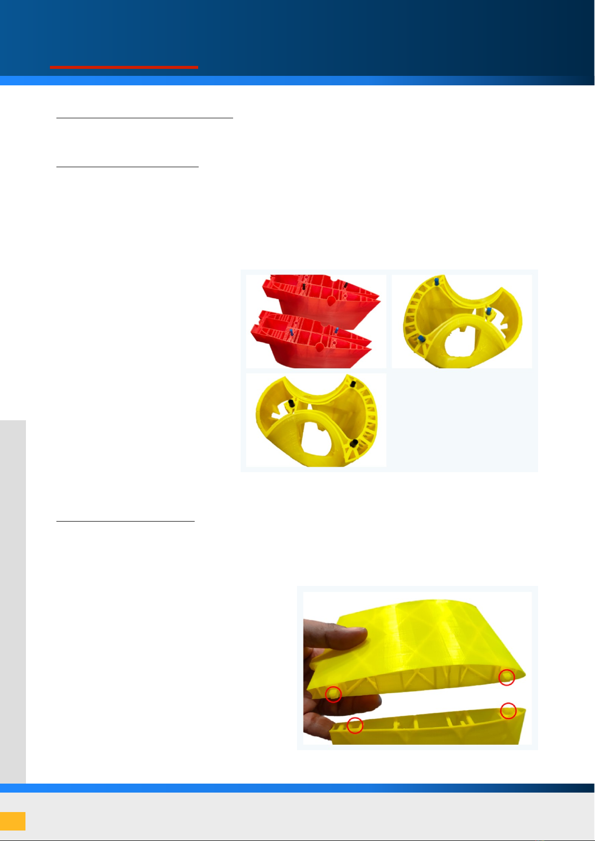
Tools Used for Cleaning and Clearing Tolerance
Cleaning and Clearing Tolerance
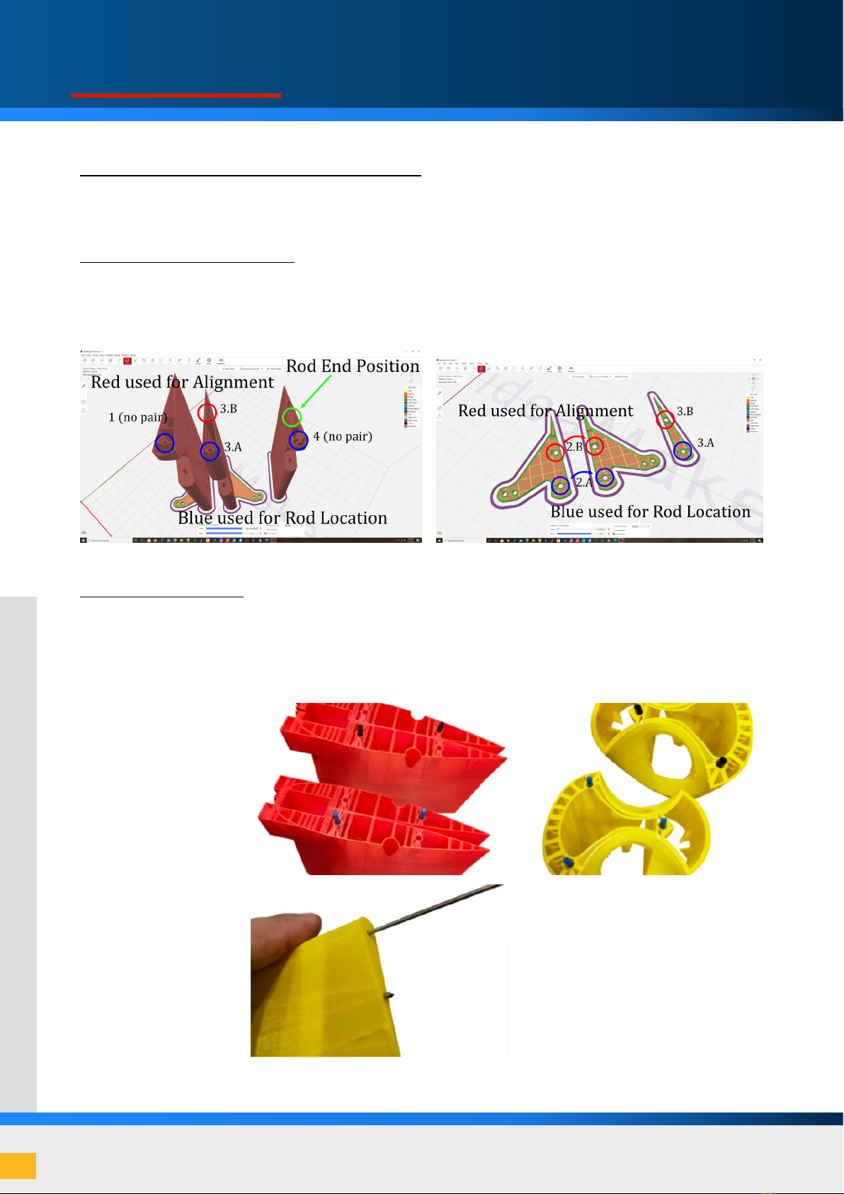
Finding and Checking Pin Position
Fuselage And Wing Assembly .....................................................................................8
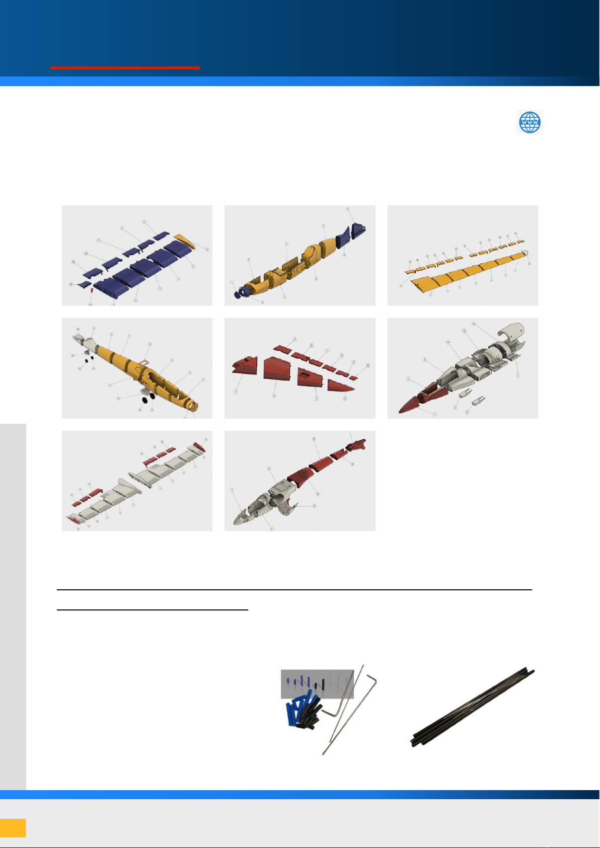
Preparing Required Hardware (Fiber Carbon Pin/3D Printed Plastic Pin and Fiber Carbon Spar)
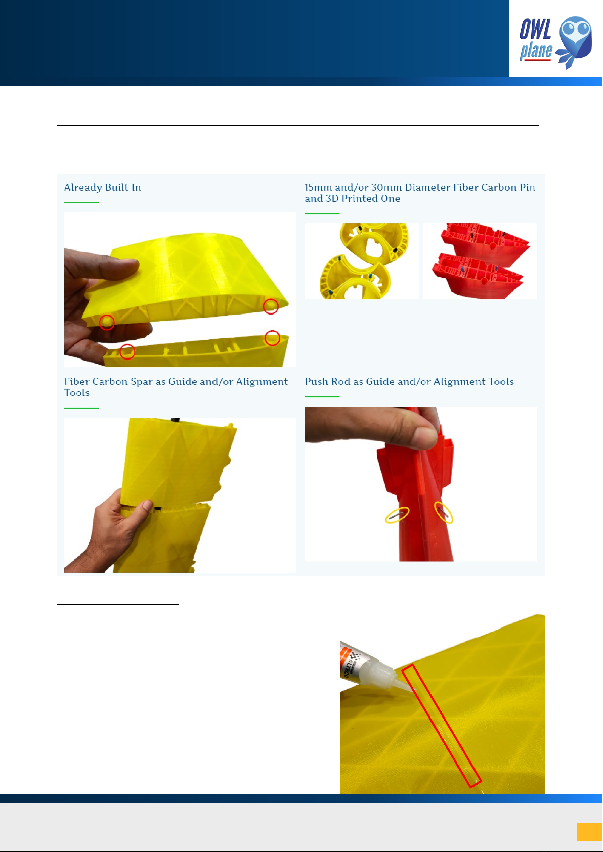
Guide and/or Alignment Tools or Mechanism for Fuselage and Wing
Gluing Two Parts
Wing And Fuselage Pin...............................................................................................10
3D Printed Plastic Pin
Screw, Nut and Washer
Stabilizer And Control Surface Assembly ...............................................................12
Preparing Pin and Rods
Guide and Alignment Tools and Mechanism
Gluing Two Parts
Canopy And Hatch Assembly ....................................................................................16
Parts, Spring and Pin
Inserting Spring and Latch
Gluing Printed Parts
Gears And Wheels Assembly .....................................................................................18
Preparing Gears and Wheels
Assembling Gears and Wheels
Placing and Locking The Battery..............................................................................20
Using Velcro Hooks and Loops
Plastic Holder for Double-Sided Hook and Loop
Servo Assembly ...........................................................................................................22
Preparing Pushrod and Parts
Installing and Assembling Servo and Push Rod using Servo Cover
Installing and Assembling Servo and Push Rod using Servo Bridge
EDF And Motor Mounting..........................................................................................26
Installing Outrunner Motor
Installing EDF Motor