Owlstone Lonestar Instruction Manual

OWL- LNS installation-90-0045-002 22/06/2011
© 2011 Owlstone Ltd Proprietary and Confidential Page 1 of 13
Quickstart Installation Guide for
Lonestar and At-Line Sampling Module

OWL- LNS installation-90-0045-002 22/06/2011
© 2011 Owlstone Ltd Proprietary and Confidential Page 2 of 13
Contents
NOTICES..............................................................2
OVERVIEW ..........................................................4
SOURCES OF FURTHER INFORMATION .........4
TOOLS REQUIRED............................................. 4
INSTALLATION................................................... 5
Notices
1.1 Contacting Owlstone
Visit the Owlstone website (www.owlstonenanotech.com) for up to date contact details and
service support:
For general inquires please email info@owlstonenanotech.com
U Office:
127 Cambridge Science Park
Milton Road
Cambridge
CB4 0GD
Tel: +44(0)1223 428200
Fax: +44(0)1223 428201
US Office:
400 Rella Boulevard
Suite 160
Suffern
NY 10901
Tel: +1 845 533 4225
Fax: +1 845 533 4232
1.2 Harmful substances
The LONESTAR and AT-LINE SAMPLING MODULE system can be used with a
wide range of samples, some of which could be toxic or harmful. On heating
these materials, flammable or toxic gases may be released.
The LONESTAR and AT-LINE SAMPLING MODULE system is not a fully sealed
unit, therefore for this reason it is essential that the user conduct a risk
assessment for the substances to be used in the LONESTAR and AT-LINE
SAMPLING MODULE and establish safety protocols to cope with the release of
such materials under the normal operation of the unit.
These protocols must include suitable installation (e.g. in a fume cupboard,
provision of extraction, etc.) and operational procedures to protect the
operator.
Materials with a fire point in excess of 183 °C must not be used in the AT-LINE
SAMPLING MODULE.

OWL- LNS installation-90-0045-002 22/06/2011
© 2011 Owlstone Ltd Proprietary and Confidential Page 3 of 13
Check chemical compatibility: Materials in the flow path include PTFE, stainless steel, aluminium,
silicon, graphite, circuit board and Viton®. Ensure test atmospheres are neither corrosive nor
reactive with materials in the flow path. If in doubt please contact an OWLSTONE representative
using the contact details provided.
1.3 Installation and Location
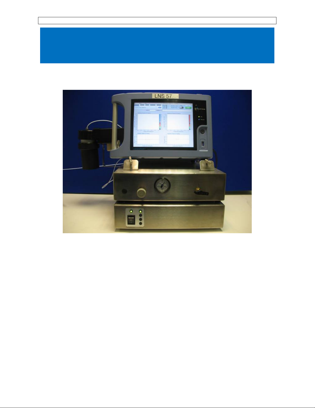
The LONESTAR and AT-LINE SAMPLING MODULE system together, unpackaged,
weighs ~20 kg; please take care in handling to avoid injury.
Before using the system, ensure that all power cables are intact with no
damaged insulation or frays.
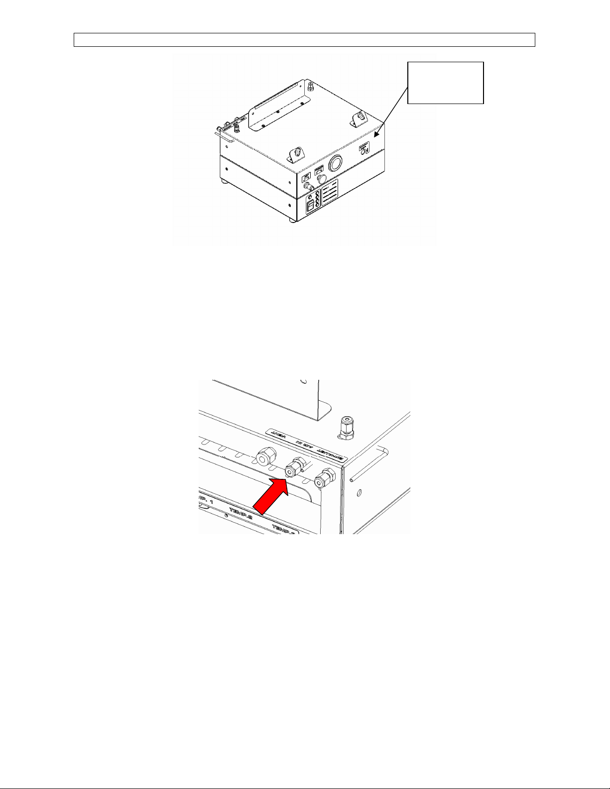
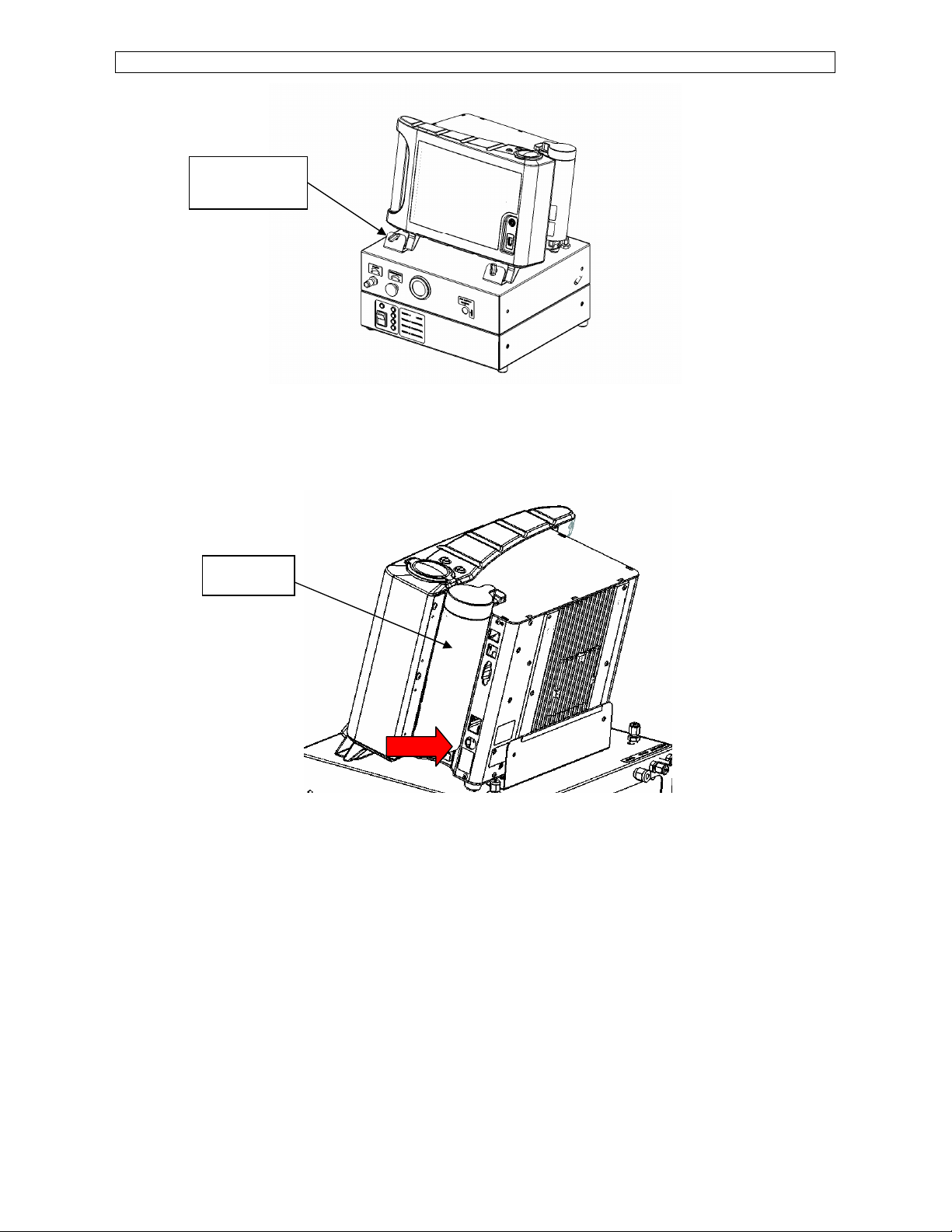
•Ensure that the LONESTAR instrument and AT-LINE SAMPLING MODULE are placed on a
solid, level surface, which is able to support their weight
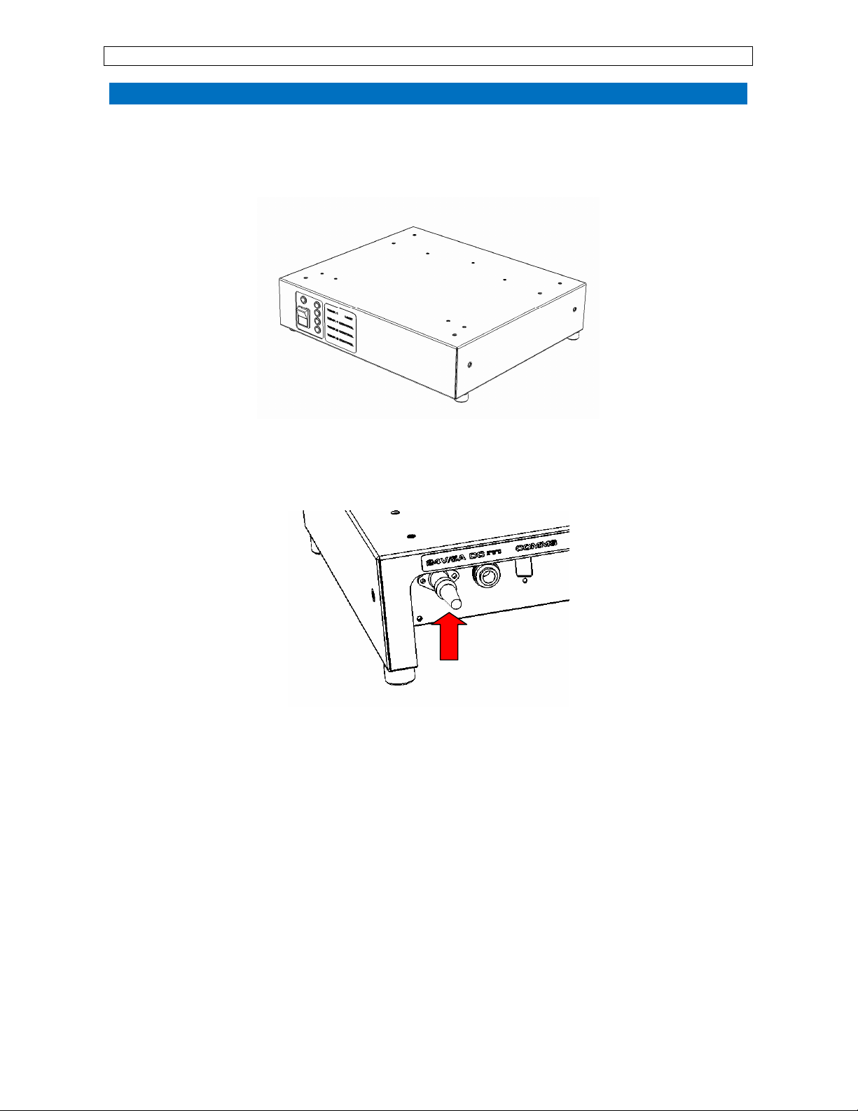
•Only use the OWLSTONE supplied power supply
•Ensure cabling is routed behind the system, at bench level, posing no risk of tripping.
Ensure all cables are detached from the LONESTAR instrument before attempting to move
the unit
•The LONESTAR instrument gets warm during operation. Handle with care and ensure there
is adequate ventilation around the system
•Do not place in space that is poorly ventilated or confined. Allow at least 50cm clearance
from walls and free flow of air around the system
•Do not place near flammable materials

OWL- LNS installation-90-0045-002 22/06/2011
© 2011 Owlstone Ltd Proprietary and Confidential Page 4 of 13
Overview
This document is a quick guide to help with installation of the Lonestar portable gas analyzer and
the At-Line Sampling Module attachment to it.
This document is only a supplement to the Lonestar User Manual and the At-Line Sampling
Module. These documents must both be read before starting to set up the instrument.
Sources of Further Information
More information is available in the following documents:
•The Lonestar System User Manual
•The At-Line Sampling Module Manual
•Lonestar Information: Troubleshooting Contamination of Lonestar Systems
•Installing and Using the Purge Automation Script
The above documents and more are available on the Owlstone customer support website:
http://owlstone.zendesk.com/home
For help with any further questions or problems, please contact Owlstone directly on our support
address:
[email protected]esk.com
Tools required
•7/16” spanner
•9/16” spanner
•3 mm Allen key

OWL- LNS installation-90-0045-002 22/06/2011
© 2011 Owlstone Ltd Proprietary and Confidential Page 5 of 13
Installation
1. Place the heater control box in the desired position. Be sure that it is placed on a solid,
level surface, which is able to support its weight, and has at least 50 cm clearance around
it. You will need to be able to access the back of the heater control box during the
installation.
Figure 1: Heater control box
2. Connect the power supply to the socket labelled ‘24V/5A DC’, at the back of the heater
control box.
Figure 2: Back of heater control box, showing power supply connection
3. Position the pneumatics box on top of the heater controller box.

OWL- LNS installation-90-0045-002 22/06/2011
© 2011 Owlstone Ltd Proprietary and Confidential Page 6 of 13
Figure 3: Pneumatics box on top of heater control box
4. Ensure that the air supply intended for the Lonestar system is clean (<0.1 ppm methane)
and dry (dew point <-45 °C). Ensure that the pressure at the outlet is not greater than 40
psi. Make sure that the switch on the front of the pneumatics box is set to the CLOSED
position.
5. Connect the dry air supply to the back of the pneumatics box using 1/8” Swagelok fittings.
Tighten with a spanner.
Figure 4: Dry air input to pneumatics box
6. Position the Lonestar on top of the pneumatics box and heater controller box. Make sure it
sits evenly with the feet and back edge of the instrument resting on the pneumatics box.
7. Adjust the screws on the footrests to gently hold the Lonestar in position.
Air
open/closed
switch

OWL- LNS installation-90-0045-002 22/06/2011
© 2011 Owlstone Ltd Proprietary and Confidential Page 7 of 13
Figure 5: Lonestar in position
8. Connect the Lonestar power supply to the socket on the side of the Lonestar, behind the
scrubber. The socket and plug each have a red mark on them and these should be lined up
before connecting them.
Figure 6: Side of Lonestar, showing power socket
9. Connect the Lonestar scrubber inlet to the outlet of the pneumatics box, using a short
length of 1/8” PTFE tubing and 1/8” Swagelok fittings. Tighten both connections with a
spanner.
Footrests with
screws
Scrubber

OWL- LNS installation-90-0045-002 22/06/2011
© 2011 Owlstone Ltd Proprietary and Confidential Page 8 of 13
Figure 7: Rear of Lonestar, showing scrubber inlet and pneumatics box outlet
10. Connect the exhaust outlet on the Lonestar to the exhaust inlet on the pneumatics box. As
before, use a short length of 1/8” PTFE tubing and 1/8” Swagelok fittings. Tighten both
connections with a spanner.
Figure 8: Left-hand side of Lonestar, showing Lonestar exhaust
and connection to pneumatics box
11. Next, connect the sampling module to the Lonestar by screwing the ¼” nut on the sampling
module to the ¼” fitting on the Lonestar. Tighten it with a spanner from above.
Scrubber inlet
Pneumatics
box outlet
Exhaust inlet
on pneumatics
box (top
surface)
Exhaust outlet
on Lonestar
(on right)

OWL- LNS installation-90-0045-002 22/06/2011
© 2011 Owlstone Ltd Proprietary and Confidential Page 9 of 13
Figure 9: Connecting the sampling module to the Lonestar
Figure 10: The nut connecting the sampling module to the Lonestar

OWL- LNS installation-90-0045-002 22/06/2011
© 2011 Owlstone Ltd Proprietary and Confidential Page 10 of 13
12. Screw the supporting strut to the side of the pneumatics box using the screw provided.
Figure 11: Attaching the support strut to the pneumatics box
13. Connect the clean air outlet on the Lonestar to the sample inlet on the sampling module
with a length of 1/8” PTFE tubing and 1/8” Swagelok fittings.
14. If your sampling module has been shipped with application-specific tubing and fittings for
the split and make-up ports, ensure these are connected according to the instructions
given by Owlstone’s technical staff. Otherwise, make sure the split and make-up ports are
capped off and covered by the black insulating caps.
15. Tighten all fittings with a spanner.
Figure 12: Sampling module inlet port (shown with insulating cap in place)

OWL- LNS installation-90-0045-002 22/06/2011
© 2011 Owlstone Ltd Proprietary and Confidential Page 11 of 13
Figure 13: Side of Lonestar showing clean air outlet
Figure 14: Rear of Lonestar and sampling module, showing
split and make-up ports (shown with insulating caps in place)
16. The sampling module has three heater plugs attached to it, labelled T1, T2 and T3. These
should be plugged in to the correct sockets at the back of the heater control box.
17. The communication cable should also be plugged in to the labelled socket at the back of
the heater control box. Plug the other end into one of the USB ports on the Lonestar.
(There are two at the side of the Lonestar behind the scrubber, and one at the front.)
Clean air
outlet on
Lonestar (on
left)
Split port
(higher)
Make-up port
(lower)

OWL- LNS installation-90-0045-002 22/06/2011
© 2011 Owlstone Ltd Proprietary and Confidential Page 12 of 13
Figure 15: Rear of heater control box, showing comms and heater sockets
Figure 16: Side of Lonestar, showing USB ports
18. Switch on the Lonestar using the switch next to the power socket. Then press the large
button on the front of the Lonestar to start it up. The Lonestar software should start
running automatically.
19. Turn the heater control box ON using the switch on its front. The four green LEDs should
light up.
20. Open the program ‘3-PID Configurator’, as described in the At-Line Sampling Module
Manual. Check that the three heaters on the sampling module are set to the correct
temperatures and heating up correctly.
21. Check that the pressure shown on the pneumatics box gauge is between 0.1 and 0.15 MPa
and turn the switch on the front to the OPEN position.
Comms cable
T1
T3
T2

OWL- LNS installation-90-0045-002 22/06/2011
© 2011 Owlstone Ltd Proprietary and Confidential Page 13 of 13
22. Adjust the dials on the front of the pneumatics box until the pressure and flow shown at
the top of the Lonestar software are the correct values for your application.
23. If Owlstone’s technical staff have not advised you of application-specific values for the
pressure and flow, set them to 1.0 bar
g
and 2.0 l/min.
Figure 17: Lonestar software dashboard, with gas pressure and flow display highlighted
24. When installed for the first time after shipping, the Lonestar must be cleaned down
overnight before use. To do this, take the following steps.
25. Select the ‘DF Matrix’ tab in the Lonestar software and press the green START button to
begin taking data. When prompted for a file name, enter the date and “Initial cleandown”.
26. Follow the instructions in the document ‘Installing and Using the Purge Automation Script’.
Turn on the script. This will ensure that all sections of the Lonestar’s internal flow path are
cleaned down.
Figure 18: Example DF matrices showing characteristic contamination from shipping
Figure 19: Example DF matrices after cleaning down
27. Once clean, the Lonestar and At-Line Sampling Module are ready to use.
This manual suits for next models
1
Table of contents
Popular Medical Equipment manuals by other brands

Defibtech
Defibtech Lifeline/ReviveR AUTO DDU-120 user manual

Physipro
Physipro Zero Pressure owner's manual

DentalEZ
DentalEZ Simplicity Installation, operation & care manual

BIO-MED DEVICES
BIO-MED DEVICES CROSSVENT-3+ Operation & service manual

lopital
lopital Amfora Instruction card

International Biophysics
International Biophysics AffloVest quick start guide