DentalEZ Simplicity User manual

®
Installation, Operation & Care Manual
®
Simplicity
Cart
Duo
Doctor’s

Simplicity®Cart
1
Table of Contents
Section I Introduction
Specications............................................................ 2
Classications........................................................... 2
ExplanationofSymbols&Signs............................ 3
Dimensions............................................................... 3
ExplanationofPackagingSymbols ....................... 4
Packaging ................................................................... 4
Section II Pre-installation
UtilityServiceCenter ............................................ 5
PlumbingContractor'sProcedure................... 5-6
ElectricalContractor'sProcedure ...................... 6
Section III Installation
USCBase .................................................................. 7
UmbilicalConnection............................................. 7
CartLeveling ............................................................ 8
CartLid ..................................................................... 8
Assistant'sAccessories........................................... 8
FiberOptics-Electrical(Optional) .................... 9
SyringeTubing........................................................... 9
ExplanationofControlSymbols.......................... 9
Section IV Testing
DeliverySystem.....................................................10
FootControl&Handpiece ...........................10-11
Syringe .....................................................................11
FiberOptics(Optional) .......................................11
Section V Operation
DeliverySystem.................................................... 12
Handpiece .............................................................. 13
Syringe .................................................................... 14
FootControl/Chipblower................................14
FiberOptics(Optional) ......................................14
CleanWaterSystem............................................ 14
Section VI Care
Cleaning.................................................................. 15
Disinfecting ............................................................ 15
Section VII User Service
Information
DeliveryHead....................................................... 16
Handpiece ........................................................17-18
ServiceInstruction............................................... 18
DisposalofEquipment ........................................18
Section VIII Parts List / Diagrams
UtilityServiceCenter ......................................... 19
DeliveryHead/CleanWaterSystem.............. 20
Manifold.................................................................. 21
ControlBlock ....................................................... 21
CartReplacementParts ..................................... 22
FootControl ......................................................... 22
Air/WaterSyringe.............................................. 23
HVENozzle........................................................... 23
SENozzle............................................................... 23
Limited Warranty ........................................... 24
EMC Information ......................................25-28
Tubing Diagram

Simplicity®Cart
2 Installation,OperationandCareManual
Section I Introduction
This manual contains installation, operation and care
instructions and user service information for the
Simplicity®Cart Delivery Unit.
The Simplicity Cart is available in two standard con-
gurations: (1) Duo (doctor's and assistant's) instru-
mentation and (2) doctor's only instrumentation.
The Simplicity Cart Delivery Unit is intended to be
used by trained professional dental care personnel
as an interface device to connect the dental oper-
atory hand instruments to the appropriate supply
utility such as air, water, vacuum, drain and electrical.
It functions as a system management device that
provides a method of operating the hand instruments
from a single control input device.
The Simplicity cart, situated on wheels, positions
the handpieces for the optimum presentation to the
operator.
The Unit is designed to provide trouble-free service
when installed, operated and maintained according to
the procedures set forth in this manual.
To ensure correct installation, carefully read all
the procedure instructions contained in this
manual paying close attention to all notices,
notes, cautions and warnings.
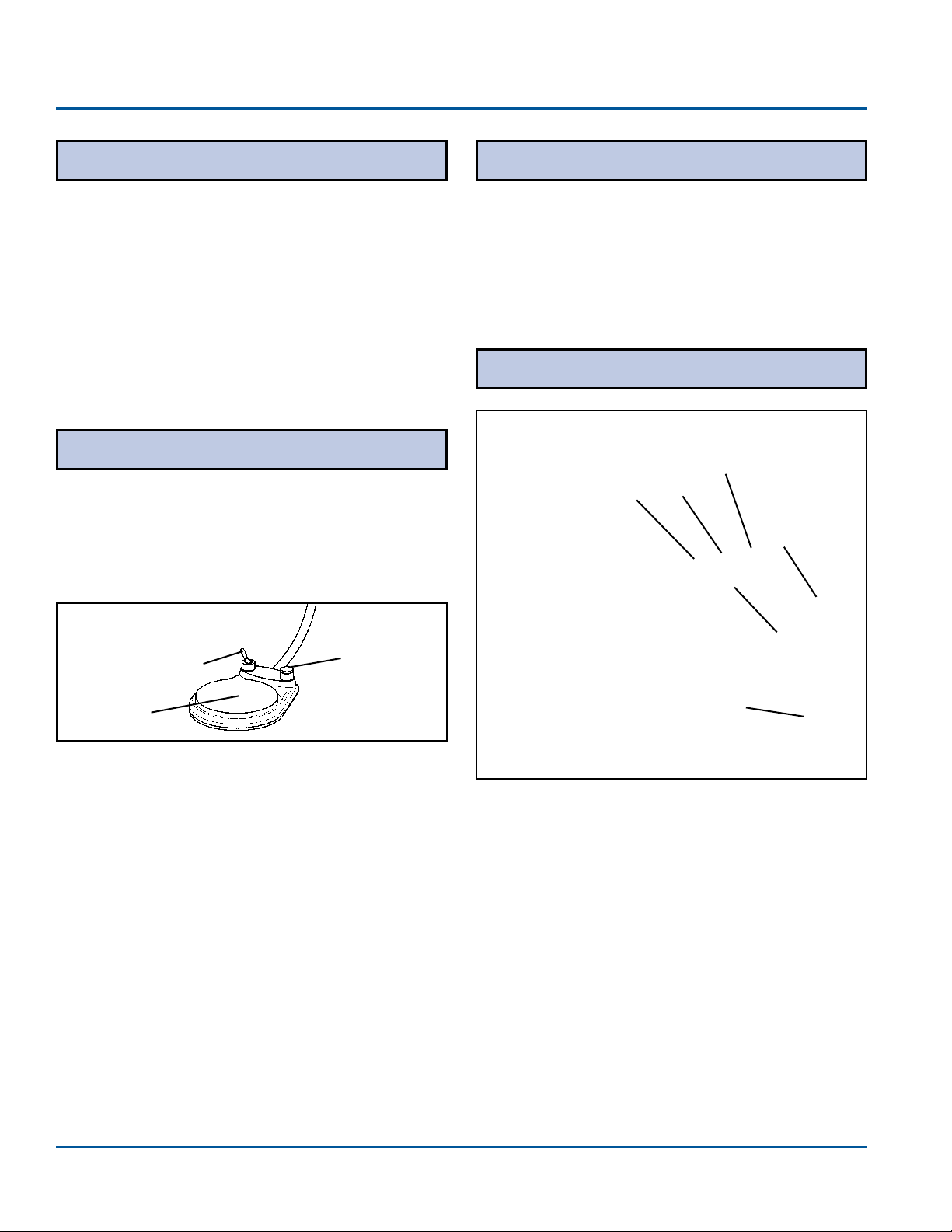
Before proceeding, please review the photo below to
become familiar with the basic components of the Unit.
After the Simplicity Cart is installed, please review
the operation procedures and care guidelines with the
doctor's staff. Then leave this manual in the doc-
tor's ofce for future reference.
Utility Service
Compartment
Clean
Water
System
Doctor's
Controls
BASIC COMPONENTS
Work
Surface
Specications
Power Supply - 100-240V, 50-60 Hz., as applicable
Air Pressure - 551.6 pKa (80 PSI)
(at regulator in USC)
Water Pressure - 275.8 pKa (40 PSI)
(at regulator in USC)
Clean Water System -
Reservoir Capacity - 1.5 L
CMU Shipping Weight
Cart with transformer - 61.2 kg (135 lbs.)
Cart without transformer - 47.6 kg (105 lbs.)
Maximum Load for Cart Top - 0.453 kg (10 lbs.)
Recommended Environmental Conditions
– Environmental conditions for transport and storage:
- Relative humidity range within 0% to 95%
- Transport/storage temp. within -29ºC (-20ºF) to
74ºC (165ºF)
– Environmental conditions for operation:
- Conditioned Air
-
Atmospheric pressure range within 500 to 1050 kPa
- Operation temp. within 15ºC (59ºF) to 27ºC (80ºF)
Air and Water Inlet Temperature Range:
5ºC (41ºF) to 27ºC (80ºF)
Medical-GeneralMedicalEquipment
Certiedastoelectricalshock,re
andmechanicalhazardsonlyin
accordancewithUL60601-1,
CAN/CSA-C22.2No.601.1,
CAN/CSA-C22.2No.60601-1(2008)&
ANSI/AAMIES60601-1(2005).
Classications
0459
53HN
– Type of protection against electric shock: Class 1
Equipment
– Degree of protection against electric shock: Type B
Applied Parts. The handpiece is considered an applied part.
– Degree of protection against the ingress of water:
Ordinary
–Equipment not suitable for use in the presence of a
ammable anesthetic mixture with air or with oxygen
or nitrous oxide.
– Mode of operation: Continuous
These specications apply to model SP-A (doctor's
only instrumentation) and model SP-B (doctor's and
assistant's instrumentation).
Temperatures not within the air and water inlet
termperature range could cause damage to the unit.
CAUTION
Simplicity®Cart
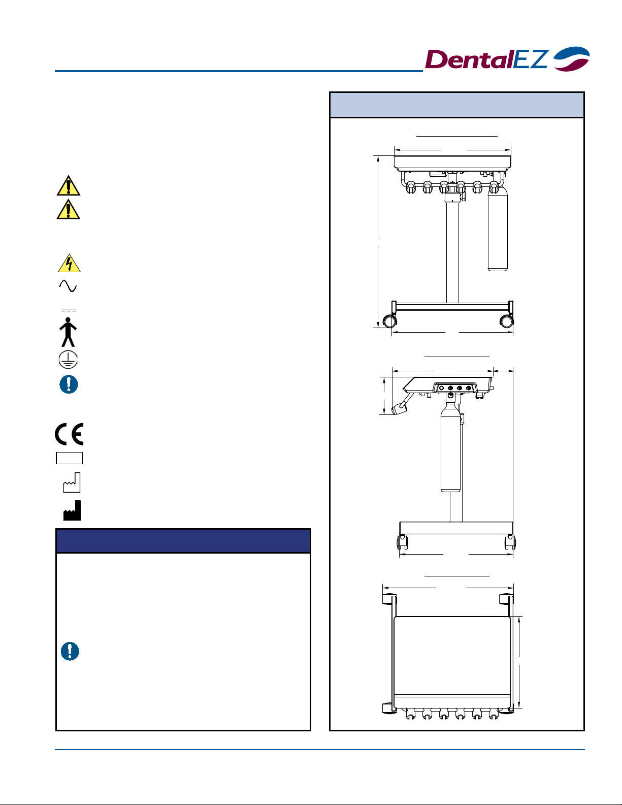
3
21-9/16"
14-7/8"
6-1/8"
16-5/8"
28"
19-1/4"
18-3/4"
3-5/16"
20"
Section I Introduction
Dimensions
UNIT FRONT
UNIT TOP
UNIT SIDE
TheauthorizedEuropeanrepresentativeis:
DentalEZ(GB)Ltd.,ClevelandWay
HemelHempstead,Hertfordshire,HP27DY,England
Phone:(01442)269301
Attn:Mr.JeffWhitehouse
=Caution
=Warning
=Biohazard
=WarningDangerousVoltage
=AlternatingCurrent
=DirectCurrent
=TypeBAppliedPart
=ProtectiveEarth(ground)
=GeneralMandatoryAction
=RefertoManual(followinstructions)
=EuropeanCertication
=SerialNumber
=ManufactureDate
=Manufacturer
Explanation of Symbols and Signs:
SN
●
In accordance with Part 15 of FCC rules, this
equipment was tested and complies with Class
A digital device limits. These limits are designed
to give equipment reasonable protection against
detrimental interference when operated in a
commercial environment.
●
Medical electrical equipment needs special
precautions regarding electromagnetic
compatibility (EMC) and needs to be installed
according to EMC information. (See EMC
Information, Pages 25 through 28.)
●
Mobile radio frequency (RF) communications
equipment can affect medical electrical
equipment.
NOTICE

Simplicity®Cart
4 Installation,OperationandCareManual
=BoxMustRemainUpright
=
DoNotPlaceBoxOnUnlevel
Surface
=DoNotStackBox
=
BoxContentsSafeTemperature
Range
=BoxContentsSafeHumidityRange
Packaging
The Simplicity Cart Delivery Unit components are
packaged and shipped according to the shipping con-
gurations on this page.
NOTE:
Be aware that some cartons are shipped with
packing inserts that may be empty (even if optional
components are ordered).
Please verify the Simplicity Cart components packag-
ing contents against the packing list.
Simplicity Cart Unit Carton Contents:
•Cart Assembly
• Utility Service Center (USC) Box
• High-volume Evacuator (HVE) & Saliva
Ejector (SE) Components (Duo only)
• Utility Components (if ordered)
• Literature Assembly
• Utility Supply Bag:
- Elbow Fitting
- Adaptor Fitting
- 90 Deg. Valves (2)
- Adaptors (2)
- Fitting Assembly
- #10 x 1/2 Screws (4)
- Actuator Valve Assembly
• Assistant's Arm Supply Bag (Duo only):
- HVE Aseptic Sterling Tubing
- SE Sterling Tubing
- HVE Handle Valve
- SE Handle Valve
- Disposable Solid Trap Pkg. Assembly
Section I Introduction
SHIPPING CONFIGURATION
Cart
Assembly
Option Box
Insert
Foot
Control Box
USC Box
Pallet
Installation by an authorized DentalEZ dealer service
technician is recommended.
NOTICE
Do not modify the Simplicity Cart without permission
from DentalEZ.
WARNING
For any questions about an order, please
contact a DentalEZ Equipment customer service
representative at 1-866-DTE-INFO.
NOTICE
Do not position equipment so that it is difcult to
unplug the unit from the power receptacle.
WARNING All parts supplied are necessary for proper installa-
tion, so be sure not to discard any hardware or com-
ponents until installation is complete.
-29ºC
(-20ºF)
74ºC
(165ºF)
0%
95%
-29ºC
(-20ºF)
74ºC
(165ºF)
0%
95%
-29ºC
(-20ºF)
74ºC
(165ºF)
0%
95%
-29ºC
(-20ºF)
74ºC
(165ºF)
0%
95%
-29ºC
(-20ºF)
74ºC
(165ºF)
0%
95%
Explanation of Packaging Symbols:
Simplicity®Cart
5
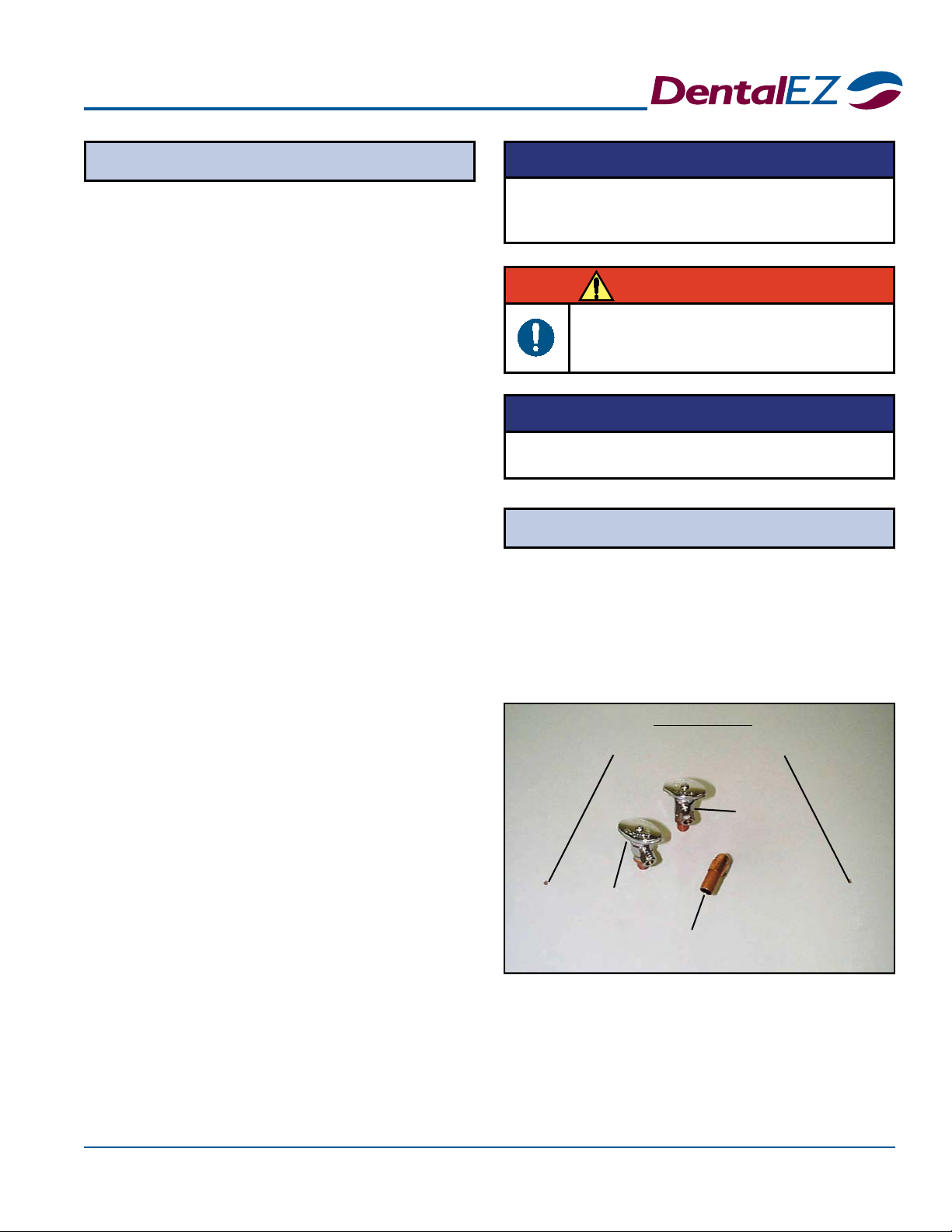
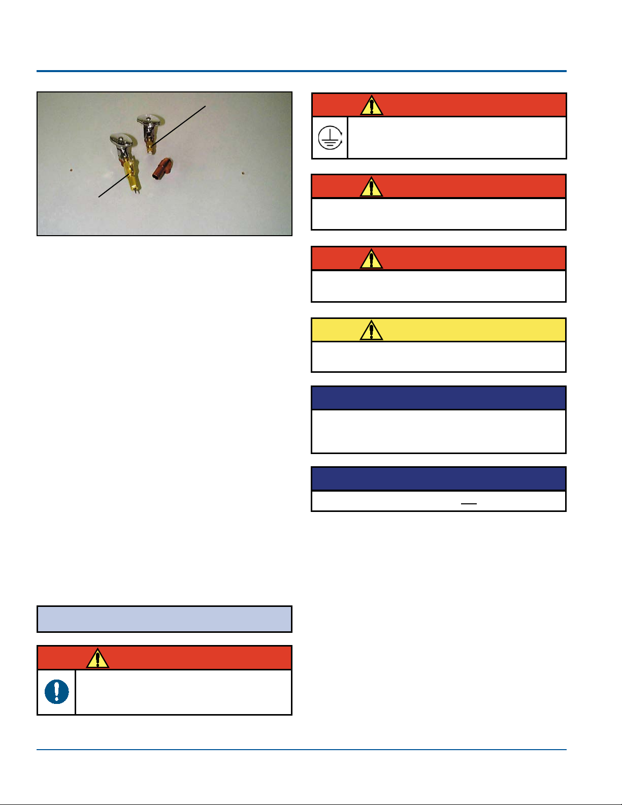
Section II Pre-installation
Utility Service Center
USC Carton Contents:
• Utility Service Center (USC)
•USC cover
• USC base (oor plate)
•USC Template
• Bag of supplies:
-Two #6 x 3/8" screws
-Four #10 screws
-Two adaptors
- Four plastic anchors
- 1/8" tubing barb
- Plug cap
- Two 1/8" tubing clamps
- Five 1/4" tubing clamps
-Elbow assembly
- Elbow tting
- Four 6-32 x 1/2" screws
- Four 6-32 nuts
- Pin housing, three position
- Two coupler ttings
- Air tting assembly
-Two stop valves
-Water actuator valve assembly
-Washer
NOTE: Set the USC cover aside until all installation
and testing is complete.
NOTE: For wood or metal oors, drill 5/32" holes.
For concrete, drill 1/4" holes and install plastic anchors.
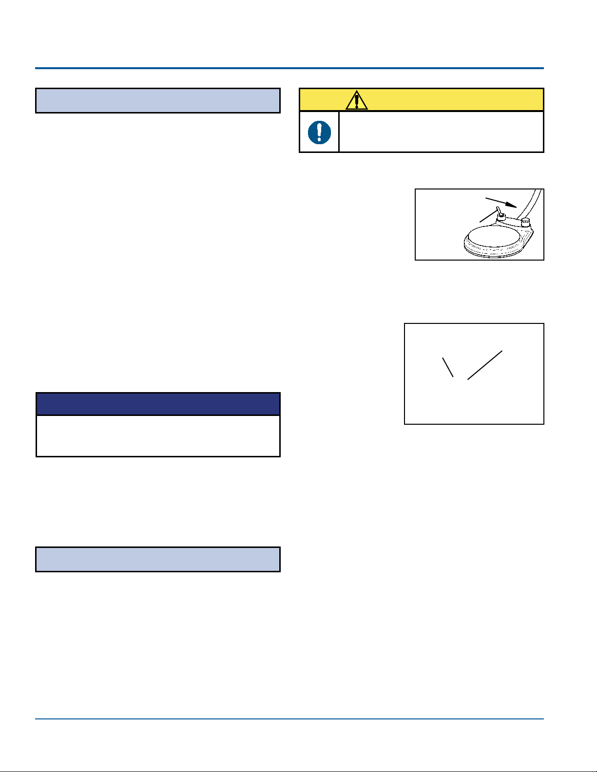
USC Base Mounting Holes
Air Stop
Valve
Water
Stop
Valve Vacuum
Elbow
WALL SIDE
Plumbing Contractor's Procedure
1. Remove the full-size USC template found in
the USC Carton.
2. Position the USC template according to the
exact layout indicated, making certain correct
distance from base to chair is maintained.
3. Using the USC template, drill two mounting
holes for the USC base. But do not secure the
base to the oor at this time.
(Typical Layout)
1. Open the USC bag of supplies.
2. Using the USC template, stub the utilities
through the oor and orient as shown in the
template. (Vacuum and drain ttings not supplied.
Refer to the USC template for requirements.)
Before proceeding with plumbing
installation, comply with and maintain all
applicable utility codes and regulations.
WARNING
DO NOT DISCARD the USC template after use.
Neatly refold it and place it in the back of this
manual.
NOTICE
For reference, a color-coded tubing diagram is
included with this manual.
NOTICE
Simplicity®Cart
6 Installation,OperationandCareManual
Section II Pre-installation
The electrical contractor is to provide a covered
115/220 VAC receptacle which meets all applicable
utility codes and regulations.
For the recommended location of the 115/220 VAC
receptacle, see the USC template.
NOTE: If the recommended location is not met, the
USC base may interfere with the 115/220 VAC
receptacle.
Air Fitting
Assembly
Water Actuator
Valve
Assembly
Electrical Contractor's Procedure
NOTE: Pay close attention to the orientation of the
template to the wall.
3. Sweat the valve adaptors to the air and water
stubs.
4. Apply the appropriate thread sealant to the
valve adaptors and install the stop valves.
5. Sweat the vacuum elbow to the stubs.
6. Sweat the hose connectors to the elbows
as applicable and orient as shown in the
template.
7. Flush the air and water lines to remove trash
and debris from the lines.
8. Connect the water actuator valve assembly to
the water stop valve as shown in the template.
Using a 5/8" open-end wrench, tighten the
nut securely.
9. Connect the air tting assembly to the air
stop valve as shown in the template. Using
a 5/8" open-end wrench, tighten the nut
securely.
(Typical Layout)
Before proceeding with electrical installation,
all wiring must be in accordance with NEC
and local electrical codes.
WARNING
Electrical contractor's parts are not supplied.
NOTICE
Rating of main circuit breakers should be 20 Amp
maximum.
CAUTION
WARNING
To avoid the risk of electrical shock, this
equipment must only be connected to a
supply mains with protective earth.
WARNING
Isolating the unit from the supply mains is
accomplished by unplugging the unit from the power
receptacle.
NOTICE
Do not connect items that are not part of the system
to the cart.
WARNING
Only use power supplies that are supplied by
DentalEZ as part of the Simplicity Cart.
Simplicity®Cart
7
Section III Installation
USC Base
Umbilical Connection
1. Position the USC base over the two mounting
holes that were drilled during pre-installation.
2. Secure the base using two #10 screws.
1. Attach the red incoming air pressure line to
the air tting assembly using the compression
tting supplied.
3. Trim the 5/8" vacuum line. Then install the
5/8" vacuum line on the vacuum elbow.
4. Slide a 1/8" tubing clamp onto the yellow
signal air line from the umbilical. Connect
this line to the water valve/actuator.
5. Open the air stop valve and check for leaks.
2. Slide a 1/4" tubing clamp onto the red air
line from the umbilical. Connect this line to
the remaining 1/4" barb on the air regulator
assembly.
5/8"
Vacuum
Line
Incoming Green Water Line
Green Line
Marked "W"
Water
Regulator
●
Before making tubing connections, use soap to
lubricate all in-line barbs and lines.
● After making each connection, secure by sliding
an appropriate size tubing clamp over the barb/
tube connection.
NOTICE
If the city water option was ordered, follow the
instructions included with the kit.
NOTICE
(Typical Layout)
Red Incoming Air
Pressure Line
Yellow
Signal
Air Line
Red Air Line from Umbilical
Water
Stop
Valve
Air
Stop
Valve
Water Valve/
Actuator
(Typical Layout)

Simplicity®Cart
8 Installation,OperationandCareManual
Section III Installation
Cart Leveling
1. Make sure the cart is on a level oor (Move the
cart to a level location if necessary.)
2.
Close the top cover of the cart. Then check the
side to side and front to back level of the top.
3. If leveling is necessary, loosen the four
mounting (3/8-16) screws and turn the
appropriate leveling set (1/4-20) screw.
4. When the top is level, re-tighten each mount-
ing screw.
Cart Lid
Saliva Ejector(SE)
1. Connect the SE
valve to the 5/16"
O.D. tubing.
Closed
1/2" Port
5/16" O.D.
SE Tubing
Connects
Here
Instrument
Holder
High-Volume Evacuator (HVE)
1. Connect the
HVE valve
to the 5/8"
O.D. tubing.
2. Hang the HVE valve in the instrument holder.
3.
Connect the tubing to an open 1/2" port under
the solids collector located under the cart.
4. If an optional second HVE valve is used, do
the following:
a. Insert a sharp, pointy object into the
closed 1/2" port under the solids
collector and create a smooth opening.
b. Repeat Steps 1 through 3.
Air / Water Syringe(Optional)
NOTE: Connections for the optional air / water
syringe are factory installed.
2. Hang the SE valve in the instrument holder.
3.
Connect the tubing to the open 1/4" port
under the solids collector in the assistant's arm.
Leveling
Set Screw
Mounting
Screw
Assistant's Accessories
1. To open the cart lid, unscrew the lid screw
located under the cart's chassis.
2. The lid is now free to open and close.
3. When the lid is closed, screw in the lid screw.
Lid
Screw
SE Valve
HVE Valve
5/16" O.D.
Tubing
5/8" O.D.
Tubing
5/8" O.D.
HVE
Tubing
Connects
Here
5/8"
Vacuum
Line
Connects
Here
Simplicity®Cart
9
Fiber Optics - Electrical(Optional)
Syringe Tubing
Section III Installation
1. Hang the syringe in the holder.
2. Connect the air and water lines to the
appropriate male and female connectors in the
delivery head chassis.
NOTE: If the optional ber optics were included in
the original order, electrical connections have been made
inside the delivery head at the factory. Plug the ber
optic transformer into the outlet and the harness from the
cart umbilical.
=ON(Power)
=Standby(Power)
=Water
=NoWater
=Flush
=ChipAir
=WaterBottle
=CityWater
=HandpieceDrive(Air)
=CoolantAir
=CoolantWater
=Variability
Explanation of Control Symbols:
Simplicity®Cart
10 Installation,OperationandCareManual
1. Pull the locking knob and turn the adjustment
knob on each regulator until the correct
pressure reading is reached.
2. When nished, push the locking knob down.
Section IV Testing
Coolant Water Lines
Utility Service Compartment
1. Turn on all services supplying the USC.
2. Open the air and water manual stop valves by
turning the knobs counterclockwise.
3. Inspect all joints and connections for leaks.
4. Plug the power cord from the ber optics into
an electrical outlet.
5. Turn the master switch ON.
6. Inspect for leaks in the service console and
delivery head.
Air and Water Filter/Regulators
If the regulators are not set at 551.6 pKa (80 PSI) for
air and 275.8 pKa (40 PSI) for water, do the following
adjustment process:
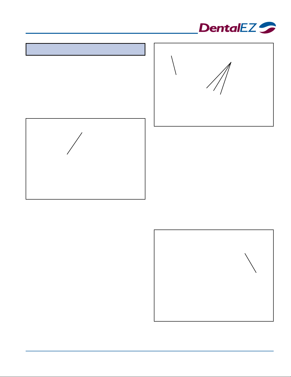
Delivery System
Foot Control & Handpiece
WET/DRY
Toggle Valve
Wet
1. At the foot
control, ip the
toggle valve to
WET.
2. Purge air from the coolant water lines for each
handpiece as follows:
a. Make sure master switch is in ON
position.
b. Open
the water
coolant
valve to
the full,
open
position.
c. Pick up a handpiece tubing and lay the
end into a sink or cuspidor bowl.
d. Simultaneously depress the foot control
disc and hold the ush valve, located in
the back of the delivery head, in the ush
position. Let water ow until all air has
escaped.
e. Return the handpiece tubing to its holder.
f. Repeat steps c. through e. for each
additional handpiece tubing.
Water
Coolant
Valve
Master
Switch
Chipblower
If the handpiece utilizes coolant air, a burst of air
should be delivered to the handpiece when the chip
air valve on the foot control is depressed.
Before utilizing handpieces, all air must be
purged from the coolant water lines to allow
the system to function properly.
CAUTION
The air regulator is factory preset to deliver 551.6
pKa (80 PSI). The water regulator is preset to deliver
275.8 pKa (40 PSI).
NOTICE
Simplicity®Cart
11
Section IV Testing
Air Pressure
1. Flip the toggle valve to DRY at the foot
control.
2. To adjust the individual handpiece drive air
pressure to the manufacturer's specications
do the following procedure:
a. Remove the handpiece from its holder.
b. Hold the handpiece, fully depress the
foot control and observe the amount of
air pressure delivered to the handpiece
indicated on the drive air pressure gauge
located on the side of the cart.
c. Locate the air pressure adjustment screws
on the bottom of the delivery head
chassis.
If the unit is equipped with a syringe, rst depress the
air button and then the water button to test the ow.
Syringe
Air Pressure
Adjustment
Screws
d. Turn the air pressure adjustment screw
on the control valve of the appropriate
handpiece (counterclockwise to increase
pressure, clockwise to decrease pressure) until
the handpiece manufacturer's correct
specication registers on the pressure
gauge.
3. Repeat a. through d. in Step 2 to set the
pressure for each handpiece.
NOTE: If a low-speed handpiece is required, slide the
pinch clamp over the appropriate water line going through
the pinch valve.
Follow the test procedures outlined in the instructions
included in each ber optic handpiece package.
Fiber Optics(Optional)
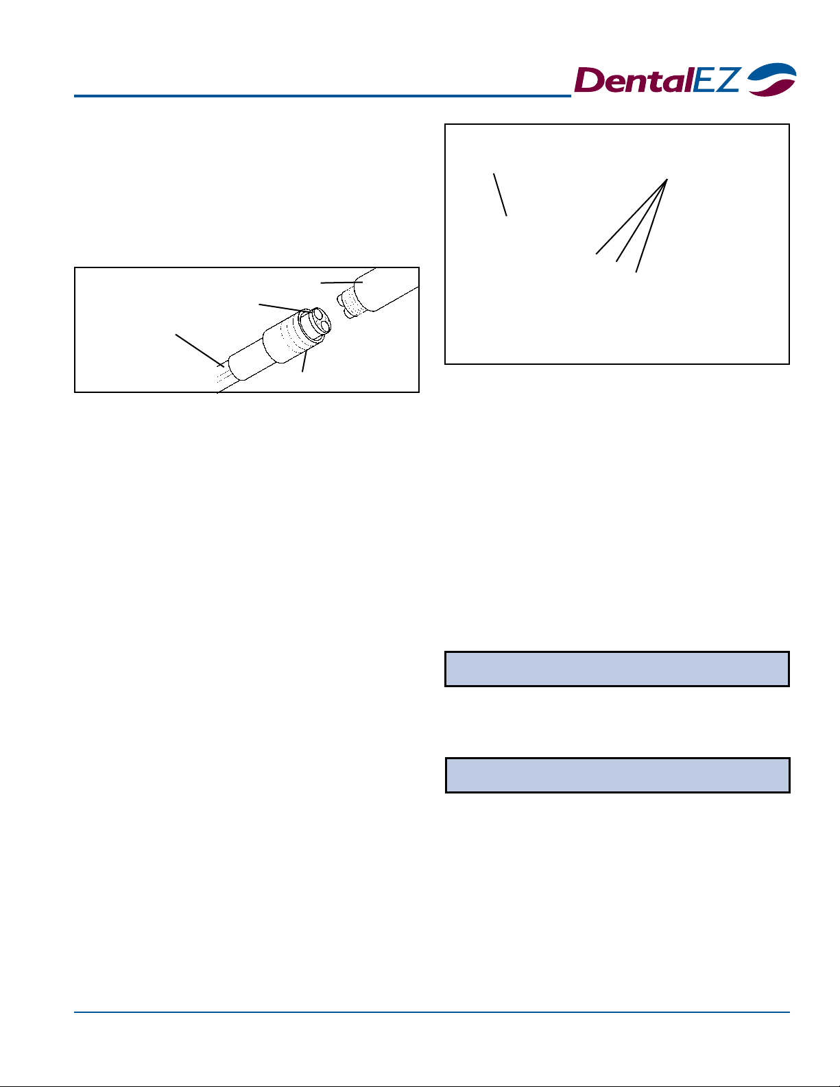
Tubing
Adaptor
Handpiece
Nut
Drive Air
Pressure
Gauge
3. Attach the handpiece to the tubing as follows:
a. Slide the connector nut down along the
tubing to expose the handpiece adaptor.
b. Carefully align and insert the handpiece
base into the adaptor. Then replace and
tighten the connector nut.

Simplicity®Cart
12 Installation,OperationandCareManual
Section V Operation
Instrument Hanger
•An automatic CUT OFF, can be demonstrated
by placing tubing in the hanger and disabling
operation for that position.
Some of the Simplicity Cart Delivery Unit design
features:
•Operation of three handpieces and a syringe.
•Drive air may be adjusted individually for each
handpiece.
•
An automatic cut-off valve in each handpiece
holder section disables operation for that position.
•
Foot control toggle valve allows wet or dry cutting.
•Master switch turns entire unit ON and OFF.
Delivery System
Master Switch
Oil Collector/
Filter Cover
Screws
• Each handpiece holder angle can be adjusted by
using an Allen wrench to loosen two set screws
in the back of each section and rotating it to the
desired angle; then re-tightening the screws.
• An oil collector/lter is designed to collect oil
from the handpiece exhaust air. Once a week,
check the lter for cleaning or replacement by
removing the two screws that secure the lter
cover.
Hanger
Bar
Handpiece
Holder Section
Automatic
Cut Off
Valve
Master Switch
The master switch controls the ON/OFF function
of air, water and electricity to the entire unit. Flip the
master switch to turn ON the unit.
Drive Air
Water Adjustment
Water Outlet
Air Outlet
VERY IMPORTANT: At the end of each work day
and anytime the unit is unattended, make sure the
master switch is in the OFF position.
CAUTION
To prevent possible injury because of accidental
operation, do not leave young children unattended.
WARNING
Simplicity®Cart
13
Section V Operation
Handpiece
Coolant Water Adjustment
•Coolant water spray to all the handpieces can
be turned ON or OFF using the toggle switch
located on the foot control.
• The coolant spray volume is regulated for each
handpiece by using the coolant water adjustment
valve located on the side of the delivery head.
• While operating a handpiece, turn the coolant
water adjustment valve counterclockwise (while
looking directly into valve) to increase the volume of
coolant water spray. To decrease volume, turn
the valve clockwise.
Air Pressure
Air pressure to each handpiece can be adjusted to
the manufacturer's specications by following the air
pressure instructions in Section IV Testing under the
heading Air Pressure on Page 11.
NOTE: These procedures must be done while:
•The master switch is in the ON position,
•The handpiece is out of its holder and
•The foot control is fully depressed.
NOTE: When making necessary air pressure
adjustments, refer to the air pressure gauge located at the side
of the cart to check the approximate amount of air pressure
delivered to the handpiece.
Coolant Water
Adjustment Valve
Air Pressure
Adjustment
Screws
Air Pressure
Gauge
Flush System
It is recommended that the tubing of each handpiece
used be ushed after each patient.
1. Hold the handpiece tubing over a sink,
cuspidor or open vacuum line.
2. Move the FLUSH valve located on the side
of the delivery head to the right and hold it
there for 20 seconds.
NOTE: Flushing the water line in the handpiece can be
done by operating the FLUSH valve while either fully
depressing or not depressing the foot control.
Flush
Valve
Simplicity®Cart
14 Installation,OperationandCareManual
Clean Water System
•To operate the clean water system, the master
switch must be ON.
• Flip the bottle toggle switch (A) to the ON po-
sition.
• Adjust the regulator valve (B) to 275.8 pKa (40
PSI). This will be shown on gauge (C).
• If optional city water is in use, ip the supply
toggle switch (*D) to change from city to bot-
tled water.
• To remove the bottle, ip switch (A) to the OFF
position, then unscrew it from the assembly.
A
B
*D (Optional)
Water
Bottle
C
Section V Operation
Foot Control / Chipblower
Syringe
Chipblower
Valve
Button
WET/DRY
Toggle
Valve
Disc
• Full pressure on the disc causes the handpiece to
operate at full speed.
NOTE: The coolant water spray ON/OFF function
is also controlled by using the toggle valve on the foot control
as described above.
The speed of the handpiece is controlled by depressing the disc
located on the foot control.
• A light pressure on the foot control disc causes a
slow speed.
Fiber Optics (Optional)
If the handpiece utilizes coolant air, the chipblower
feature is used to blow debris away from the cutting
site by creating an air blast through the handpiece
without causing the burr to rotate. To operate the
chipblower, depress and hold down the valve button
on the upper right of the foot control.
The syringe is designed to deliver air or water, or a
mixture of air and water, as required.
•To deliver water only, press the button on the
syringe marked with a water drop symbol.
• For air only, press the button on the syringe with
no marking.
• To get a spray mixture of air and water, press
both buttons simultaneously.
The ber optics control is automatically activated by
operating the handpiece using the foot control.
NOTE: When the foot control is released, the ber optics
light will stay on for approximately ten seconds to allow
inspection of the cutting site.
Flush
Simplicity®Cart
15
Section VI Care
Cleaning Disinfecting
The Simplicity Cart Delivery Unit should be cleaned
as follows:
•Wipe frequently with a damp, lint-free cloth.
• Use a mild detergent to clean stains.
• At the end of the day, ip the master switch to
the OFF position and clean the instrumentation.
• Each morning, ip the master switch to the ON
position and check the air and water system for
proper operation using the three-way syringe.
Liquid disinfectants are recommended for use on all
external surfaces and should be applied using a soft,
clean cloth.
Use extreme caution when selecting the proper
chemical disinfectant for the delivery unit.
NOTE: *Cavicide™is the recommended disinfectant for
use on all external surfaces.
*Cavicide™ is a trademark of Micro Aseptic Products, Inc.
Avoid using disinfectants in spray containers
because they may cause premature staining,
discoloration and/or damage to the Simplicity Cart
Delivery Unit.
CAUTION
SlugBusterTM solution and cleaning brushes for
assistant's instrumentation can be ordered through
DentalEZ dealers.
NOTICE
Do not use abrasive cleaning agents.
CAUTION
CAUTION
Do not use disinfectants that contain any of the
following:
• Iodophors • Glutaraldehydes
• Phenols • Sodium Hypochlorites
• Alcohol on plastic surfaces
Clean outside surfaces of tubing with a non-alcohol
based cleaner/disinfectant only. Use of an alcohol
based cleaner/disinfectant will discolor tubing.
CAUTION
Simplicity®Cart
16 Installation,OperationandCareManual
Section VII User Service Information
A full-color tubing diagram of the Simplicity Cart
Delivery Unit system is located at the end of this manual.
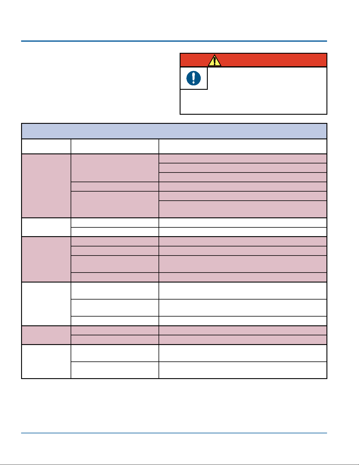
The following charts should be used when trouble-
shooting operational problems. If these suggested
troubleshooting procedures do not resolve the
problem, see the Service Instruction on Page 18.
Exercise extreme caution when
troubleshooting the electrical components
of the deliver unit. When testing, always
WARNING
disconnect the external power. When electrical
power is required, safety precautions must be
followed.
Delivery Head
Symptom Possible Cause(s) Solution
Unit will not
turn on. No air to master switch Open stop valve in oor utility box.
Open and adjust air regulator to 80 PSI.
Check for pinched red 1/8" tubing in umbilical.
Faulty master switch Turn switch to ON position and verify air ow.
Faulty air pilot valve Verify an air supply to top tting of valve.
If air is present at top tting of valve, verify air to foot
control tubing. If no air at tubing, valve is defective.
Unit has no
electric power No building power Check main circuit supply or contact electrician.
Improper outlet voltage Verify proper outlet voltage in USC.
Unit has no air Unit is not turned on. Ensure master switch is in ON position.
Air stop valve is closed. Turn stop valve ON and verify 80 PSI is on air gauge.
Pinched air line Check for pinched or restricted 1/4" red tubing from oor
utility box to cart.
Faulty air pilot valve Check barbs for blockage. If none, replace valve.
No water
(handpiece &
syringe)
Master switch is in OFF
position. Turn switch to ON position.
Pressure regulator is not
adjusted. Ensure clean water system gauge reads 40 PSI.
Slide clamp is clamping line. Move clamp to allow water ow through line.
Air in coolant
water Unit has not been purged. Purge water lines.
Faulty water control valve If unit was purged, replace water control valve.
Water ush
fails to operate. Water toggle is in OFF
position. Place toggle in ON position.
Faulty water ush toggle
valve If water is present at valve, but not owing, replace valve.
Simplicity®Cart
17
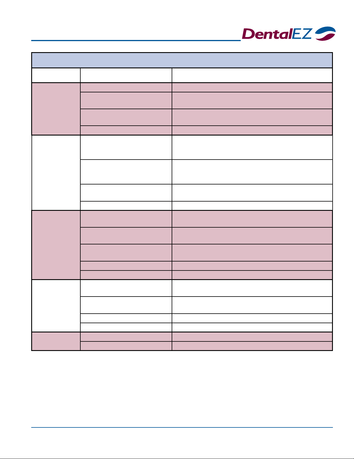
Section VII User Service Information
Handpiece
Symptom Possible Cause(s) Solution
Water dribbles
from handpiece
while in holder.
Faulty handpiece holder Repair or replace holder.
Pinched or restricted tubing to
holder Straighten or replace tubing.
Pinch valve diaphragm is
leaking Replace diaphragm.
Low air pressure Ensure air regulator gauge in oor box reads 80 PSI.
Water dribbles
from handpiece
after foot
control is
released.
Faulty water control valve Depress foot control, then release Remove black
tubing from water control valve. If dribble continues,
replace valve.
Faulty water relay in foot
control Turn unit OFF. Open foot control and inspect water re-
lay block. If piston is not damaged and is moving freely,
stretch the spring. Reassemble and retry foot control.
Pinched or restricted tubing
from foot control Straighten or replace tubing.
Low air pressure Ensure air regulator gauge in oor box reads 80 PSI.
No ber optic
light at
handpiece
Power transformer is not
plugged in. Plug transformer into designated receptacle in USC.
Internal wires in control head
and/or USC are not connected Check connections in control head and/or USC.
No signal air to ber optic
lamp control Check for pinched or restricted tubing.
Faulty transformer Check output for 9V.
Faulty bulb Replace bulb.
No coolant
water at any
handpiece
Coolant water adjustment
valves are closed. Turn valve counterclockwise to open valve.
Water toggle on foot control is
in the OFF position. Flip toggle to the right for the ON position.
Slide clamp is clamping line. Move clamp to allow water ow through line.
Pinched or restricted tubing Straighten or replace tubing.
No coolant air
to handpiece Slide clamp is clamping line. Move clamp to allow air ow through line.
Pinched or restricted tubing Straighten or replace tubing.

Simplicity®Cart
18 Installation,OperationandCareManual
Section VII User Service Information
Service Instruction
If the problem is not addressed or cannot be iso-
lated by performing the suggested troubleshooting
procedures, contact your local DentalEZ full-service
dealership. (See Limited Warranty, Page 24.) Be prepared
to supply the following product information:
•Model Name
•Model Number
•Serial Number
(The serial number label is located on the underside of
the cart.)
•Date of Installation
Disposal of Equipment
Before servicing, always disconnect the
external power by unplugging the unit from
the power receptacle.
WARNING
The DentalEZ Technical Service Department is
available to supply service personnel with any
additional information or instructions needed to
repair or maintain the dental delivery system.
NOTICE
Disposal and Decommissioning of
DentalEZ products:
Note: All local regulatory requirements
for disposal and decommissioning of
equipment apply.
Electrical Salvage: Remove ber optic
controller and transformer.
Metal Salvage: Remove all aluminum and
steel components for recycle as metal
salvage.
Plastic Salvage: Remove all plastic
components for recycle as plastic salvage.
Biologically Contaminated Salvage: Oral
extraction lines should be handled with
precaution and disposed of appropriately.
Non-Salvage Components: All other
material unsuitable for recycling should
be disposed of properly.
Handpiece(continued)
Symptom Possible Cause(s) Solution
No drive air Drive air ow adjustments on
pinch valves are closed. Using a screw driver, turn adjustment screw counter-
clockwise to adjust drive air pressure. Set to
manufacturer's recommended pressure.
Faulty handpiece holder valve If pinch valve does not release with handpiece out of
holder and tubing to holder is not restricted, replace
hanger valve.
Faulty foot control Depress foot control. If no air is present, repair or
replace foot control
Pinched or restricted tubing Straighten or replace tubing.
Simplicity®Cart
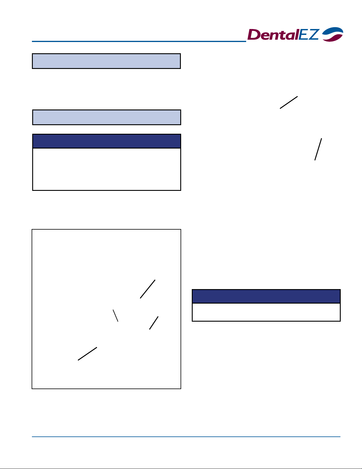
19
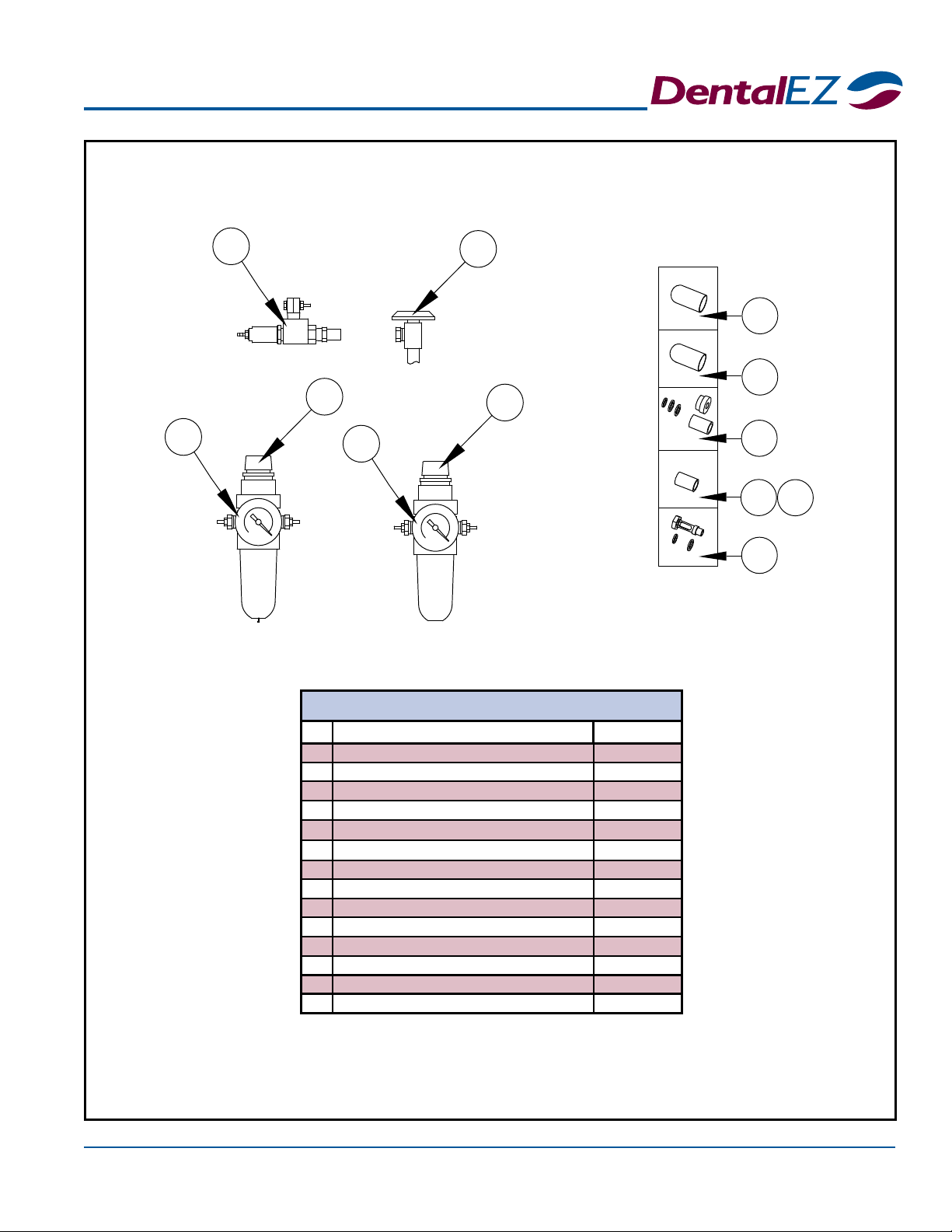
Section VIII Parts List/Diagrams
60 0
160 0
*5
2*1
4
3
*6
*10
7
*8
*9
12
11
*OptionalEquipment
# Part/Kit Name Part/Kit No.
*1 Water Actuator Valve 3801-637
2 Stop Valve 3800-960
3 Air Regulator 3801-638
4Air Pressure Gauge 3800-534
*5 Water Regulator 3802-107
*6 Water Pressure Gauge 3800-533
7 Air Regulator Bowl - Watts 3802-267
*8 Water Regulator Bowl - Watts 3802-268
*9 Water & Air Regulator Repair Kit - Watts 3802-273
*10 Water Regulator Filter - Watts 3802-270
11 Air Regulator Filter - Watts 3802-271
12 Regulator Retainer - Watts 3802-272
*Water Regulator Gauge Repl. Kit - Watts 3802-269
Air Regulator Gauge Repl. Kit - Watts 3802-266
Utility Service Center
Other manuals for Simplicity
1
This manual suits for next models
1
Table of contents
Other DentalEZ Medical Equipment manuals


