OXTS RT-UPS User manual

Confidently. Accurately.
RT-UPS
Uninterruptible
Power Suppl
y
User Manual

2 Oxford Technical Solutions
Legal Notices
Information furnished is believed to be accurate and reliable. However, Oxford
Technical Solutions Limited assumes no responsibility for the consequences of use of
such information nor for any infringement of patents or other rights of third parties
which may result from its use. No license is granted by implication or otherwise under
any patent or patent rights of Oxford Technical Solutions Limited. Specifications
mentioned in this publication are subject to change without notice and do not represent
a commitment on the part of Oxford Technical Solutions Limited. This publication
supersedes and replaces all information previously supplied. Oxford Technical
Solutions Limited products are not authorised for use as critical components in life
support devices or systems without express written approval of Oxford Technical
Solutions Limited.
All brand names are trademarks of their respective holders.
The software is provided by the contributors “as is” and any express or implied
warranties, including, but not limited to, the implied warranties of merchantability and
fitness for a particular purpose are disclaimed. In no event shall the contributors be
liable for any direct, indirect, incidental, special, exemplary, or consequential damages
(including, but not limited to, procurement of substitute goods or services; loss of use,
data, or profits; or business interruption) however caused and on any theory of liability,
whether in contract, strict liability, or tort (including negligence or otherwise) arising in
any way out of the use of this software, even if advised of the possibility of such
damage.
Copyright Notice
© Copyright 2015, Oxford Technical Solutions.
Revision
Document Revision: 150609 (See Revision History for detailed information).
Contact Details
Oxford Technical Solutions Limited
77 Heyford Park
Upper Heyford
Oxfordshire
OX25 5HD
United Kingdom
Tel: +44 (0) 1869 238 015
Fax: +44 (0) 1869 238 016
Web: http://www.oxts.com
Email: support@oxts.com

RT-UPS User Manual
Revision: 150609 3
Warranty
Oxford Technical Solutions Limited warrants the RT-UPS product to be free of defects
in materials and workmanship, subject to the conditions set forth below, for a period of
one year from the Date of Sale.
‘Date of Sale’ shall mean the date of the Oxford Technical Solutions Limited invoice
issued on delivery of the product. The responsibility of Oxford Technical Solutions
Limited in respect of this warranty is limited solely to product replacement or product
repair at an authorised location only. Determination of replacement or repair will be
made by Oxford Technical Solutions Limited personnel or by personnel expressly
authorised by Oxford Technical Solutions Limited for this purpose.
In no event will Oxford Technical Solutions Limited be liable for any indirect,
incidental, special or consequential damages whether through tort, contract or
otherwise. This warranty is expressly in lieu of all other warranties, expressed or
implied, including without limitation the implied warranties of merchantability or
fitness for a particular purpose. The foregoing states the entire liability of Oxford
Technical Solutions Limited with respect to the products herein.

4 Oxford Technical Solutions
Table of contents
Introduction 5
Product features 5
Description 5
Scope of delivery 7
Connecting and disconnecting the internal battery 8
Connections 12
Operation 13
LED definitions 13
Extended storage 13
RT-Range 14
Specification 15
Conformance notices 16
Regulator testing standards 16
Safety notices 17
Battery information 17
Transport by sea 18
Transport by air 18
Disposal / End of Life 18
Revision history 19

RT-UPS User Manual
Revision: 150609 5
Introduction
The RT-UPS is an uninterruptible power supply designed to prevent brown-out and
black-out conditions affecting our inertial navigation system (INS) products in real-
world applications. It supplies 12 volts at two amps for up to two minutes in vehicles
during engine cranking or if the driver stalls the engine and the ignition is turned off.
The RT-UPS is suitable for use with all INS products from OxTS.
Product features
Benefits of using an RT-UPS are:
Wide range of input voltage (9–48 V)
Brown-out and black-out protection during cranking
No need to re-initialise and warm-up system if power is accidentally cut
Internal battery charges while supplying the output
Isolated output
Transient protection for equipment
Description
The RT-UPS activates when power is applied to its input. If the input supply is
subsequently interrupted, or drops too low, the RT-UPS continues to output a constant
12 volts for up to two minutes using its internal battery. This prevents brown-outs
during vehicle cranking, and black-outs if the auxiliary power socket is accidentally
disconnected. In this way the INS continues to operate and there is no need to re-
initialise or perform additional warm-ups.
When the input power supply is absent a warning buzzer will sound and the RT-UPS
will continue to supply power to the output. If the RT-UPS does not detect a load on
the output the RT-UPS will turn off immediately and the buzzer will stop.
If the input power supply is restored within two minutes, the RT-UPS will revert back
to the vehicle’s power supply and charge the battery (if necessary). If the input power
supply is absent for longer than two minutes, the RT-UPS will stop the output power
and the “No Power” LED will illuminate for up to 10 minutes.
If the internal temperature of the enclosure exceeds approximately 75°C, then output
power will be turned off and the RT-UPS will enter standby for five minutes. It is not
possible to exit this mode—except by waiting five minutes.

6 Oxford Technical Solutions
The RT-UPS will try to charge its internal battery whenever an input power supply is
present and charging is necessary. The internal battery is protected against charging
outside of its specified charging temperature range.
If the battery temperature exceeds approximately 65°C, charging will be suspended
until the temperature falls to around 60°C. If the battery temperature falls below
approximately 0°C, charging will be suspended until the temperature reaches
approximately 5°C.
If the battery temperature approaches the lower threshold, the fan is temporarily
disabled to avoid unnecessary cooling that might prevent charging by actually holding
the battery at a low temperature.

RT-UPS User Manual
Revision: 150609 7
Scope of delivery
Table 1 lists the parts that are delivered with an RT-UPS.
Table 1. Summary of components delivered with an RT-UPS
Qty Description
1 RT-UPS unit
1 RT-UPS user manual

8 Oxford Technical Solutions
Connecting and disconnecting the internal battery
Air transportation regulations require that battery products are disconnected while in
transit. The RT-UPS is shipped with the internal battery disconnected. The battery will
need to be connected before the RT-UPS can be used. These instructions can be used to
connect and disconnect the battery.
There are two versions of the RT-UPS. Newer models can be identified by the large
battery isolation switch on the top panel. This switch connects and disconnects the
internal battery. In normal operation the switch should remain in the on position “I”,
however, when being transported by air, the switch should be set to the off position “0”
to isolate the battery.
Older versions of the RT-UPS require some disassembly in order to access the battery.
Although the RT-UPS does not need to be opened in a full electrostatic free
environment, you should take care to discharge yourself by touching the metal case
before touching any of the internal components.
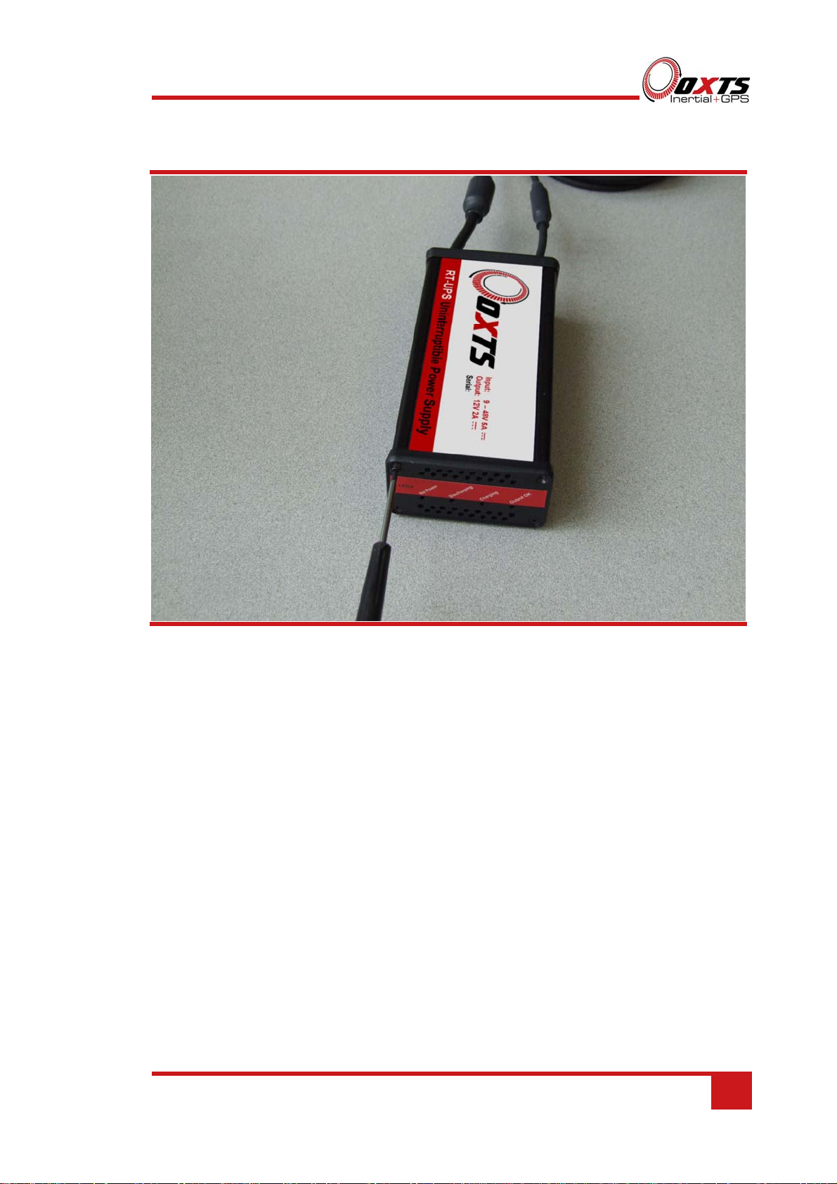
To open the older model RT-UPS, undo the four front panel screws using a No.1
Philips screwdriver as shown in Figure 1. Occasionally the two screws on the rear panel
also need to be undone to remove the lid.

RT-UPS User Manual
Revision: 150609 9
Figure 1. Removing the front panel screws on the older model RT-UPS
Remove the front panel and slide the lid off the RT-UPS, as shown in Figure 2.

10 Oxford Technical Solutions
Figure 2. RT-UPS showing the battery connector
Connect the battery wires to the socket on the circuit board as shown in Figure 3. The
connector can only be fitted one way round; take care not to force it incorrectly. Slide
the lid back in place, fit the front panel and replace the four screws. The battery will
now be connected correctly.
Before transporting by air disconnect the battery.
The battery should only be replaced by OxTS because the temperature sensor needs to
be fitted correctly.

RT-UPS User Manual
Revision: 150609 11
Figure 3. Battery connector fitted correctly

12 Oxford Technical Solutions
Connections
The RT-UPS has two leads that need to be connected for correct operation. The pin
connections are shown in Table 3 and Table 4.
The auxiliary power plug fitted to the RT-UPS’s input cable contains a five amp fuse,
which is required as part of the input protection circuit. If the fuse in the plug needs to
be replaced, it should be replaced with the Littelfuse model specified in Table 2.
Table 2. Replacement fuse
Parameter Specification
Manufacturer Littelfuse
Part Number 0214005
Description 5 A Torpedo Type Fuse
Dimensions 25 × 6 mm Ø
Voltage Rating 36 V
Table 3. Input power lead pin configuration
Pin Direction Description
1 Input Power in, 9–48 V dc. This pin is the tip of the connector (red wire).
2 Input Input ground (black wire).
Connector: Automotive universal fused auxiliary power plug (cigar lighter plug)
Table 4. Output power lead pin configuration
Pin Direction Description
1 Output Power output, 12 V, 2 A (brown wire).
2 Output Power output, 12 V, 2 A (white wire).
3 Output Output ground, isolated from input (blue wire).
4 Output Output ground, isolated from input (black wire).
Connector: Binder Series 763, 4-way, socket, M12

RT-UPS User Manual
Revision: 150609 13
Operation
Mount the RT-UPS so the fan and air vent holes are not covered—allowing heat to be
removed from the internal components.
To operate the RT-UPS, connect the output connector (Binder Series 763) to the
product that needs a stable 12 V power supply. Insert the input connector (auxiliary
power plug) into the vehicle’s auxiliary power socket. The input power supply can be
disconnected at any time. To stop the output power early, disconnect the INS from the
output power connector.
It is not recommended to operate an RT-UPS with an input voltage lower than nine
volts as this may result in an unstable operation that could damage the internal battery.
When a load is connected, the RT-UPS will warn when under-voltage conditions exist
by sounding the internal buzzer.
LED definitions
Table 5 lists the definitions of the LEDs on the RT-UPS. As a special condition, all
LEDs flash when the RT-UPS has overheated.
Table 5. LED definitions
LED label Description
No power Lit when there is no power available in the internal battery to supply the
output.
Discharging Lit when power is being supplied from the internal battery.
Charging Lit when charging. Flashing at 1 Hz means fast charging, continuously on
means trickle charging. A single fast flash when too cold to charge and a
double fast flash when too hot to charge.
Output OK Output power on.
Note: Older models prior to January 2015 have a slightly different charging definition. These have a slow
flash when charging at the fast rate and lit when charging at the standard rate. If you are unsure, please
contact OxTS and provide the serial number of your device.
Extended storage
The battery life of the RT-UPS is reduced if it is left discharged for a long period of
time. When leaving the RT-UPS for long periods, it should be charged monthly.

14 Oxford Technical Solutions
RT-Range
When using the RT-UPS with RT-Range S or standard RT-Range products, care should
be taken when connecting the systems. The RT-UPS should be connected between the
RT-Range Hunter system and the RT. It should not be connected between the power
supply and the RT-Range Hunter system as the current draw will be too much and may
damage the RT-UPS. Figure 4 illustrates the correct connection set up.
Figure 4. Connection set-up with RT-Range or RT-Range S

RT-UPS User Manual
Revision: 150609 15
Specification
The specifications for the RT-UPS are shown in Table 6.
Table 6. Specifications
Parameter Value
Operating voltage range19–48 V dc
Output voltage 12 V dc
No load detection current 200 mA
Maximum output current 2 A
Output power 24 W
Efficiency >60%
Fuse25 A (yellow, continental style)
No supply operation Up to two minute
No supply indication Up to 10 minutes
Internal battery Nickel-metal hydride, 12 V nominal (10 × 1.2 V
cells, Varta 10V600HR)
Battery charge time 1.5 hours typical
Transient protection Yes
Short circuit protection Yes
Supply reversal protection Yes (will blow fuse)
Dimensions (mm) 170 × 81 × 48 (excluding cables)
Weight 0.9 kg (including cables)
Operating temperature range -10–50ºC
Internal over heat temperature 75ºC typical
Upper charging temperature 65ºC typical
Lower charging temperature 0ºC typical
Environmental protection None
1The 9 V minimum operating voltage is defined at the connector end of the input cable. Extensions and
connections to the source from the connector will increase the voltage dropped in the cabling and
consequently the minimum required operating source voltage. The supply should ideally be rated to at
least 10 A output.
2The 5 A fuse in the auxiliary power plug is rated for 5 A continuous current with 10 A rating under
intermittent operation.

16 Oxford Technical Solutions
Conformance notices
The RT-UPS complies with the radiated emission limits for 47CFR15.109:2010 class A
of Part 15 subpart B of the FCC rules, and with the emission and immunity limits for
class A of EN 55022. These limits are designed to provide reasonable protection
against harmful interference in business, commercial and industrial uses. This
equipment generates, uses and can radiate radio frequency energy and, if not installed
and used in accordance with the instructions, may cause harmful interference to radio
communications. However, there is no guarantee that interference will not occur in a
particular installation. If this equipment does cause harmful interference to radio or
television reception, which can be determined by turning the equipment off and on, the
user is encouraged to try to correct the interference by one or more of the following
measures:
Re-orient or relocate the receiving antenna
Increase the separation between the equipment and the receiver
The RT-UPS conforms to the requirements for CE.
Regulator testing standards
47CFR15.109:2010 class A (radiated emissions)
EN 300 440-1:2008, test methods 8.3.2 (conducted emissions) and 8.3.3 (radiated
emissions)
EN55022 class A according to standard EN 301 489-1:2008 (conducted
emissions)
EN6100-4-3 criterion A according to standard EN 301 489-1:2008 (radiated
immunity)
ISO7637-2 criterion B, 12 V and 24 V according to standard EN 301 489-1:2008
(vehicular transients and surges immunity)
EN60950-1:2006 (safety)
A11:2009 (safety)

RT-UPS User Manual
Revision: 150609 17
Safety notices
Do not block the apertures in the box otherwise overheating will occur, which
will eventually result in thermal shutdown of the device.
Do not obstruct the internal fan.
If the unit becomes excessively hot please unplug the device and allow it to cool.
Do not replace the fuse in the auxiliary power plug with anything other than a
five amp fuse. If another connector is used then make sure that a five amp fuse is
included in the positive supply.
Do not deliberately short circuit the outputs.
Do not short circuit the internal battery.
Do not throw or cause impact to the RT-UPS as it contains a battery.
Do not burn.
The enclosure will become warm while in use; allow heat to be ejected from the
enclosure.
Do not dispose of in domestic waste.
Do not ingest the battery.
Do not allow the product to become wet or immersed in water.
Recommended storage temperature 20°C.
Battery information
In the event of a faulty battery, a replacement can be sent out from OxTS on request
along with instructions on how to change the battery for the user.
The following safety information has been provided by the battery manufacturer.
1. The only battery replacement is a Varta 10V600HR (To Varta drawing no.
074530).
2. Keep out of the reach of children. If swallowed, contact a physician at once.
3. Do not reverse the battery connections. Strictly follow the signs + and – shown on
batteries and appliances. If batteries are put in the wrong way they are bound to

18 Oxford Technical Solutions
become hot very quickly. This can lead to gas or toxic material leakage and/or to a
violent rupture.
4. Do not incinerate or mutilate otherwise the batteries may burst or release toxic
material. Do not throw battery into open fire. This can cause violent rupture due to
the heat.
5. Do not deform batteries. Batteries are not to be crushed, drilled into or damaged in
any other way. This can lead to toxic material or gas leakage and/or violent rupture.
6. Do not short circuit the battery. This can lead to toxic material or gas leakage
and/or violent rupture.
7. The Battery should be disposed in accordance with local and state regulations.
Transport by sea
For sea transportation of nickel-metal hydride round cells there is an additional
requirement:
1. Batteries must not be stored in close proximity of external heating sources.
Transport by air
Any electrical battery or battery powered device, equipment or vehicle having the
potential of a dangerous evolution of heat must be prepared for transport so as to
prevent:
1. A short circuit. In the case of equipment, by disconnection of the battery and
protection of exposed terminals
2. Accidental activation.
The battery must be disconnected before transporting by air.
Disposal / End of Life
For disposal of the battery, take to local authority recycling centre or contact OxTS for
advice. The battery waste code is 160605, “Other batteries and accumulators (nickel-
metal hydride batteries)”.

RT-UPS User Manual
Revision: 150609 19
Revision history
Table 7. Revision history
Revision Comments
100816 Initial version (draft only)
110607 First release
130613 Updates, discharge time reduced to one minute
131125 Minor updates, RT-Range disclaimer
140211 Changed input power lead wire colours. Added note about replacement battery.
141204 Updated to show improved discharge specification, notes to advise on operation.
150609 Updated for new battery isolation switch
Other manuals for RT-UPS
1
Table of contents
Other OXTS UPS manuals
Popular UPS manuals by other brands

Uninterruptible Power Supplies
Uninterruptible Power Supplies Online UPS 1K user manual

Microcare
Microcare 1kW24V manual

sinercom
sinercom LION100K user manual

Vertiv
Vertiv Liebert PSA5 Installation and user guide

LEGRAND
LEGRAND KEOR SPX Series installation manual

Minuteman
Minuteman Pro Series owner's manual