9
OPERATION
BEFORE ATTACHING OR REMOVING ANY ACCESSORIES FROM THE TOOL,
BE SURE TO DISCONNECT THE TOOL FROM THE POWER SUPPLY.
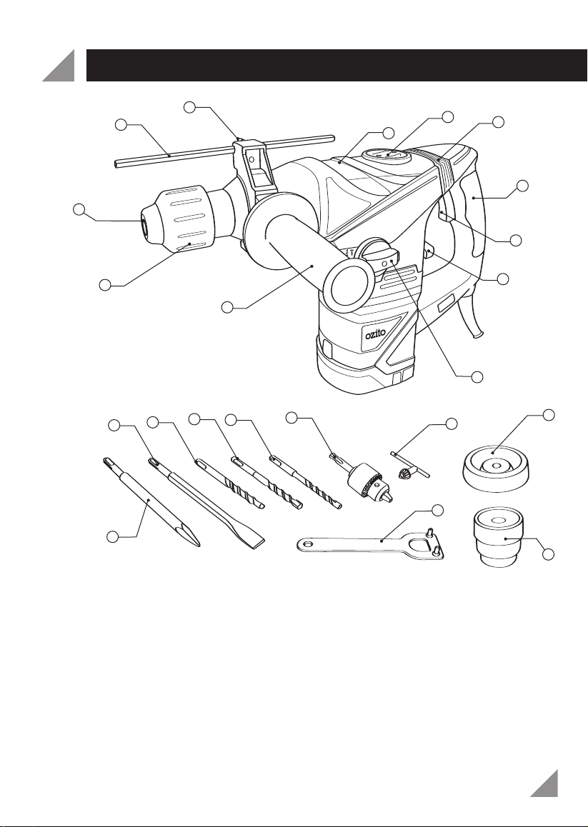
Side handle
The side handle (11) will provide additional control, support and guidance for the tool.
The side handle (11) is adjustable to any position around the 360º handle collar mount.
Loosen the side handle (11) grip by rotating it anti-clockwise to the handle collar
mount. Slide the collar of the handle over the accessory locking sleeve (12) and onto
the handle collar mount of the tool. Tighten the side handle (11) by turning the handle
grip clockwise.
Depth rod
The depth rod (2) allows you to drill holes to a predetermined depth. Loosen the depth
rod locking knob (3) by turning it anti-clockwise. Feed the metal depth rod (2) through
the hole in the side handle housing (11). Adjust the metal depth rod (2) so the chosen
drill bit currently assembled to the tool extends beyond the end of the metal depth rod
(2) to the required drilling depth. To secure the metal depth rod (2) into position, tighten
the depth rod locking knob (3) clockwise until tight. Once the metal depth rod (2) has
been set, proceed to drill the hole until the end of the metal depth rod (2) touches the
work piece, then remove the drill bit from the hole. The depth of the hole will be the
same as the depth the metal depth rod (2) was set to.
SDS+ Accessories
SDS+ accessories (13,14,15,16, 17 & 18) should only be secured into the SDS+
accessory holder (1) of the tool.
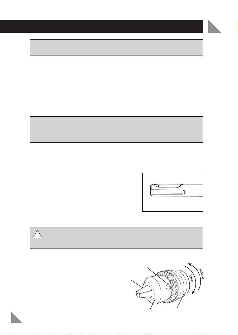
Important: The 13mm keyed chuck (18) is not intended for use with SDS+
accessories. SDS+ accessories should be fitted directly into the tools
accessory holder (1). Using SDS+ accessories in the 13mm keyed chuck (18) may
result in permanent damage to the chuck. Such damage will not be covered
under warranty.
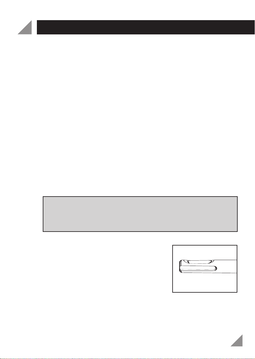
Fitting a SDS+ accessory
Prior to fitting a SDS+ accessory, remove any dust or
debris from the SDS+ shank of the accessory.
Pull the tools accessory locking sleeve (12) back towards
the body of the tool (away from the SDS+ Accessory
holder (1). Insert the desired SDS+ accessory into the
SDS+ accessory holder (1); rotate the accessory to
make sure it has been inserted as far as it will go, then
release the accessory locking sleeve (12).
With the tools accessory locking sleeve (12) having been released, check the
assembled SDS+ accessory has locked in place by trying to pull it out. SDS+
accessories will have a small amount of back and forth movement from the accessory
holder (1); this is normal.
Note: You may notice some “wobble” of the accessory when the tool is run in a no
load condition. This is due to the assembly of the quick change SDS+ tool holder. This
is normal; the bit automatically centres itself and produces accurate holes as soon as
load is placed upon the tool.
SDS+ Shank