Ozito ADWH-001 User manual

OZITO Australia/New Zealand (Head Office) 1-23 Letcon Drive, Bangholme, Victoria, Australia 3175. 0818
1
KNOW YOUR PRODUCT
ADWH-001
AUTO
DARKENING
WELDING
HELMET
3V LI-ION BATTERY
INSTRUCTION MANUAL
SPECIFICATIONS
Viewing Window: 92 x 42mm
Switch Time
(Light to Dark): 1/25,000s
Power Supply: 3V Li-Ion
(CR2032 Button Cell)
No. of Sensors: 2
Product Weight: 480g
ozito.com.au
1 2
6
4
8
3
7
5
9 10
IN ORDER TO MAKE A CLAIM UNDER THIS
WARRANTY YOU MUST RETURN THE PRODUCT
TO YOUR NEAREST BUNNINGS WAREHOUSE
WITH YOUR BUNNINGS REGISTER RECEIPT.
PRIOR TO RETURNING YOUR PRODUCT
FOR WARRANTY PLEASE TELEPHONE OUR
CUSTOMER SERVICE HELPLINE:
Australia 1800 069 486
New Zealand 0508 069 486
1 YEAR REPLACEMENT WARRANTY
Your product is guaranteed for a period of 12 months from the
original date of purchase and is intended for DIY (Do It Yourself) use
only. If a product is defective it will be replaced in accordance with the
terms of this warranty. Warranty excludes consumable parts.
WARNING
The following actions will result in the warranty being void.
• If the tool has been operated on a supply voltage other than that
specified on the tool.
• If the tool shows signs of damage or defects caused by or
resulting from abuse, accidents or alterations.
• Failure to perform maintenance as set out within the instruction
manual.
• If the tool is disassembled or tampered with in any way.
• Professional, industrial or high frequency use.
WARRANTY
TO ENSURE A SPEEDY RESPONSE PLEASE
HAVE THE MODEL NUMBER AND DATE OF
PURCHASE AVAILABLE. A CUSTOMER SERVICE
REPRESENTATIVE WILL TAKE YOUR CALL
AND ANSWER ANY QUESTIONS YOU MAY
HAVE RELATING TO THE WARRANTY POLICY
OR PROCEDURE.
The benefits provided under this warranty are in addition
to other rights and remedies which are available to you at law.
Our goods come with guarantees that cannot be excluded at law. You
are entitled to a replacement or refund for a major failure and for
compensation for any other reasonably foreseeable loss or damage.
You are also entitled to have the goods repaired or replaced if the
goods fail to be of acceptable quality and the failure does not amount
to a major failure.
Generally you will be responsible for all costs associated with a claim
under this warranty, however, where you have suffered any additional
direct loss as a result of a defective product you may be able to claim
such expenses by contacting our customer service helpline above.
1 Solar Panel
2 UV/IR Filter
3 Arc Sensor
4 Shade Number Adjustor
5 Mask Angle Adjustor
6 Auto Darkening Test Button
7 Low Battery Indicator
8 Delay Time Control
9 Sensitivity Control
10 Lithium Battery Slot
WELDING HELMET

1
Note: The Test function will not
work if the Shade Number
Adjustor is set to ‘Grind’.
1. BATTERY CHECK 2 . UV/IR FILTER
SETUP & PREPARATION
WARNING! ENSURE THAT ALL OPERATING PARTS ARE
CLEAN AND UNDAMAGED BEFORE USE. SCRATCHED OF
BROKEN PARTS SHOULD BE REPLACED IMMEDIATELY.
TEST
Testing The Helmet
Replacing The Battery
1 Turn the Shade Number
Adjustor and set it anywhere
between 9 and 13.
1 A red light will appear when the charge in the button cell battery gets
too low.
2 Placeaatheadscrewdriver(notsupplied)intotheslotinthe
battery cap and turn it anti-clockwise to unlock it. Remove the cap.
3 Replace the used battery with a new CR2032 battery.
4 Replace the cap. Turn the cap clockwise to lock it in place.
2 Press the Auto Darkening Test
Button. The viewing window
shoulddarkenbrieybefore
returning to normal.
Note: Lightfromweldingshouldbesucienttochargethesolar-
assisted battery if the helmet is used regularly. If the helmet
is left in storage for long periods, it will need to be recharged
before use.
Charging The Helmet
1 To charge the helmet place it sunlight for 1 hour with the solar panel
directed towards the light.
Note: Remove the Protective Film from the Filter and charge the helmet
before use.

1
1
3 . ADJUSTING THE HEADBAND 4 . CONTROLS
ADWH-001
OPERATION
WARNING! ENSURE THE LOW BATTERY INDICATOR
LIGHT IS OFF AND THAT YOU HAVE USED THE ‘TEST’
FUNCTION BEFORE ATTEMPTING TO WELD.
MAX
MIN
MAX
MIN
Adjusting The Tightness
Shade Number Or Grind Selection
Delay Time
Sensitivity
Adjusting The Angle
1 To loosen the headband, depress the knob on the back of the
headband and turn counter-clockwise. The knob will pop back into
place when released.
1 The appropriate Shade
Number should be selected
based on the welding
process and arc current
being used. Refer to the
label on the inside of the
mask for guidance.
1 This setting adjusts the time
needed for the helmet to
switch back from full dark to
full light
.
2 To adjust, turn the Delay
Time control to the
appropriate setting.
1 This adjusts the sensitivity of
the helmet to ambient and
welding light levels.
2 To adjust, turn the dial to
the lowest setting and face
the helmet in the direction
of use, exposing it to the
surrounding light levels.
3 Gradually turn the dial clockwise until the lens darkens. Then turn
it counter-clockwise until slightly past the setting where the lens
clears.
2 To change the Shade Number, turn the knob to the appropriate
number.
1 To adjust the angle of the
mask, loosen the Mask Angle
Adjusters on both sides of the
mask.
2 To tighten the headband, depress the knob and turn it clockwise until
thehelmettssnuglyonyourhead.
2 Slide the cross pin forward or
backwards in relation to the
headband slots and set the
outer hooks onto one of the 5
pin options.
3 Retighten the knobs. Adjust the screw tightness so that the mask
canbeippedupordowneasilywhennudged,butremainsin
position otherwise.
Note: The adjustment knob is self-locking. Forced rotation without
depressingitrstwilldamagethegear.
Note: For grinding activities, set the Shade Number selector to GRIND.
Note: - The minimum delay time of 0.1-0.25s is suitable for spot, seam
or short welding.
- The medium setting is suitable for the majority of indoor and
outdoor welding activities.
- The maximum time delay of 0.85-1.0s is suitable for high
current welding or to prevent eye fatigue during long welding
sessions.
Note: Slight re-adjustment may be necessary for certain applications or
ifthelensisashingonando.
Note: The medium setting is suitable for the majority of indoor and
outdoor welding activities.
Note: When properly adjusted, your line of sight and the Angle Adjustor
Knobs should be connected by a straight line perpendicular to the
viewing window.

1
Changing The Inner Lens
If the metal bar is in place, follow Step 1 of Replacing The Outer Lens
to move it out of the way.
1.Usingyournailsoraatruler,
lift and remove the old inner
lens from its slot.
Note: Try to avoid getting
ngerprintsonthelenses.
2. Slide the replacement lens
back into the slot, ensuring
that all four corners of the lens
are securely under the corner
tabs.
Note: Only one side of the inner
lenshasaprotectivelmonit.
Ensure this side faces towards
the inside of the helmet otherwise you will be unable to remove the
lmoncethelensisinplace.
3.Removetheprotectivelmfromtheinnerlens.
4. Lower the metal bar back into
place. Pull it down and under
the tabs to lock the control unit
back into place.
Replacing The Outer Lens
Replacement lenses have been provided in case the original ones get
marked up during use.
1. On the inside of the helmet,
pull the metal bar down past
the tabs to release the control
panel unit.
2. Swivel the metal bar out of
the way.
2. Carefully lift the control
panel unit out of the way,
being careful not to touch or
scratchtheUV/IRlteronthe
underside of the control panel
unit.
3. Push down on the centre of
the outer lens from the inside.
This will allow you to squeeze
it past the tabs on the outside
of the helmet.
4. From the outside of the
helmet, slide one end of the
new outer lens into the groove
beneath the tabs. Gently push
down on the centre of the
lens from the inside and slide
it under the tab on the other
side of the panel.
6.Peelotheprotectivelmfrombothsidesoftheouterlens.
7. On the inside, slide the control panel unit back into its seat.
ADWH-001
1. CHANGING THE LENSES
MAINTENANCE
Push Down
WARNING! BE CAREFUL NOT TO SCRATCH THE
UV/IR FILTER AS THIS MAY IMPAIR THE AUTO-
DARKENING FUNCTION AND LEAD TO EYE
DAMAGE DURING USE.

ONLINE MANUAL
Scan this QR Code with your
mobile device to take you to
the online manual.
SAFETY WARNINGS
CARING FOR THE ENVIRONMENT
Power tools that are no longer usable should not be disposed of
with household waste but in an environmentally friendly way. Please
recycle where facilities exist. Check with your local council authority
for recycling advice.
Recyclingpackagingreducestheneedforlandllandrawmaterials.
Reuse of recycled material decreases pollution in the environment.
Please recycle packaging where facilities exist. Check with your
local council authority for recycling advice.
THIS MANUAL CONTAINS IMPORTANT SAFETY AND OPERATING INSTRUCTIONS FOR
YOUR WELDING HELMET.
1. The auto-darkening welding helmet is not suitable for laser welding and oxygen acetylene
welding.
2. Donotputthehelmetnearamesorindampplaces.
3. Beforeoperation,pleaseconrmthattheweldingorgrindingfunctioniscorrectlyselected.
4. CeaseusingthehelmetimmediatelyifthelterdoesnotdarkenonexposuretoUV/IR
light. Contact the manufacturer for further instructions.
5. Do not attempt to replace or modify parts of the helmet. Send it to an authorised repairer.
6. Donotremovethelterprotectiveplateorthelter.
7. Donotusealcohol,petrol,orthinnerstocleanthelter.
8. Do not immerse the helmet in water.
9. Optimum operating temperature is between -5 to 55oC(23to131oF).Theautodarkening
function may react slower outside of this range.
10. Sendthehelmettoanauthorisedrepairertoreplacetheprotectivelmsimmediatelyifit
is broken or scratched.
11. Sendthehelmettoanauthorisedrepairertoreplacethelterprotectiveplateimmediately
ifitisbrokenorscratched.Topreventdamagetothelter,donotusehardobjectsnearit.
12. Cleantheltersurface,sensorsandsolarcellsregularly.
13. This welding helmet does not provide protection against serious impact, explosives, or
corrosive liquid damage.
NOTE: Serious personal injury may occur if these warnings are ignored.
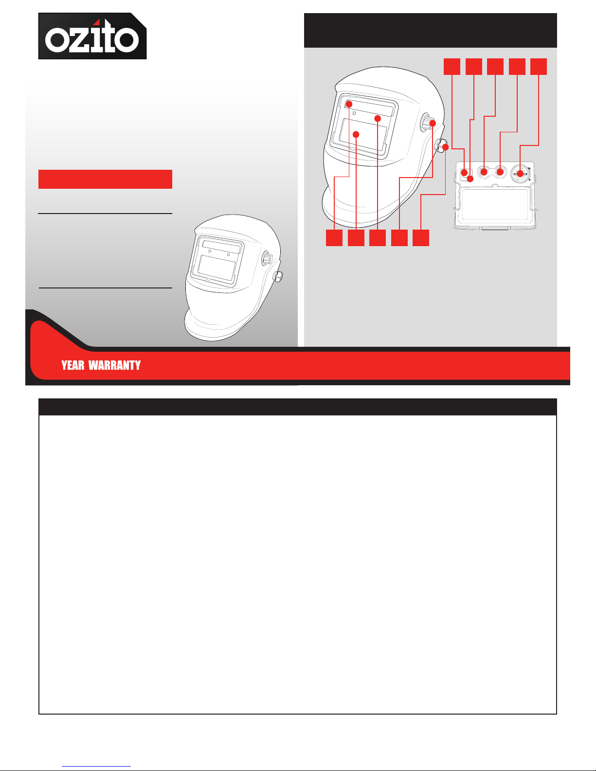
ADWH-001
CHANGING YOUR LITHIUM ION BATTERY
The CR2032 button cell battery has a service life of 5000 hours.
However it should be replaced if the Low Battery Indicator light
should come on. Refer to the Battery Check section of this manual for
instructions on how to do so.
FILTER DOES NOT DARKEN OR FLICKERS
Check that the Filter Protector & Filter is not scratched or dirty.
Check that the Arc Sensors are clear and unobstructed.
Check that the sensitivity is not set to MINUMUM.
Check that the Low Battery Indicator light is not lit.
FILTER REACTS SLOWLY
Check that the ambient temperature is within the operating range.
Check that the sensitivity is not set to minimum.
FILTER IS NOT CLEAR
Check that the Filter Protector is not stained.
Check that the Protective Film has been removed.
Check that there is enough ambient light in the work space.
Check that the Shade Number is set correctly.
HELMET IS SLIPPING
Check that the headband is adjusted correctly.
CheckthattheAngleAdjustorshavebeentightenedsuciently.
GENERAL MAINTENANCE
1. Cleanthelterregularlywithtissues,lenspaperorasoftcloth.
2. Use a neutral detergent to clean the helmet shell and sweat bands.
Note: Do not use corrosive solvents or gasoline to dilute detergent for
cleaning.
MAINTENANCE
TROUBLESHOOTING
Table of contents
Popular Welding Accessories manuals by other brands

EWM
EWM voltConverter 230/400 operating instructions

ESAB
ESAB MXH 315 PP instruction manual

Lincoln Electric
Lincoln Electric Fleetweld 47 datasheet

MAGNATECH
MAGNATECH Pipeliner II 609A Operating and maintenance instruction manual

Abicor Binzel
Abicor Binzel G3000 Warnings and Safety, Parts Breakdown, Hook-up Procedure, Specifications and Operation

EWM
EWM cool50 U42 operating instructions