ProArc CB-001 User manual
OWNER’S MANUAL
Important
:
Read these instructions before installing, operating or servicing this product.
MODEL
:
CB-001
STANDARD CONTROL BOX
Serial Number
:
15062500401 ~ and later
Revised date
:
July. 13th , 2015
UNITED PROARC CORPORATION
No. 3 Gungye 10th Road, Pingjen Industrial Park, Tel No:886 3 469 6600
Pingjen City, Taoyuan 324, Taiwan Fax No:886 3 469 4499
http://www.proarc.com.tw E-Mail:customerservice@proarc.com.tw
RD-886GE


TABLE OF CONTENTS
Introduction
Operator controls
Trouble shooting
Parts list
Circuit diagram
Revision
Limited warranty····················································································· i
1. Control panel····················································································· 1
2. Trouble shooting guide ········································································ 3
3.1 Control box (front)············································································· 5
3.2 Control box (rear)·············································································· 6
4.1 Control system ················································································· 7
Wiring diagram ······················································································ 8
Revisions····························································································· 9

LIMITED WARRANTY
UNITED PROARC CORPORATION warrants all new equipment to be free from defects in material and
workmanship for a period of one (1) year, provided that the equipment is installed and operated according to
instructions stated in this manual.
UNITED PROARC’s obligation under this warranty policy is expressly limited to the replace or repair, at its
option, of the defected part only. ProArc’s option to repair or replacement of a defected part under this
warranty shall be based on FOB Taiwan basis.
UNITED PROARC CORPORATION shall not be liable for any loss or consequential damage or express
accruing directly or indirectly from the use of equipment covered by this warranty.
This warranty supersedes all previous ProArc warranties and is exclusive with no other guarantees or
warranties expressed or implied.
This warranty excludes the consumable parts that are used in normal operation
i

T
T
TH
H
HI
I
IS
S
S
P
P
PA
A
AG
G
GE
E
E
I
I
IS
S
S
B
B
BL
L
LA
A
AN
N
NK
K
K
i
1.1 CONTROL PANEL
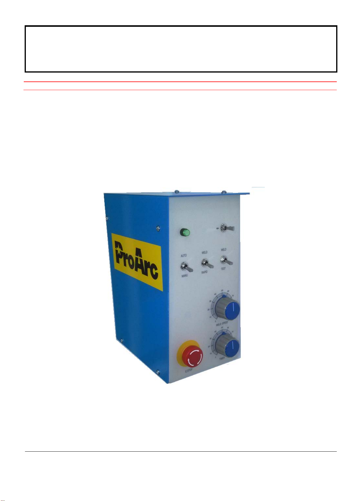
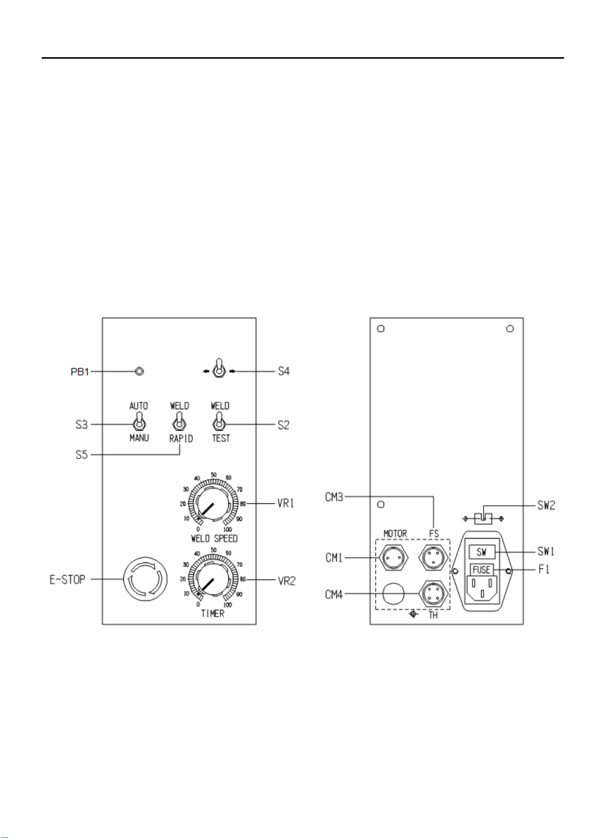
Front Panel:
E-Stop:Emergency stop button
PB 1:Push Button and Power ON signal
S 2:Weld / Test mode selection switch
S 3:Auto / Manual mode selection switch
S 4:Clockwise / counter clockwise selection switch
S 5:Weld/rapid speed selection switch
VR1:Welding speed adjustment
VR2:Welding timer adjustment
Rear Panel:
SW1:Power switch
SW2:Voltage selection switch
F1:Fuse(1A)
CM1:Motor connector (2Pin)
CM3:Foot switch connector (3Pin)
CM4:Welding source connector (4Pin)
1

1.1 CONTROL PANEL
1. Connect the power cord to the power socket located on the rear panel, turn on the power switch (SW1),
then push the PB1 button, the PB1’s LED should light up indicating power supply is ok.
﹡
Please make sure the E-Stop button is not pressed/activated before usage. All controls become
invalid when E-Stop button is pressed.
2. S2 ( WELD / TEST ) Switch enable / disable welding source activation output.
3. S3 ( AUTO / MANU ) Switch select the operation mode.
Manual ( MANU ):Turn table rotation is controlled by the foot switch
Automatic ( AUTO):The start of the rotation is activated by the foot switch, the duration of the rotation and
is controlled by the ( TIMER ) knob on the front panel from for a duration of (0~60
second).
4. S4 ( ←/ →) Direction switch select the direction of rotation (clockwise or counterclockwise.)
5. S5 ( WELD / RAPID ) Switch select the operating
Welding speed ( WELD ):Turn table rotation speed can be adjusted from(WELD SPEED)knob on the
front panel.
Full speed (RAPID):Turn table rotation speed is set at full speed.
﹡
Press E-Stop button in case of any emergency situation. All motion and procedure would stop
immediately. Reset the E-Stop button and push PB1 again after clearing the emergency
situation to return the system to operation mode.
2

2.1 TROUBLE SHOOTING GUIDE
SYMPTOMS
POSSIBLE CAUSES/REMEDIES
Power indicator light does
not illuminate. A. Wrong selection of input power:
Select the correct input power (110V or 220V)
B. Blown fuse:
Check the circuitry and find out the blown. and then, replace fuse.
C. Input power switch malfunction:
Check and replace the power switch.
D. Transformer has no output voltage:
(1) Check if the input voltage, it should be AC110V/ 220V.
(2) Measure CN8 for Pin 1 & 3, there should be 24VAC, and pin 2 & 3
should be 18VAC, if one of the voltage is not correct,
please replace a
new transformer.
E. The flat cable is damaged:
(1) Check relay board CN1 Pin 7 & 8, it should read 24VDC.
(2) Measure Front panel CN1 Pin 7 & 8, it should read 24VDC, if not,
replace the flat cable.
F. PB1 is damaged:
Keep PB1 pressed and measure front panel PB1’s connection (CN1’
s Pin
7 & 8). If no connection, replace a new PB1..
Motor has no motion. A. Motor coil is damaged:
Use ohm meter to measure CM1 female plug pin 1&2 and It should give
you 2 ohm. If 2 ohm doesn't exist, replace the motor.
B. Motor has power input, but no motion:
Measure CM1 male socket Pin 1 & 2 - if there is 6.5VDC, then replace a
new motor.
C. I/O board is damaged
:
(1) Check Relay board CN9 Pin 11&12, the reading should be about
6.5VDC voltage.
(2) Measure CM1 male socket Pin 1 & 2 - if there is no 6.5
VDC, replace a
new I/O board.
Welding action not
responsive. A. Weld/Test switch is damaged:
Switch to "Test" position and check if relay board D10 illuminates, if not,
please replace the front panel board.
B. Relay board is damaged.
Switch to "Test" position and check if relay board D10 illuminates, if yes
but has no action, please replace the relay board.
3

2.1 TROUBLE SHOOTING GUIDE
SYMPTOMS
POSSIBLE CAUSES/REMEDIES
Forward / Reverse
revolutions not functioning
correctly.
A. Footswitch is damaged:
(1) Measure footswitch connector Pin 1&2, step on the footswitch and
measure Pin 1&2 is shorted. if not, replace a new footswitch.
(2) Step on the footswitch and check if relay board D11 illuminates, if
yes ,but has no action, replace a new relay board.
B. Forward / Reverse revolution switch is damaged:
(1) Switch to "Forward" position and check if Relay board D3
illuminates, if not, please replace the front panel board.
(2) Switch to "Reverse" position and check if Relay board D4
illuminates, if not, please replace the front panel board.
C. K1 ~ K4 relay is damaged:
(1) Switch to "Forward" position and if Relay board
D3 illuminates but the
relay has no action, please replace the relay board.
(2) Switch to "Reverse" position and if Relay board
D4 illuminates, but the
relay has no action please replace the relay board.
Can not adjust speed. A. Motor control PCB is damaged:
(1) Check the motor control PCB. It should have an input voltage of
30VDC between DC+ & DC-.
(2) Adjustment weld speed, measure A1 & A2, it should read approx.
6.5VDC, if not, voltage replace the motor control PCB.
B. Weld / Speed switch is damaged (Weld /Full speed):
(1) Switch to Manual mode and adjust the weld speed dial to about 50%
of the full speed, then step on the footswitch.
(2) Switch to both weld and speed positions, the motor should respond
with slow and fast speeds respectively, if not then replace a new front
panel board.
C. The potentiometer is damaged:
(1) Detach the Front panel board CN2 connector, use ohmmeter to
measure Pin 1 & 2.
(2) Rotate the weld speed variable resistor's and check if the resistance
value is changing. If not, please replace VR1.
Weld timer not functioning A. T1 Timer is damaged:
(1) Switch to "Auto" position and step on the footswitch.
(2) CheckT1 the motion window of the timer, the "UP" signal should lit, if
not, please replace relay board.
B. T1 The Timer is unable to stop
:
(1) Detach the Relay board J1 connector, measure Pin 1&2.
(2) T Rotate the timer knob and see if the resistance between Pin 1&2 is
changing from 0~1M ohm. If not, please replace the VR2 (Timer
knob).
4
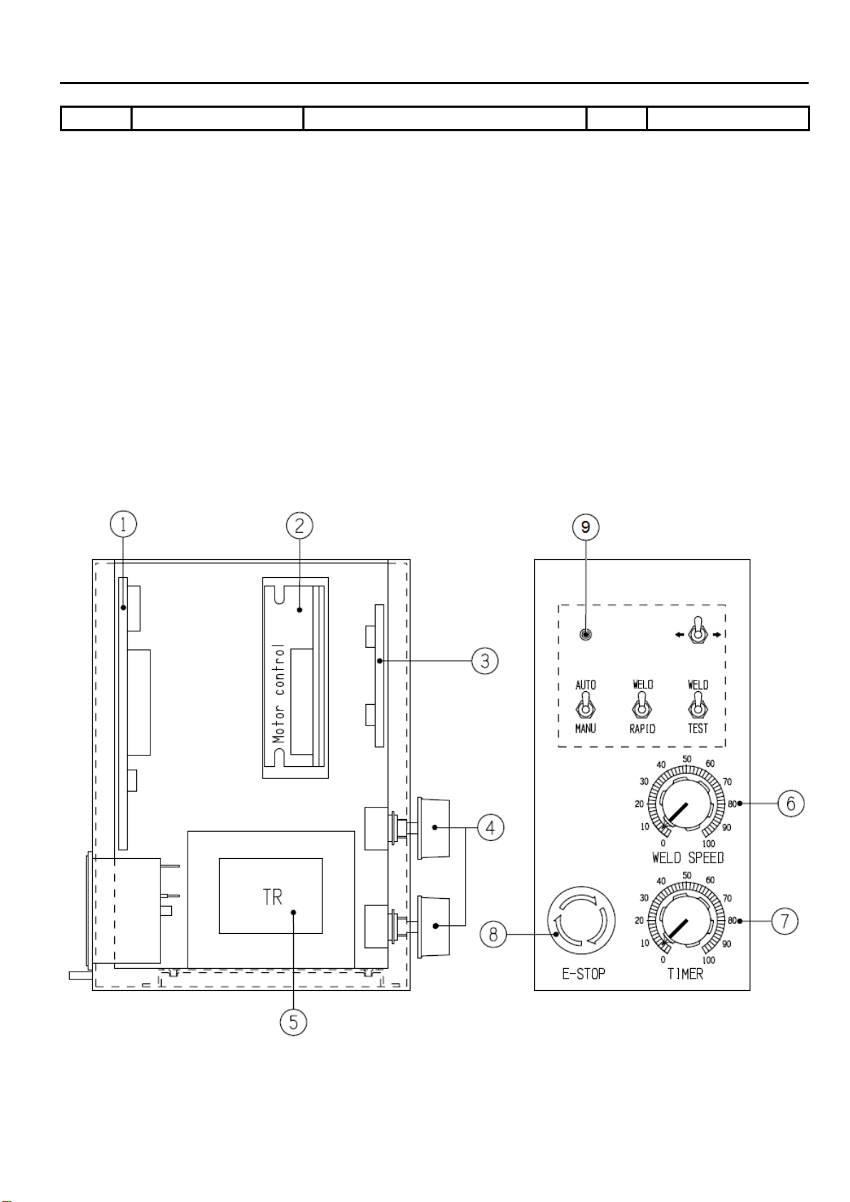
3.1 PART LIST — CONTROL BOX (FRONT)
Fig No.
Part No.
Description
Q’ty
Remark
1
*
6620-1124
Relay board
1
Relay board
2
*
6651-0011
Motor speed control board
1
Motor control
3
*
6621-2240
Front panel board
1
Front panel board
4
3216-0003
Knob (Blue)
2
Knob
5
*
3311-0039
Transformer
1
TR
6
*
3747-1001
Potentiometer
1
VR1
7
*
3747-1002
Potentiometer
1
VR2
8
*
3214-2009
E.S Push button
1
E-Stop
9
*
3271-3002-8
LED Push button
1
PB1
* Recommended spare parts
**Options
5

3.2 PART LIST — CONTROL BOX (REAR)
Fig No.
Part No.
Description
Q’ty
Remark
1
6620-1311 I/O Panel board 1 I/O board
2
3217-2002
Selection switch
1
SW2
3
3331-2001
Power entry module
1
SW1
4
*
3226-2001 Fuse 1A 20mm 2
5
5010-1020020-11 PMDC Motor with connector 1 CM1 Motor connector
6
**
3242-1101
Foot switch Assy cable 3M
1st
Foot switch Assy
7
**
3445-0001
Power cable
1st
Power cable
8
3123-2005 Female connector 4 pin 1 CM4 TH connector
*Recommended spare parts
**Options
6
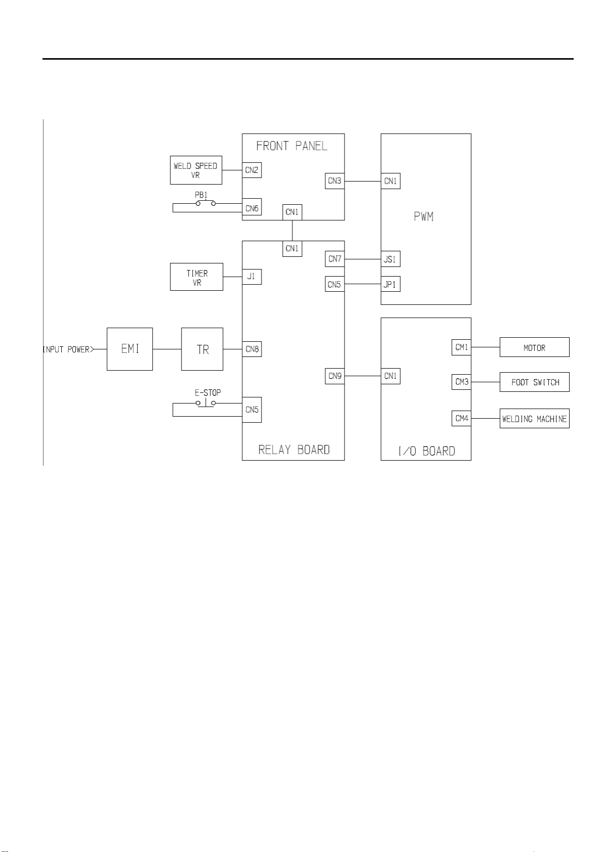
4.1 CONTROL SYSTEM
7
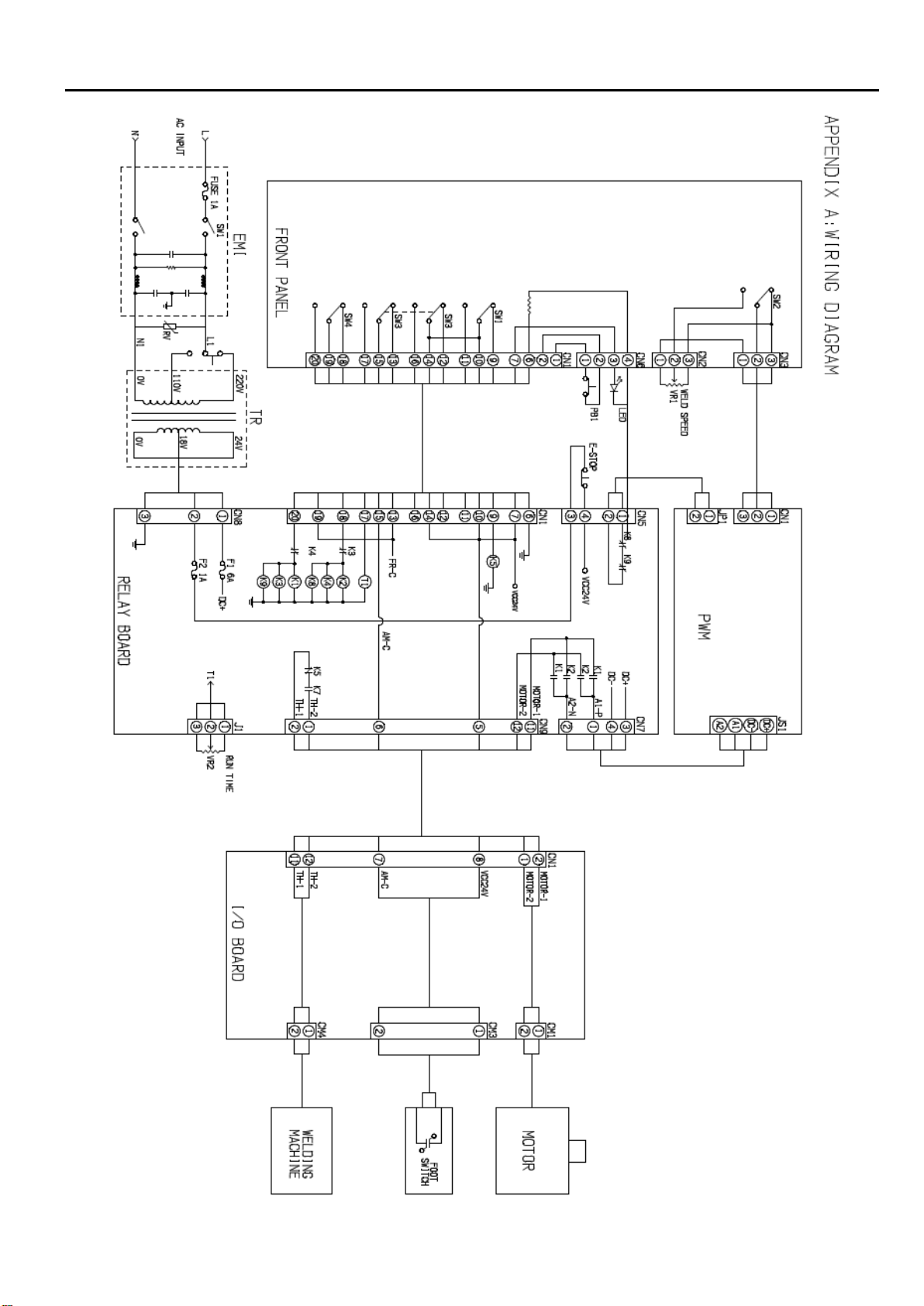
4.2 WIRING DIAGRAM
8

REVISIONS
Manual number
Print data
Changed page
Revisions
RD-886CE
Mar. 17, 2010
3.1 (P9~P10)
Adding
:
E-Stop
RD-886DE
Jul. 21, 2010
3.1 (P7~8)
Revised
:
6651-0001
→
6651-0011
RD-886DE
Jan. 03, 2011
3.1 (P5)
Revised
:
3311-0023
→
3311-0039(Number 2011~Later)
RD-886FE
Mar. 29, 2013
3.1 (P5)
Revised No.1
:
Relay board 6620-1122
→
6620-1123
RD-886GE
July. 7th, 2015
Add PB1 control and part list
9
This manual suits for next models
1
Table of contents
Other ProArc Welding Accessories manuals


Popular Welding Accessories manuals by other brands


Lincoln Electric
Lincoln Electric Miniflex Operator's manual

Harbor Freight Tools
Harbor Freight Tools CHICAGO ELECTRIC 46092 Owner's manual & safety instructions

Parweld
Parweld XR935H Instruction guide

CEVIK PRO
CEVIK PRO CE-PE1000/3XL instruction manual

SHINE
SHINE 5000 instruction manual

Abicor Binzel
Abicor Binzel ABIMIG 0 Series operating instructions


