P. M. Lighting Professional Series User manual

www.pmlighting.com info@pmlighting.com
Installation Manual
CS9300-LED
Professional Series
Landscape Lighting System

www.pmlighting.com info@pmlighting.com
READ THESE INSTRUCTIONS ENTIRELY BEFORE BEGINNING INSTALLATION!
Congratulations on your decision to purchase one of the finest quality LED landscape lighting systems on the
market today. When properly installed and maintained, this system will provide years of trouble free service
and allow you to illuminate your home like a professional. Just follow these easy steps to design and install
the CS9100 system and any add-ons or upgrades you may have purchased. For additional help and
information on installing your system, visit our web site at www.EasyAssemblyRequired.com.
WHAT’S INCLUDED:
Ϯeach CS937-LED Copper Bullet Directional Lights 200 feet Landscape Cable 14/2 gauge
3 each CS936-LED Copper Area/Path Lights 1 each Outdoor Timer with Photocell
ϰeach CSϵϯϯͲ> /ŶͲ'ƌŽƵŶĚtĞůů>ŝŐŚƚƐ 1 each Stake Driver Cap (Installation Tool)
ϭĞĂĐŚ^ϭϬϬdWƌŽͲ^ĞƌŝĞƐdƌĂŶƐĨŽƌŵĞƌ
TOOLS REQUIRED/RECOMMENDED FOR INSTALLATION:
Screwdriver (Flat & Phillips Head) Shovel
Wire Cutter Hammer
Wire Stripper 100-Ft Measuring Tape
Pliers Power Drill and Bits (3/16” bit for plastic anchors)
Dead Blow Mallet (for stake installation) Gloves
BASIC SYSTEM DESIGN STEPS:
LED landscape lighting is quite easy to install and is much easier than traditional halogen systems.
LED lighting allows the running of cables with less complications of the dreaded “voltage drop” that
occurs more readily with halogen systems and other higher wattage incandescent systems. Just
follow these four easy steps for a successful installation.
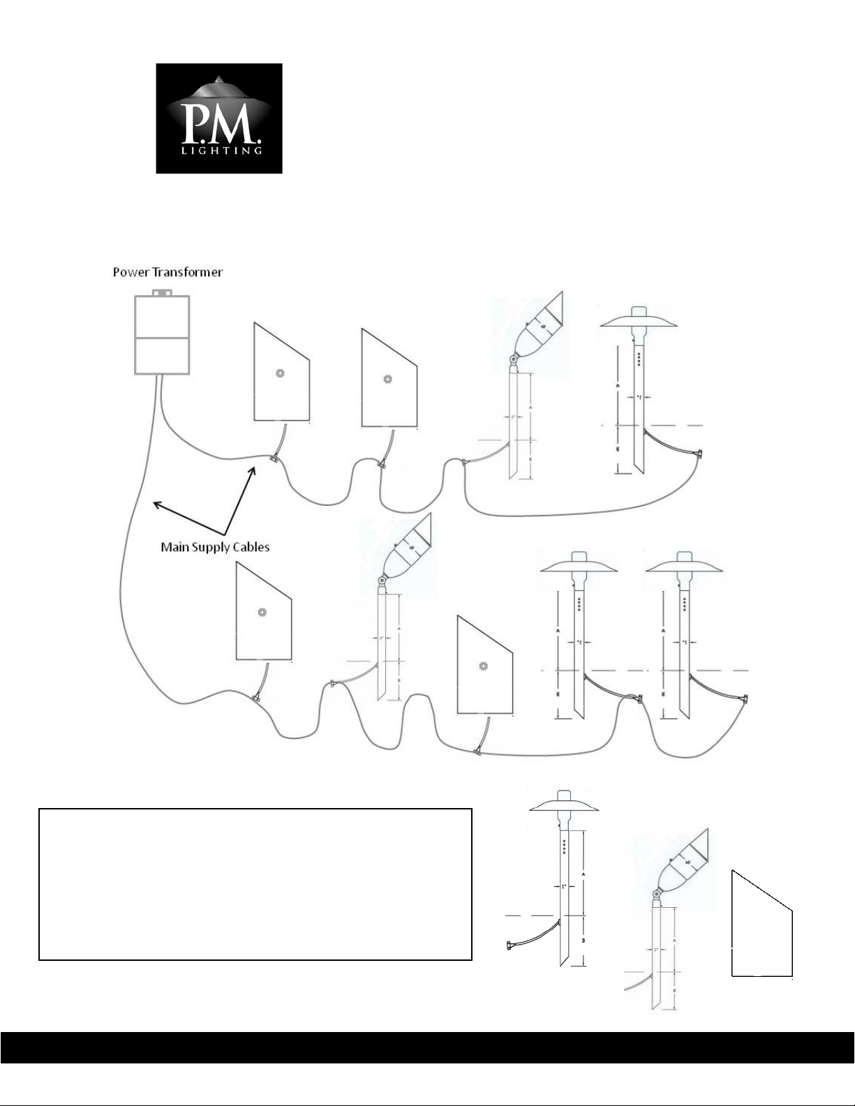
A. Determine the location of the power transformer before installation and make sure a suitable 115/120VAC
covered GFCI outlet marked “WET LOCATION” is within reach of the transformer power cord. Attach and
secure transformer to the wall a minimum of 12 inches above ground using screws and anchors (if needed).
Mounting screws are provided for your convenience.
B. Lay out the 14/2 gauge MAIN SUPPLY CABLE according to the Easy Design Guide on the next page, paying
close attention to where your fixtures are located and distances to determine the length of cable needed.
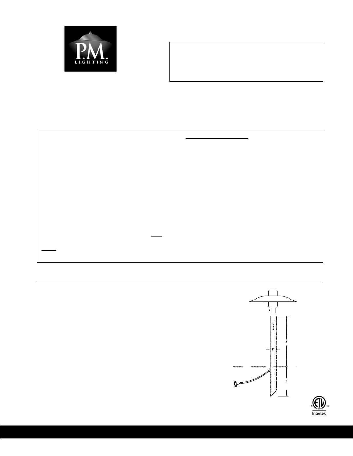
C. Install each luminaire according to the individual instruction sheets, attach each luminaire to the Main
Supply Cable using the attached easy connectors, and bury loose cable as desired (6 inches deep or less).
D. Plug Power Transformer into the Timer with Photocell, plug the timer into the GFCI outlet, and turn the
Timer dial to the desired setting for Dusk/Dawn, or Dusk On/ Off in 2, 4, 6, or 8 hours.
CS9300 Professional Series
LED Landscape Lighting System – pg. 1

www.pmlighting.com info@pmlighting.com
Easy Design Guide
Use the Easy Design Guide to help determine the best way to wire your fixtures to create optimal results in the
illumination of your home. Follow these simple rules for best results:
1. It is recommended that you use 2 MAIN SUPPLY CABLE runs from the transformer for best results and
easiest installation, especially when you need to install fixtures on both sides of the transformer.
2. For short distances from the transformer (under 60 feet), only a single MAIN SUPPLY CABLE may be used to
install this LED system for even easier installation. If the transformer is located on one end of the house,
simply run a cable from the transformer to the various lights, leaving a little extra slack to make burying the
cable easy.
3. DO NOT EXCEED the MAXIMUM WATTAGE listed for each length of MAIN SUPPLY CABLE used or the
voltage at the fixtures will be lower than required causing the LED to flicker or not light at all. If any lights,
especially on the end of the MAIN SUPPLY CABLE, do not light or experiences flickering, make sure the
transformer is on the HIGH setting (See #4 below) and check to make sure the quick connectors on each
light fixture are properly installed and are making a good connection.
4. Use the HIGH SETTING on the transformer to boost the secondary voltage for this system to provide
additional voltage. (See details in Transformer Installation Sheet)
5. SHORTER lengths for the MAIN SUPPLY CABLE lowersvoltage drop on the line while LONGER lengths
increases the voltage drop. Use the Line Length/Wattage Chart below to determine the maximum wattage
load for various lengths of the MAIN SUPPLY CABLE.
6. The total wattage for the CS9ϯ00-LED 9-Light System is only 55 watts, providing ample room on the
standard 100 watt transformer to add additional CS Professional Series LED fixtures to expand your system.
The chart below will help determine the maximum amount of fixtures you can have on the system when you
add up the total wattage from all fixtures on the line / system.
Total Length of Main
Supply Cable
Maximum Wattage
Available for Fixtures
CS9ϯ00-LED Fixtures &
Optional Add-ons
Individual Fixture
Wattage
50 Feet 90 watts
CS936-LED Path Light 3.0 watts
60 Feet 75 watts
CS937-LED Bullet Light 5.0 watts
70 Feet 60 watts
CS938-LED Deck Light* ϯϬ watts
80 Feet
55 watts
CS933-LED Well Light 9Ϭ watts
90 Feet 50 watts
*Sold Separately - Optional add-on fixtures are
100 Feet 45 watts
ŶŽƚŝncluded in the CS9ϯ00-LED 9-Light System.
Save these instructions!
CS9300 Professional Series
LED Landscape Lighting System – pg. 2

www.pmlighting.com info@pmlighting.com
Example of Wiring Plan
Save these instructions!
This example demonstrates the optimal wiring plan design, using
two (2) Main Supply Cables from the transformer to split the
fixtures into two (2) groups. For best results follow these tips:
1. Keep cables as short as possible.
2. Leave enough slack to make burying cable easier.
3. Make sure the Easy Connectors are tight to create a good
connection on the Main Supply Cable
CS936-LED = 3W
CS937-LED = 5W
CS9300 Professional Series
LED Landscape Lighting System – pg. 3
CS933-LED = 9W

www.EasyAssemblyRequired.com info@EasyAssemblyRequired.com
INSTALLATION INSTRUCTIONS !
INSTRUCTIONS PERTAINI NG TO A RISK OF FIRE, OR I NJURY
TO PERSONS I MPORTANT SAFETY INSTRUC TIONS
INST ALLATION GUIDELINES
!
Save these instructions!
Professional!Series!
!CS933-LED Well Lights
!
M+%!81#!0'$)!I+0!\+*$-5#!I-(B1,-/#!I'5)$'(5!E+0#%!H('$1]!!!!M;=!;H9";;=!H>3!;<IJ]!
+H=#0$/#!-18!81!#]%##3!:S!+QB(!.!T158$/#!-18!81!#]%##3!?S!TG6C(!
!
P-%('(5^!62H7-$70#!H298!>#!7-98$55#3!7-!$%%103$-%#!I78&!8&#!X$871-$5!W5#%807%!'13#!LXW'M!$-3!$55!61%$5!'13#9Y!N$7520#!
81!%1H=5Z!I78&!XW'!$-3@10!61%$5!'13#9!H$Z!%$29#!9#07129!7-e20Z!$-3!%1253!3#9801Z!8&#!52H7-$70#Y!N$7520#!81!%1H=5Z!
I78&!XW'!$-3!61%$5!'13#9!I755!K173!$55!I$00$-87#9Y!
•61I!K158$/#!%$>5#!9&$55!>#!=018#%8#3!>Z!01287-/!7-!%519#!=01]7H78Z!81!8&#!52H7-$70#!10!<7887-/^!10!-#]8!81!$!
>27537-/!9802%820#!92%&!$9!$!&129#!10!3#%J!$-3!&$K#!8&#!5#-/8&!%28!1<<!91!8&$8!78!79!%1--#%8#3!81!$!%1--#%810!
I78&7-!A!7-%	!L?SY:!%HM!<01H!$!>27537-/!9802%820#^!$!52H7-$70#^!10!<7887-/Y!
•4&#-!103#07-/!$337871-$5!I70#!10!%$>5#^!=5#$9#!%1-8$%8!8&#!H$-2<$%820#0!%2981H#0!9#0K7%#!10!%1-8$%8!$!
b2$57<7#3!#5#%807%7$-Y!
>-.#$4!P-%('(5^!6+QB!,(!PGC!4PWX!6[Q,X+,fW!,(!GXg!P18!5$H=!%0#$8#9!079J!1<!<70#!$-3!7-e20Z!81!=#091-9Y!h##=!$I$Z!
<01H!%1H>2987>5#9Y!6$H=!/#89!&18!K#0Z!b27%J5ZY!C20-!1<<!10!2-=52/!52H7-$70#!$-3!$551I!5$H=!81!%115!81!%&$-/#!>25>Y!
4&#-!297-/!&7/&!I$88$/#!5$H=9^!J##=!52H7-$70#!$I$Z!<01H!%&7530#-^!$9!52H7-$70#!H$Z!>#%1H#!TWf\!PGCY!F1!-18!
7-98$55!52H7-$70#!I78&7-!?;!<##8!L*Y;S!H#8#09M!1<!$!=115^!9=$^!<12-8$7-^!10!=1-3Y!F1!-18!>20Z!52H7-$70#!>#51I!8&#!
0#%1HH#-3#3!3#=8&!$-3!J##=!52H7-$70#!%5#$0!1<!3#>079Y![9#!1-5Z![6!%1H=57$-8!%1H=1-#-89!7-%5237-/!51I.K158$/#!
=1I#0!2-789^!%$>5#^!I70#!%1--#%8109^!$-3!$-Z!18�!%1H=1-#-8!-#%#99$0ZY!6?H9G;<^!I8&'(-'%#!'1!<;9!182&#%1'2*#_!
!
<;93^!"+!(+$!#7,##B!$)#!&-7'&8&!0-$$-5#!%-$'(5!+%!&-7'&8&!-&/#%-5#!%-$'(5!+.!$)#!/+0#%!8('$!@$%-(1.+%&#%A!
81#B!0)#(!'(1$-**'(5!&8*$'/*#!*8&'(-'%#1]!<;9!M;=!H>3!PG9R!"GCC3=>_!
!
!
1. Disconnect or unplug transformer from power source.
2. Dig a hole at the location desired 6” in diameter and
approximately 12” deep.
3. Add 7” of gravel in the bottom of the hole for drainage.
4. Connect the wire terminals to the main lead to the
transformer using included Quick Connect lead connectors.
5. Cable may be buried if desired to a maximum depth of 6
inches underground.
6. Adjust angle of bulb and tighten wing nuts on side of
luminaire to secure position.
7. Do not exceed 12 Volts at the Luminaire.
8. Recommended Lamp: 9W Par36 LED
CAUTION: POSITION LAMP TO ENSURE BULB DOES NOT TOUCH
LENS COVER TO AVOID DAMAGE. KEEP LENS CLEAR OF MULCH
AND DEBRIS AT ALL TIMES!
pg. 4

www.pmlighting.com info@pmlighting.com
INSTALLATION INSTRUCTIONS pg. 5
INSTRUCTIONS PERTAINING TO A RISK OF FIRE, OR INJURY
TO PERSONS IMPORTANT SAFETY INSTRUCTIONS
INSTALLATION GUIDELINES
Save these instructions!
For use with Low Voltage Landscape Lighting Power Units. FOR OUTDOOR USE ONLY.
Amperage not to exceed 25 AMPS per circuit
Voltage not to exceed 15 VOLTS per circuit
Warning: Luminaire must be installed in accordance with the National Electric Code (NEC) and all Local Codes. Failure
to comply with NEC and/or Local Codes may cause serious injury and could destroy the luminaire. Failure to comply
with NEC and Local Codes will void all warranties.
Safety Warning: LAMP IS HOT WHEN LUMINAIRE IS ON! Hot lamp creates risk of fire and injury to persons. Keep away
from combustibles. Lamp gets hot very quickly. Turn off or unplug luminaire and allow lamp to cool to change bulb.
Do not touch lamp with bare hands. When using this fixture with high wattage halogen lamps (35W halogen
MAXIMUM), keep luminaire away from children as luminaire may become VERY HOT. Do not install luminaire within
10 feet (3.05 meters) of a pool, spa, fountain, or pond. Do not cover or bury luminaire and keep luminaire clear of
debris. Use only UL compliant components including low-voltage power units, cable, wire connectors, and any other
component necessary. CAUTION: Luminaire is NOT submersible!
NOTE: Do not exceed the maximum wattage rating or maximum amperage rating of the power unit (transformer)
used when installing multiple luminairies.
1.
Disconnect or unplug transformer from power source.
2. All Path Light tops are to be mounted to a power stake and
are interchangeable.
3. Drive the power stake into the ground at the desired location
and depth (see “B”) with the included installation driver tool.
4. Install bulb, slide top over power stake, and set top at the
desired height position using set screw or pushpin in holes.
5. Connect the wire terminals to the main lead to the transformer
using included Quick Connect lead connectors.
6. Cable may be buried if desired to a maximum depth of 6
inches underground.
7. Do not exceed 12 Volts at the Luminaire.
8. Recommended Lamp: 3W G4 LED Bi-pin
Professional
Series
CS936-LED Path Lights

www.pmlighting.com info@pmlighting.com
INSTALLATION INSTRUCTIONS pg. 6
INSTRUCTIONS PERTAINING TO A RISK OF FIRE, OR INJURY
TO PERSONS IMPORTANT SAFETY INSTRUCTIONS
INSTALLATION GUIDELINES – STAKE MOUNTED MODEL
Save these instructions!
For use with Low Voltage Landscape Lighting Power Units. FOR OUTDOOR USE ONLY.
Amperage not to exceed 25 AMPS per circuit
Voltage not to exceed 15 VOLTS per circuit
Warning: Luminaire must be installed in accordance with the National Electric Code (NEC) and all Local Codes. Failure
to comply with NEC and/or Local Codes may cause serious injury and could destroy the luminaire. Failure to comply
with NEC and Local Codes will void all warranties.
Safety Warning: LAMP IS HOT WHEN LUMINAIRE IS ON! Hot lamp creates risk of fire and injury to persons. Keep away
from combustibles. Lamp gets hot very quickly. Turn off or unplug luminaire and allow lamp to cool to change bulb.
Do not touch lamp with bare hands. When using this fixture with high wattage halogen lamps (35W MAXIMUM), keep
luminaire away from children as luminaire may become VERY HOT. Do not install luminaire within 10 feet (3.05
meters) of a pool, spa, fountain, or pond. Do not cover or bury luminaire and keep luminaire clear of debris. Use only
UL compliant components including low-voltage power units, cable, wire connectors, and any other component
necessary. CAUTION: Luminaire is NOT submersible!
NOTE: Do not exceed the maximum wattage rating or maximum amperage rating of the power unit (transformer)
used when installing multiple luminairies.
1.
Disconnect or unplug transformer from power source.
2. This style of Directional Light is a complete luminaire and designed to be
mounted on a ground stake.
3. Drive the ground stake into the ground at the desired location and depth
(see “B”) with the included installation driver tool.
4. Connect the matching male and female terminals on the ground stake and
luminaire, slide the socket onto the ground stake and secure the position
desired using the brass screws on the adjustable knuckle.
5. Connect the wire terminals to the main lead to the transformer using
included Quick Connect lead connectors.
6. Cable may be buried if desired to a maximum depth of 6 inches
underground.
7. Do not exceed 12 Volts at the luminaire.
8. Recommended Lamp: 5W MR16 LED
Professional Series
CS937-LED Directional Lights
pg. 5

www.pmlighting.com info@pmlighting.com
Additional Helpful Installation Instructions
Quick Connectors & Installation
Using the Stake Installation Tool
Save these instructions!
Quick Connects are a fast and easy method for connecting P. M. Lighting
landscape lighting luminaires to the
Main Supply Cable
running to the
power transformer. These connectors will work on both 14 gauge and 12
gauge cable for home runs. Simply position the cable between the 2 halves
of the Quick Connects as shown and squeeze the parts together tightly to
pierce both wires with the metal conductors. The teeth on the ratchet
devices lock the pierced terminals into place to securely hold the connection
over time.
To install or replace Quick Connects,
1. Cut the old Quick Connect parts from the wires (if replacing old ones)
and strip the end of the wires to approximately ½” in length.
2. Use the wire nuts included in the replacement kit to connect each side of
the Quick Connect to the 18 gauge wire on the luminaire.
3. Attach and secure the new Quick Connect as outlined above.
CS9100 Professional Series
Landscape Lighting System – pg. 7
LEFT PICTURE: Slide the Stake Installation Tool over the top of the
copper stake until it bottoms out in the hole. When installing the
ground stakes for bullet lights, make sure the wires are carefully tucked
inside the stake to avoid cutting or damaging the cable.
RIGHT PICTURE:
Position the stake in the
location desired and
hammer the stake
directly into the ground
approximately 6 inches,
being careful to keep the
stake in an upright and
straight position.
Use a dead blow mallet
to minimize the risk of
damaging the light
socket in power stakes.

www.pmlighting.com info@pmlighting.com
CS9100 Professional Series
Landscape Lighting System – pg. 8

www.pmlighting.com info@pmlighting.com
To clarify installation and wiring of your 100 watt Professional Series power transformer, please refer to
the instructions below.
1) USE ONLY THE BOTTOM SCREW TERMINALS TO ATTACH THE MAIN CABLES FROM THE LIGHT FIXTURE
RUNS. DO NOT LOOSEN TOP SCREWS OR REMOVE WIRES ATTACHED TO THE TOP SCREWS.
2) EACH MAIN CABLE RUN MUST BE CONNECTED TO 1 (LEFT) AND 2 (RIGHT).SEE DIAGRAM BELOW
(SHOWING UP TO 2 MAIN CABLE RUNS).
3) ATTACH ONE SIDE OF THE MAIN CABLE RUN TO THE LEFT TERMINAL (1) BY INSERTING THE STRIPPED
WIRE (APPROX. ¾”) INTO THE BOTTOM OF THE TERMINAL BLOCK. ATTACH THE OTHER SIDE OF THE
MAIN CABLE RUN TO THE RIGHT TERMINAL (2). TIGHTEN BOTTOM TERMINAL SCREWS TO SECURE EACH
WIRE.
CS9100 Professional Series
Landscape Lighting System – pg. 9
Transformer Terminal Block
Insert one side of each main cable run into the bottom of the terminal block
in the (1) LEFT screw terminal and one side in the (2) RIGHT screw terminal.
CAUTION: DO NOT LOOSEN TOP
SCREWS OR REMOVE ANY WIRES IN
TOP PORTION OF TERMINAL BLOCK!
1L
2R

www.pmlighting.com info@pmlighting.com
CS9100 Professional Series
Landscape Lighting System – pg. 10

www.pmlighting.com info@pmlighting.com
P. O. Box 98
Ashland City, TN 37015
Phone (615) 792-6884 Fax # (615) 792-6898
© 2016P. M. Lighting, LLC
All Rights Reserved
Other manuals for Professional Series
1
This manual suits for next models
1
Table of contents
Other P. M. Lighting Landscape Lighting manuals
Popular Landscape Lighting manuals by other brands

Robus
Robus ORIENT ROR204063-04 quick start guide

GARDENIQUE
GARDENIQUE L5STN Assembly instructions

LIGMAN
LIGMAN EU-30216-3 installation manual

Alpine
Alpine Luminosity SLA302 Series quick start guide

Commercial Electric
Commercial Electric LSPM-14WD05 Use and care guide

LIGMAN
LIGMAN MT-31416 installation manual