Options pour la pose du câble
de 12 V
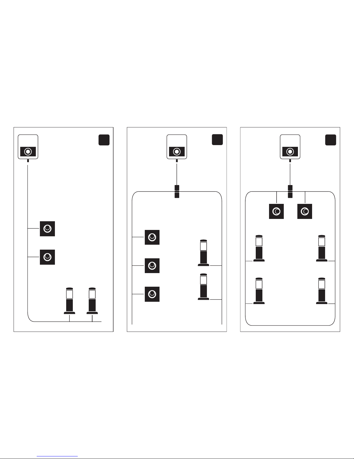
A En ligne
Le câble est déroulé et raccordé
au transformateur.
14/2 jusqu’à 40 mètres/131 pieds
10/2 jusqu’à 80 mètres/262 pieds
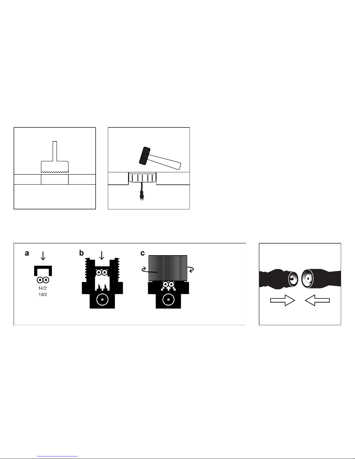
B Scindé
On peut couper le câble en deux
et réunir les deux parties à l’aide
d’un raccord de câble (CC-2).
14/2 jusqu’à 40 mètres/131 pieds
10/2 jusqu’à 80 mètres/262 pieds
C En boucle
Pour une longueur de câble 14/2
de plus de 40 mètres/131 pieds
et une longueur de câble 10/2 de
plus de 80 mètres/262 pieds, il
est conseillé de poser un
câblage en boucle. Il veille à
une alimentation électrique des
deux côtés et évite toute perte
de courant inutile. Résultat : un
rendement lumineux optimal.
Lors de l’utilisation d’armatures
à faible absorption de puissance,
l’effet de « perte de rendement
lumineux » surviendra moins
rapidement que pour les
armatures à absorption de
puissance élevée.
L’extrémité du câble est ramenée
et raccordée au câble le plus
près possible du transformateur.
Attention : veillez à raccorder les
mêmes côtés de câble, cannelés
ou lisses.
Longueur de câble
14/2 jusqu’à ± 60 mètres/
197 pieds
Longueur de câble
10/2 jusqu’à 160 mètres/
525 pieds*
*Plan lumineux avec spot de
50 W non compris.
Les câbles d’alimentation 14/2 et
10/2 supportent jusqu’à 250 W.
Optionen für die Verlegung des
12-Volt-Kabels
A Linear
Das Kabel wird ausgerollt und
an den Transformator ange-
schlossen.
14/2 bis 40 Meter
10/2 bis 80 Meter
B Geteilt
Das Kabel kann in zwei Teile
geschnitten werden, die an-
schließend mit einem Kabelver-
binder (CC-2) wieder miteinander
verbunden werden.
14/2 bis 40 Meter
10/2 bis 80 Meter
C Ringförmig
Bei 14/2-Kabeln ab 40 Meter
und 10/2-Kabeln ab 80 Meter
empehlt es sich, eine so
genannte Ringleitung anzulegen.
Sie sorgt für eine beiderseitige
Stromversorgung und verhindert
unnötige Stromverluste. Dadurch
gewährleistet sie eine optimale
Lichtausbeute.
Bei Verwendung von Armaturen
mit einer niedrigen Leistungsauf-
nahme wird der Effekt eines Ver-
lusts an Lichtausbeute geringer
ausfallen als bei Armaturen mit
hoher Leistungsaufnahme.
Das Ende des Kabels wird zu-
rückgeführt und möglichst nahe
beim Transformator wieder
an das Kabel angeschlossen.
Achten Sie darauf, dass Sie
immer dieselben Kabelseiten
(geriffelt oder glatt) miteinander
verbinden.
Kabellänge
14/2 bis ca. 60 Meter
Kabellänge
10/2 bis 160 Meter*
*Gilt nicht für Lichtpläne mit
50-W-Spot.
Die 14/2- und 10/2-Netzkabel sind
bis 250 W belastbar.
D F