P-Q Controls 504 Series User manual
P
-
Q Controls, Inc.
Doc. No:
504Manual.Doc
Phone (860) 583-6994 95 Dolphin
Road
Rev:
F
Date:
10/24/13
Fax (860) 583-6011 Bristol, CT, 06010
Author:
CAM
Page:
1 of 5
OPERATIONS MANUAL
MODEL 504 / 514 / 524 / 534
Property of P-Q Controls, Inc. www.p-qcontrols.com
Features
♦Independent Low Current Adjustment
♦Independent Mid Current Adjustment
♦Independent Hi Current Adjustment
♦Adjustable RAMP
♦Adjustable PWM Frequency
♦Dual Output Range (Mid/Hi)
♦Swap Feature
♦RAMP Duration Between MID and HI Ranges
♦Current Sourcing w/Feedback Outputs
♦2.5 Amp FET On/Off Outputs
♦Over-Signal Protection
♦Short Circuit Protection
♦Reverse Polarity Protection
♦Voltage Supply Transient Protection
♦EMI and RFI Resistant
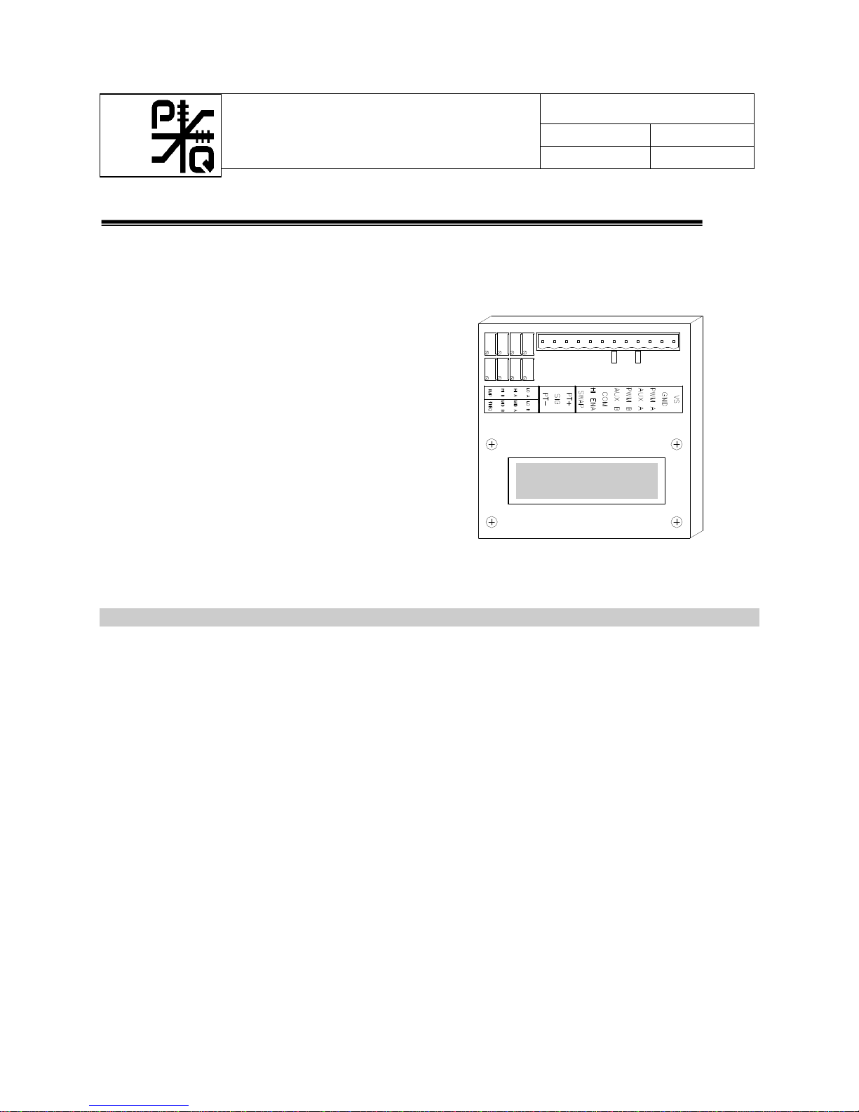
Description
The Model 504 series of valve drive boards are an electronic interface between a command source
(potentiometer, joystick, footpedal, etc.) and an electro-hydraulic valve or pump. The board receives
analog signals from the command source, and provides Pulse Width Modulated Output (PWM) to drive
most electrically modulated valves and pumps available today. The board also provides On/Off Outputs
and other features to smoothly stroke a valve or pump with greater control and flexibility over
conventional hydraulic components. The 504 family of valve drive boards are designed for use on mobile
equipment where extreme environments (both weather and electrical) are encountered. The boards also
offer features used in many industrial applications. The 504 board can be mounted directly to P-Q single
axis joysticks or can be remotely mounted up to 100 feet from the command source.
Output from the proportional channels is Pulse Width Modulated (PWM) with current monitoring. The
Model 504 boards can be configured to drive single coil, dual coil, single coil (flow control) grounded
coil valves, or single coil floating valves. The proportional current output will remain fixed within 2%
during supply voltage swings, and coil resistance changes, (which occurs as the valve coil temperature
rises). Light emitting diodes (LED’s) are lit whenever the command signal exceeds the board’s deadband
and the board begins to output. Should any of the outputs (digital or proportional) be shorted, the outputs
will automatically shut down.
504

OPERATIONS MANUAL
MODEL 504 / 514 / 524 /534
Page 2 of 5
504Manual.Doc
In addition to the proportional outputs, On/Off (digital) outputs are available to energize dump valves,
blocking valves, brakes, buzzers, etc. These solid state auxiliary outputs utilize field effect transistors
(FET’s) to provide continuous loads up to 2.5 Amps.
During the final phase of the automated testing, the adjustable parameters of the board are calibrated to
specifications published by the valve manufacturer. 25 turn trimpots are provided on the board to make
small adjustments to “fine tune” the output. Larger adjustments can also be made to drive valves other
than originally intended.
Ordering Information
Example Model 5 0 4 C 5 N R C S 3 - XXX
CALIBRATION NUMBER
BASE CONFIGURATIONS
504 - [180-2500mA 45-450Hz]
514 - [180-2500mA 451-1000Hz]
524 - [10-800mA 45-450Hz]
534 - [10-800mA 451-1000Hz]
MID RANGE
N – No Mid Range or Swap
C– Swap w/Common Mid Adjust
S– Swap w/Separate Mid Adjust
COMMAND SOURCE VS
5– 5VDC Regulated
6– 6VDC Regulated
OUTPUT CONFIGURATIONS
1– PWM A & PWM B
2– PWM A&B, Aux A&B
3– PWM A&B, Com Aux
4– PWM A&B, Aux A&B, Com Aux
5 - PWMA, Aux A&B, Com Aux
(Flow Control Arrangement)
6– PWM A&B, Aux A&B, Com Aux
(Floating connection)
LOW RANGE
C– Common LO Trimpot Adjust
S– Separate LO Trimpot Adjust
R– Range Dependent LO
Adjusts
HI RANGE
C– Common HI Trimpot Adjust
S– Separate HI Trimpot Adjust
RAMP FEATURE
N– No Ramp
R– Ramp Feature (0-5 Second Adj.)
C– Ramp Cancel
INTERNAL RESISTORS
N– No On-board Resistors
1– 180ΩPadding Resistors
2– 360ΩPadding Resistors
3– 18ΩPadding Resistors

OPERATIONS MANUAL
MODEL 504 / 514 / 524 /534
Page 3 of 5
504Manual.Doc
Operational Considerations
Voltage Supply: The board is capable of functioning properly when supplied with a DC voltage ranging
from 10-30 volts. To ensure proper operation, the DC ripple should be limited to less than 15% of the
supply voltage. Remember that the board can source as much as 8.5 amps through the voltage supply
with three outputs (PWM, common and directional auxiliary) active. The power supply wiring should be
sized appropriately to handle the maximum current draw anticipated.
Command Source: The 504 boards are generally driven with a 500ohm potentiometer with 180 ohm
padding resistors. The 180 ohm resistors attached to each leg of the potentiometer limit the voltage swing
of the command source. By limiting the voltage swing, the 504 board can detect problems associated
with the command source wiring (such as opens or short circuits). The 504 board will detect a problem
with the wiring and automatically shut down all outputs. With P-Q Inductively Coupled and Hall Effect
products, the “padding resistors” are built into the circuitry.
The voltage supply for the command source is provided by the PT+ and PT- terminals of the 504 board.
This voltage source is adequate to power single and multi-axis joysticks, footpedals, sensors, etc. An
external signal source with the proper signal swing can also be used to drive the 504 board.
PWM Outputs: The PWM outputs are current sourcing outputs. The outputs are implemented as a high
current F.E.T. switch connected to the Voltage Supply. The PWM outputs have thermal type current
limiting circuitry to shut down the outputs in the event of a short circuit.
SWAP: The SWAP feature comes with the Mid Range option. When a 12V signal is connected to the
SWAP terminal the PWM A & PWM B outputs reverse direction.
Operating Frequency: The PWM (Pulse Width Modulation) frequency is adjusted at P-Q to the frequency
recommended by the valve manufacturer for the specific valve to be driven. Adjustments to the
frequency are generally not required except in experimental applications or if working with a different
valve than originally intended.
Ramp: Ramp is provided to smooth the PWM output due to abrupt changes of the command signal or
when switching between output ranges (i.e. switching between Mid and Hi ranges). Ramp will adjust the
output rate-of-change from threshold to max (accel) and from max to threshold (decel). For example,
throwing the command source from PWM A to PWM B quickly will cause the PWM output to ramp from
the Hi A setting down to the Lo A setting and then skip through the neutral area instantaneously and begin
ramping from Lo B to Hi B. Ramp is factory preset to Off (full CCW) for ease of fine tuning the PWM
outputs. Adjust the RMP trimpot clockwise to obtain desired accel/decel time.
NOTE: Since the circuitry has delay for both accelerating and decelerating a load, it is important to note
that the only means for stopping the output quickly will be with an external switch. The switch should
energize a dump or blocking valve, interrupt the command signal at the board, or disconnect the valve
coils from the board. See applications bulletin 940208J1.DWG for specific instructions.
Ramp Cancel: Non standard option which immediately shuts off the PWM outputs when the command
source enters the neutral area.
Lo (A or B): The PWM output level when signal swing just exceeds deadband setting (20% of full signal
swing or a change of ±.30VDC). Value is in milliamperes and can range from 1 to 2500mA.
Hi (A or B): The PWM output level when signal swing reaches full (±1.5VDC). MID is the default
PWM output if HI is not enabled. Value is in milliamperes and can range from 100 to 2500mA.
Mid (A or B): The PWM output level when signal swing reaches full (±1.5VDC). Value is in
milliamperes and can range from 100 to 2500mA. To operate in the HIGH range apply vehicle supply to
HI Enable terminal.

OPERATIONS MANUAL
MODEL 504 / 514 / 524 /534
Page 4 of 5
504Manual.Doc
PT- and PT+ : The PT+ and PT- terminals provide 5VDC or 6VDC for the command source (check your
specific part number). These terminals are intended to be connected to a 500 Ohm potentiometer with
180Ωpadding resistors connected to each end leg of the potentiometer (refer to drawing).
Auxiliary Outputs: The Auxiliary outputs are protected with a thermal shutdown technique. In the event
of a short circuit, the output will not reset to normal operation unless the short has been removed, and
either the power cycled or the joystick returns to neutral.
Fine Tuning
As received, the board is calibrated for a specific valve or pump. A calibration number is recorded on the
serial number tag. The calibration number identifies the configuration of the adjustable parameters. Use
the model number and calibration number to reorder.
To fine tune the valve operation, several adjustments are provided. These adjustment trimpots may adjust
both the “A” and “B” outputs with one trimpot, or may be adjusted by separate trimpots for more precise
tuning. The specific model number determines what trimpots are provided.
LO (Threshold): The LO should be adjusted first. LO adjusts the output when the board first comes on.
Move the command source to its "just on" position (observe that the LED just turns on). Adjust the LO
trimpot (CW to increase) to obtain slight motion of the function.
HI (Maximum): Adjusts the maximum output to achieve full flow of the valve or pump. Move the
command source to the max position (observe lighted LED). Adjust the HI trimpot (CW to increase) to
obtain maximum desired function speed. Adjust HI CCW to a point where speed just starts to drop; then
turn trimpot CW ½ turn to ensure full utility of the command signal swing and eliminate excess current
delivered to the valve.
MID (Optional): Adjusts the midrange output. Disconnect supply voltage from terminal "HI ENABLE"
to put board in midrange mode. Move command source to max position and adjust MID speed.
NOTE: When the MID circuitry is activated, the proportional current at turn on (LO) will be lower than
that when the HI range electronics are engaged. The drop in current becomes greater as the difference
between the Mid calibration and the HI calibration become greater. The net result is that the operator will
need to move the control handle a little further in order to obtain a low function speed when in the
midrange mode. Choose the Range Dependent LO option to eliminate this occurrence.
RMP (Optional): Ramp is provided to smooth abrupt changes of the command signal. Ramp will adjust
the output duration from threshold to max (accel) and from max output to threshold (decel). Ramp is
factory preset to Off (full CCW) for ease of fine tuning LO and HI. Adjust the RMP trimpot (CW to
increase) to obtain desired accel/decel time.
NOTE: Since the circuitry has delay for both accelerating and decelerating a load, it is important to note
that the only means for stopping the output quickly will be with a switch. The switch should interrupt the
command signal or voltage supply to the board, disconnect the valve coil(s) from the board, or energize a
dump or blocking valve. See applications bulletin 940208J1.DWG for specific instructions.

OPERATIONS MANUAL
MODEL 504 / 514 / 524 /534
Page 5 of 5
504Manual.Doc
This manual suits for next models
4
Table of contents


