P1PE P5200MT User manual

1
FOR YOUR SAFETY
You must read and understand
this manual before use.
Keep this manual for future reference.

2
CONTENTS
PAGE NO.S
1
SAFETY
3 - 7
2
MACHINE SPECIFIC SAFETY
7 - 9
3
PART LOCATIONS
10
4
ASSEMBLY
11 - 15
5
FUEL & OIL
16 - 17
6
STARTING PROCEDURE
17 - 21
7
STOPPING PROCEDURE
21
8
OPERATING INSTRUCTIONS
22 - 26
9
MAINTENANCE
27 - 34
10
STORAGE & TRANSPORTING
34 - 35
11
TROUBLESHOOTING
36
12
DECLARATION OF CONFORMITY
37
13
RECYCLING
38
14
MANUAL UPDATES
39
15
WARRANTY
39
16
CONTACT DETAILS
39
INDEX

3
1. SAFETY
1.1
General Safety Notes.
1.2
The operator of the machine is responsible for,and has a duty of care in making sure
that the machine is operated safely and in accordance with the instructions in this
user manual. Keep the manual safe and pass it on if the machine is loaned or soldto
another user.
1.3
Please note the following safety points.
1.4
The machine should never be left it in a condition which would allow an untrained or
unauthorised person/s to operate thismachine.
1.5
All due care and diligence should be taken by the operator for the safety of and with
regard to those around whilst using the machine.
1.6
Some or all of the following - warning signs, symbols and/or PPE pictograms may
appear throughout this manual. You MUST adhere to their warnings. Failure to do
so may result in personal injury to yourself or those aroundyou.
DANGER
Indicates a hazard, which, if not avoided, could result in serious injury or death.
WARNING
Indicates a hazard, which, if not avoided, could result in serious injury.
CAUTION
Indicates a hazard which, if not avoided, might result in minor or moderate injury.
NOTE
Indicates a situation that could easily result in equipment damage.
READ and keep the manual safe and pass it on if the machine is loaned or sold to another user.
You MUST fully understand all instructions to ensure you use and operate the machine safely.
Appropriate Personal Protective Equipment (PPE), MUST be worn at all times when operating or
repairing the machine.

4
1.10
Carbon Monoxide (where applicable).
1.11
Carbon monoxide is a colourless and odourless gas. Inhaling this gas can cause
death as well as serious long term health problems such as braindamage.
1.12
The symptoms of carbon monoxide poisoning can include but are not limited to the
following;
Headaches, dizziness, nausea, breathlessness, collapsing or loss of consciousness.
1.13
Carbon monoxide poisoning symptoms are similar to flue, food poisoning, viral
infections and simply tiredness. It is quite common for people to mistake this very
dangerous poisoning for something else.
1.14
To avoid carbon monoxide poisoning DO NOT use Petrol/Diesel powered equipment
inside any of the following; Home, garage, tent, camper van, mobile home, caravan
or boat. This is not exhaustive and if you are in any doubt contact yourdealer.
1.15
If you think you have or someone around you has been affected by carbon monoxide
poisoning;
1.16
Get them fresh air immediately, by leaving the affected area or by opening doors and
windows. If safe and practical to do so make sure that the machine is turned off.
DO NOT enter a room you suspect of having carbon monoxide present –instead call
the emergency services.
1.17
Contact a Doctor immediately or go to Hospital –let them know that you suspect
carbon monoxide poisoning.
1.18
DO NOT use in an enclosed area or moving vehicle.
1.20
General Fuel Safety (where applicable).
CAUTION
ALL FUELS ARE FLAMABLE
1.21
Fire Hazard –keep fuel away from all sources of ignition for example heaters.
Lamps, sparks from grinding or welding.
1.22
DO NOT carry out hot work on tanks that have contained fuel.
1.23
ALWAYS keep the work area tidy.

5
1.24
ALWAYS clean up spills promptly using absorbent granules and a lidded bin.
1.25
ALWAYS dispose of waste fuels correctly.
1.30
Fueling/De-fueling (where applicable).
CAUTION
ALL FUELS ARE FLAMABLE
1.31
ALWAYS fuel and defuel in a well ventilated area outside of buildings.
1.32
ALWAYS wear correct, suitable and fit for purpose Personal Protective Equipment
(PPE), suggested items are but not limited to safety gloves, overalls.
1.33
When fueling/de-fueling ALWAYS avoid inhaling fumes.
1.34
When de-fueling ALWAYS use a proper fuel retriever.
1.35
ALWAYS carry fuel in the correct and clearly marked container.
1.40
Electrical Safety )where applicable).
1.41
Electricity can kill –NEVER work on LIVE/ENERGISED equipment.
1.42
Prior to carrying out any maintenance work you MUST identify electrical isolation
methods and isolate all electrical supplies.
1.43
Prior to use and with all electrical supplies isolated, you MUST check all electrical
cables, plugs and connectors for the following;
1.44
Are intact and have no signs of damage, to include but not limited to bare wires,
chaffing, cuts and loose wiring.
1.45
If there are any signs of damage, the damage item MUST be taken out of service
until the damage has been repaired by an electrically competent person.
1.46
All trailing cables should be routed so as not to cause any kind of triphazard.
1.47
NEVER work on or near electricity with wet hands, wet clothing and wetgloves.

6
1.50
Batteries (where present).
1.51
Batteries present a risk if they become damaged by the possible leaking of
electrolyte. This electrolyte is an acid and can cause serious burn injuries. Care
should be taken when working on or near them. NOTE the electrolyte may be in
a liquid or gel form.
1.52
Should you come in to contact with electrolyte you should;
1.53
Remove all clothing contaminated with electrolyte. If you cannot remove then
saturate them in water.
1.54
Get medical assistance as soon as possible. You must advise the medical staff of
the type of acid.
1.55
Lead/acid battery = dilute sulphuric acid.
1.56
Nickel/cadmium = potassium hydroxide alkali electrolyte.
1.57
Use fresh running water to wash off excess electrolyte, continue this until medical
assistance arrives. Make sure that you do not was the electrolyte to another part of
your body or face.
1.58
If electrolyte comes in to contact with Eyes the electrolyte needs to be immediately
washed away with large amounts of water. Make sure that you do not wash the
electrolyte to another part of your face or body.
1.59
Gasses from charging batteries are highly flammable and great care should be taken
to charge in well ventilated areas.
1.59.1 There is an explosion risk if the battery terminals are short circuited, when
connecting/disconnecting ALWAYS exercise great care so that the terminals or
battery leads are NOT allowed to touch and cause a spark. ALWAYS use suitable
insulated tools.
1.60
Vibrations (where applicable).
1.61
Prolonged use of hand held (operated) machines will cause the user to feel the
effects of/from vibrations. These vibrations can lead to white finger (Raynaud’s
phenomenon) or carpal tunnel syndrome. This condition reduces the ability of the
hand to feel and regulate temperature, causing numbness and heat sensations and
may cause never damage and circulatory tissue death.
1.62
Not all factors that lead to white finger disease are known, but cold weather, smoking
and other diseases that affect blood vessels and blood circulation as well as large
and long-lasting impact of shocks are considered factors in the formation of white
finger. Note the following to reduce the risk of white finger and carpal tunnel
syndrome;
1.63
Wear gloves and keep your hands warm.
1.64
Take regular breaks.
1.65
All of the above precautions may help reduce the risk of white finger disease but not
rule out the carpal tunnel syndrome. Long-term and regular users are therefore
recommended to observe the condition of your hands and fingers. Seek medical
attention immediately if any of the above symptoms should occur.
1.70
Noise (where applicable).

7
1.71
The operating noise of the machine can damage your hearing. Wear hearing
protection such as earplugs or ear defenders to protect your hearing. Long-term
and regular users are advised to have hearing checked regularly. Be especially
vigilant and cautious when hearing ear protection because your ability to hear alarm
warnings will be reduced.
1.72
Noise emissions for this equipment is unavoidable. Carry out noisy work at approved
times and for certain periods. Limit the working time to a minimum. For your personal
protection and protection of people working nearby it is also advisable for them to
wear hearing protection.
1.73
See CERTIFICATE of CONFORMITY section for Outdoor Noise declaration of
conformity.
2. MACHINE SPECIFIC SAFETY
CAUTION
This machine may ONLY be used for trimming grass, weeds and brushwood.
Never use for other purposes as this may result in serious injury.
Safety instructions MUST be observed.
DO NOT expose yourself or others to the risks.
2.0
Always wear safety goggles for eye protection.
2.1
Long hair must be tied back.
2.2
Do not wear loose clothing or jewellery that could get caught in movingparts.
2.3
Safe, strong non-slip safety shoes must be worn.
2.4
It is recommended that legs and feet are fully protected.
2.5
Check the entire machine for loose or missing parts, repair or replace asnecessary.
2.6
Check all nuts, bolts and screws to ensure they are tight.
2.7
ONLY use parts and accessories recommended by the manufacturer.
2.8
Keep the handles free of oil, grease and fuel.
2.9
Always use the shoulder strap.
2.10
DO NOT smoke when mixing fuel or when filling the tank.
2.11
DO NOT mix fuel in an enclosed area or near ignition sources.
ALWAYS handle fuel with care in a well ventilated area.
2.12
Never remove the fuel filler cap while the engine is running.
2.13
DO NOT operate the machine in enclosed spaces or buildings.
Exhaust gasses contain Carbon Monoxide which can kill.
2.14
Do not run whilst using the machine.

8
2.15
NEVER make adjustments or repairs with the machine running.
2.16
DO NOT use the machine if it is damaged.
2.17
NEVER remove any of the safety devices on this machine.
2.18
Check the area before use to ensure it is clear of any obstructions, cables or
obstacles that may cause damage to the cutting heads.
2.19
NEVER leave the machine unattended.
2.20
Maintain a proper footing when using the machine. DO NOT use the machine while
standing on a ladder or any other unstable surface.
2.21
Keep all other persons or animals at least 15m from the work area.
2.22
Keep hands and feet away from the cutting heads during operation.
2.23
DO NOT use the machine if you are tired, ill or under the influence of medication,
drugs or alcohol.
2.24
If you strike and obstacle, stop the engine and check the cutting head. Repair or
replace as needed.
2.25
Before starting, after failure or impact, make sure to check the machine is in good
condition.
2.26
Improper maintenance, the use of non-compliant spare parts or the removal of safety
devices can result in damage to the unit and serious injury to the operator.
2.27
Secure the unit during transport to prevent fuel loss, damage to the unit or injury.
Always install the protective part of the cutting blade before transportation.
2.28
On machines with a clutch, you must check regularly that the cutting accessory stops
rotating when the engine is idling.
2.29
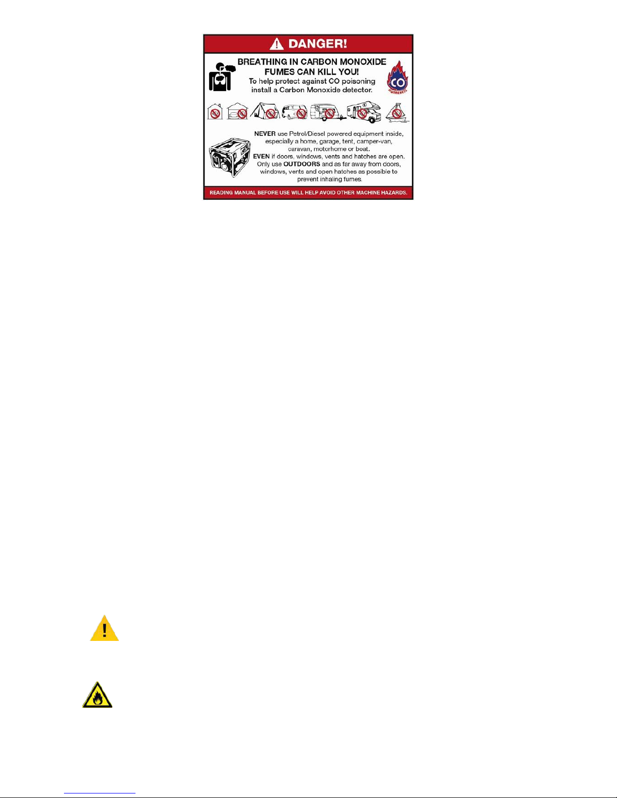
Do not store the machine in a closed area where fuel vapours may reach an open
flame or ignition source.
2.30
ALWAYS turn the machine off and allow to cool before carrying out any
maintenance, repairs or refuelling.
2.31
NEVER operate the pruner/hedge trimmer at an angle greater than 60°.
This will reduce the risk of being struck by falling objects duringoperation.
2.32
When you’ve finished cutting in one location and wish to continue working at another
location, turn off the engine, lift up the unit and carry it, paying close attention to the
blade.
2.33
Always cover the blades to prevent injury during transport.
2.34
When carrying, always cover the blades to avoid injury or damage.
2.35
Never transport the machine over rough ground or long distances by vehicle without
removing all fuel from the fuel tank.
2.36
Kickback may occur when the nose or tip of the guide bar touches an object or when
the wood closes in and pinches the saw chain in the cut.
Kickback or pinching may cause a fast reverse action, kicking the guide bar up and
back towards the operator.
Either of these reactions may cause you to lose control of the saw, which could
result in serious personal injury.

9
2.37
Do not rely exclusively on the safety devices built in to your saw.
As a chain saw user you should take several steps to keep cutting jobs free from
accident or injury.
2.38
With a basic understanding of kick-back you can reduce the element of surprise.
2.39
Keep a good grip on the saw with both hands.
The right hand on the rear handle and the left hand on the front handle when the
engine is running.
Use a firm grip with thumbs and fingers encircling the chain saw handles.
2.40
A firm grip will help you reduce kick back and maintain control of the saw.
2.41
Make certain that the area in which you are cutting is free from obstructions.
Do not let the nose of the guide bar contact a log, branch or any other obstruction.
2.42
Follow the manufacturers sharpening and maintenance instructions for the saw
chain.
2.43
Only use replacement bars and chains specified by the manufacturer orequivalent.
WARNING
ALWAYS make sure the chain and sprocket are correctly adjusted before operating
the pruner.
DO NOT attempt chain adjustment while the engine is running.
2.44
NEVER use a cracked or warped guide bar.
Replace it with a serviceable one and make sure it fits properly.
2.45
If a saw blade should be fast in a cut, shut off the engine immediately.
Push the branch or tree to ease the bind and free the blade.
2.46
DO NOT operate the pole pruner with the muffler removed.
2.47
When cutting a limb that is under tension, be alert for spring back so that you will not
get struck by a moving limb.
2.48
Always stop the engine and check immediately for damage if you strike a foreign
object or if the machine becomes tangled.
2.49
DO NOT operate with broken or damaged equipment.
2.50
DO NOT make modifications or substitutions to the machine.
2.51
NEVER allow the engine to run at high RPM without a load.
Doing so could damage the engine.

10
3. PART LOCATIONS
1
Loop Handle
13
Choke Lever
2
Suspension Point
14
Air Filter Cover
3
Stop Switch
15
Cutting Attachment Guard
4
Throttle Cable
16
Angle Transmission
5
Throttle Trigger
17
Cutting Line Head
6
Throttle Set Button
18
Blade
7
Main Drive Shaft
19
Transmission
8
Shaft Bolt
20
Guide Bar
9
Spark Arrester
21
Saw Chain
10
Starter Knob
22
Chain Cover
11
Fuel Tank
23
Transmission
12
Primer Bulb

11
4. ASSEMBLY
CAUTION
For OUTDOOR use ONLY.
Petrol machinery produces carbon monoxide –a poisonous, colourless and
odourless gas that can cause serious injury or death. Petrol is highly flammable,
always handle with extreme care and in a well ventilated area.
NOTE
Images may vary depending on model.
3.0
Mount the handle (1) to the main drive shaft (2) using the screws provided.
3.1
Do not fully tighten the screws until you have found a comfortable workingposition.
3.2
Once a comfortable working position has been found, tighten the screws
securely.
(1)
Front Handle
(2)
Main Drive Shaft
3.3
To connect an attachment to the drive shaft.
3.4
Press the lever (1) on the drive shaft.
3.5
Slide the attachment into the drive shaft ensuring it is fully engaged.
Premature wear can take place if the connector is not tightenedproperly.
3.6
Locate the locking hole (2) and release the lever.
3.7
Tighten the locking knob (3) in a clockwise direction.

12
(2) Locking Hole
(3)
Locking Knob (1) Lever
INSTALLING THE BRUSH CUTTER
3.15
Fix the cutting guard (1) to the shaft (2) using the screws (3) provided.
(2)
Shaft
(1)
Cutting Guard
(3)
Screws
3.16
Insert the allen key provided (1) into the gear case locking hole to prevent the shaft
from rotating.
3.17
Secure the metal blade onto the gearbox head (2) making sure it is centrally located
on the collar with the text on the blade facing upwards.
3.18
Insert the lower washer (3) and the cover (4).
3.19
Hold the allen key (1) firmly in the gear case locking hole and tighten the nut
(5) securely, with the box spanner provided.
(5) Nut
(2)
Gear Case Locking Hole (4) Cover
(3)
Lower Washer
(1)
Allen Key (3) Gearbox Shaft

13
INSTALLING THE GRASS TRIMMER
3.20
Insert the allen key provided (1) into the gear case locking hole to prevent the shaft
from rotating.
3.21
Screw the nylon spool (2) onto the shaft thread if the spool is threaded.
If the spool does not have a threaded centre hole, use the nylon nut and tighten
securely (you will have to remove the spool from spool housing).
3.22
Check the spool is secured tightly.
(2)
Gear Case Locking Hole
(1)
Allen Key
INSTALLING THE HEDGE TRIMMER
3.23
Insert the end of the hedge trimmer mechanism (1) into the end of the main shaft(2).
3.24
Line up the hole on the end of the main shaft (3) with the hole in the end of the
hedge trimmer mechanism (4).
3.25
With both holes lined up, insert the fixing screw (5) and tighten securely.
(2)
Main Shaft
(3)
Shaft Hole
(4)
Trimmer Hole
(5)
Fixing Screw (1) Trimmer Mechanism

14
(1) Lever
3.26
To adjust the angle of the hedge trimmer blade, stop the engine.
3.27
Turn the lever (1) anti-clockwise.
3.28
Adjust the angle of the blades and tighten the lever clockwise to secure.
INSTALLING THE PRUNER
WARNING
The saw chain has very sharp edges. For safety you MUST wear protective gloves.
WARNING
Pay attention to the correct direction of the saw chain.
WARNING
It is very important to maintain proper chain tension.
Rapid wear of the guide bar or the chain coming off can be caused by improper
tension.
CAUTION
When using a new chain, take great care to check adjustment.
A new chain will stretch when first used.

15
3.29
Loosen the cover nut (1) and remove the chain cover (2).
3.30
Mount the guide bar (3) and loop the saw chain (4) around the bar and sprocket(5).
(3)
Guide Bar (4) Saw Chain (5) Sprocket
(1)
Chain Cover Nut (2) Chain Cover
3.31
Fit the chain tensioner nut (1) into the lower hole of the guide bar.
Then install the chain cover, fasten the nut to finger tightness.
(1)
Chain Tensioner Nut (2) Chain Cover
3.32
While holding the tip of the bar, adjust the chain tension by turning the tensioner
screw (1) until the tie straps on the chain just touch the bottom side of the guide bar
rail.
3.33
Tighten the chain cover nut (2) securely with the bar tip held up.
Then check the chain for smooth rotation and proper tension by moving it by hand.
If necessary, re-adjust with the chain cover loose.
(2)
Chain Cover Nut
(1)
Tensioner Screw

16
(1) Oil Filler Cap
5. FUEL AND OIL
WARNING
All fuels are flammable and must be handled and stored correctly.
Always ensure there is adequate ventilation when handling fuels.
NOTE
This machine is equipped with a two stroke engine and must always be run using a
mixture of petrol and two stroke oil. It is important to accurately measure the amount
of oil to be mixed to ensure the correct mixture is obtained.
4.0
Mix fresh unleaded petrol with a good quality semi-synthetic 2 stroke engine oil to a
ratio of 40:1.
40 parts Unleaded Petrol
1 part Semi-Synthetic 2 Stroke Oil
1 litre
25ml
2 litres
50ml
3 litres
75ml
4 litres
100ml
5 litres
125ml
4.1
Clean the area around the fuel cap before removal.
4.2
Position the machine so the fuel cap is facing upwards.
4.3
Fill the fuel tank with the correct 40:1 mix of unleaded petrol and semi-synthetic 2
stroke engine oil.
4.4
DO NOT overfill, leave a 25mm gap at the top of the fuel tank.
CHAIN OIL
4.4
Use a good quality chainsaw chain oil.
4.5
Place the unit on its side and remove the oil filler cap (1).
4.6
Fill with chain oil to the correct level.
4.7
Securely replace the oil filler cap
4.8
Do not over fill the chain oil tank and wipe up spills immediately.

17
4.9
After starting the engine (see section 5) run the chain at medium speed and see if
the chain oil has scattered off as shown in the image below.
6. STARTING PROCEDURE
NOTE
This machine is shipped without fuel/oil mix. Therefore you MUST fill the engine with
the correct fuel/oil mix before operation.
Failure to do so will result in engine damage which will not be covered by warranty.
Fill with a 40:1 ratio of semi-synthetic 2 stroke oil and fresh unleaded petrol.
See section 5 for further information.
FROM COLD
5.0
Fill the fuel tank (1) with the correct 40:1 mix of unleaded petrol and semi-synthetic 2
stroke engine oil.
5.1
DO NOT overfill, leave a 25mm gap at the top of the fuel tank.
(1)
Fuel Tank
5.2
Rest the machine on flat, lever ground.
Keep the cutting head off the ground and clear of surrounding objects as it will start
rotating on start up.

18
5.3
Push the primer bulb (1) 6 times or until you can see fuel in the clear pipe.
(1)
Primer Bulb
5.4
Move the choke lever (1) to the closedposition.
(1) (2)
(3)
(1)
Choke Lever (2) Close (3)
Open
5.5
Place the unit on flat level ground.
Move the stop switch to the Run/Start position.
Set the throttle trigger to the start position.
Pull the throttle lever back and push.
Keep the cutting head clear of everything around it.
(1)
(3)
(2)
(4)
(1) Run / Start (2) Stop (3) Start Lever (4) Throttle Lever
5.6
While holding the unit firmly, pull the starter rope gently until you feel resistance, then
pull swiftly until the engine tries to fire.
NOTEThis machine is fitted with an easy recoil start assembly which allows it
to be started with less force and a more gentle pulling action.
I
O

19
WARNING
This machine is equipped with a centrifugal clutch, so the cutting attachment will
start to rotate as soon as the engine has started.
When starting, place the machine on flat, clear ground to ensure the cutting head
does not come in to contact with any obstacles.
5.7
Once the engine has attempted to fire, move the choke lever downwards to open the
choke and restart the engine.
5.8
If the engine does not start under full choke, move the choke lever down to the open
position.
5.9
Pull the recoil starting handle swiftly until the engine runs.
5.10
Allow the engine to warm up for several minutes before operation.
FROM WARM
5.11
Place the unit on flat level ground.
Move the stop switch to the Run/Start position.
Set the throttle trigger to the start position.
Pull the throttle lever back and push.
Keep the cutting head clear of everything around it.
5.12
While holding the unit firmly, pull the starter rope gently until you feel resistance, then
pull swiftly until the engine fires.

20
ADJUSTING THE THROTTLE CABLE
NOTE
You must only make adjustments after the engine has had time to warm up.
5.14
The normal amount of play is 1 to 2mm when measured at the carburetor end.
5.15
If the cable requires adjustment, remove the air filter housing to expose the
adjustment screw.
5.16
Loosen the lock nut.
5.17
Wind out the threaded cable adjuster until the desired tension is reached.
5.18
Tighten the lock nut back up securely.
(3) Lock Nut
(1)
Air Filter Housing (2) Threaded Cable Adjuste
Other manuals for P5200MT
1
Table of contents
Other P1PE Lawn And Garden Equipment manuals
Popular Lawn And Garden Equipment manuals by other brands

FLORABEST
FLORABEST GB-2784 Instructions for use

Little Giant
Little Giant DFB Series owner's manual

Zest 4 Leisure
Zest 4 Leisure Windsor Cascade Planter Assembly instructions

Factoryfurniture
Factoryfurniture Circular Operation & maintenance manual

Yard Works
Yard Works 2-outlet Water Timerwith Digital Display Quick manual

N'oveen
N'oveen IKN863 user manual