HOIST AND WIRE ROPE
INSTALLATION
1. The hoist should be mounted with the centerline of
the cable drum in a horizontal position. The mounting
plane of the hoist may be rotated in any position
around this centerline providing the vent in the motor
adapter is above the centerline of the cable drum.
The vent should be as close to top dead center as
possible.
2. When mounting the hoist, use all four (4) mounting
holes and grade eight (8) bolts and nuts. Evenly tight-
en the nuts to the torque in the "Recommended
Torque" chart.
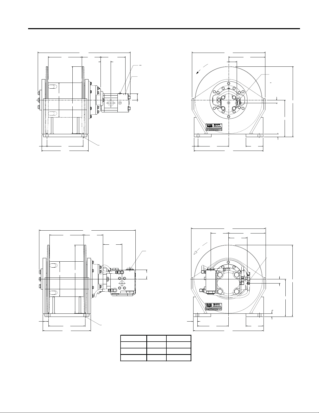
Refer to "Dimensional Drawing" for bolt hole size and pat-
tern.
The hoist must be mounted on a surface that will not flex
when the hoist is in use, and cause binding of the gear
train. Binding in the gear train will result in accelerated
wear and heat. Also, the mounting surface must be flat
with ± 0.020 in. (.5mm). If necessary, install shims under
the hoist mounting pads to achieve even mounting.
3. The hydraulic lines and components that operate the
hoist should be of adequate size to assure minimum
back pressure at the hoist. The back pressure at the
motor must not exceed 50 psi (345 kPa) to maintain
full system design braking and optimum motor seal
life.
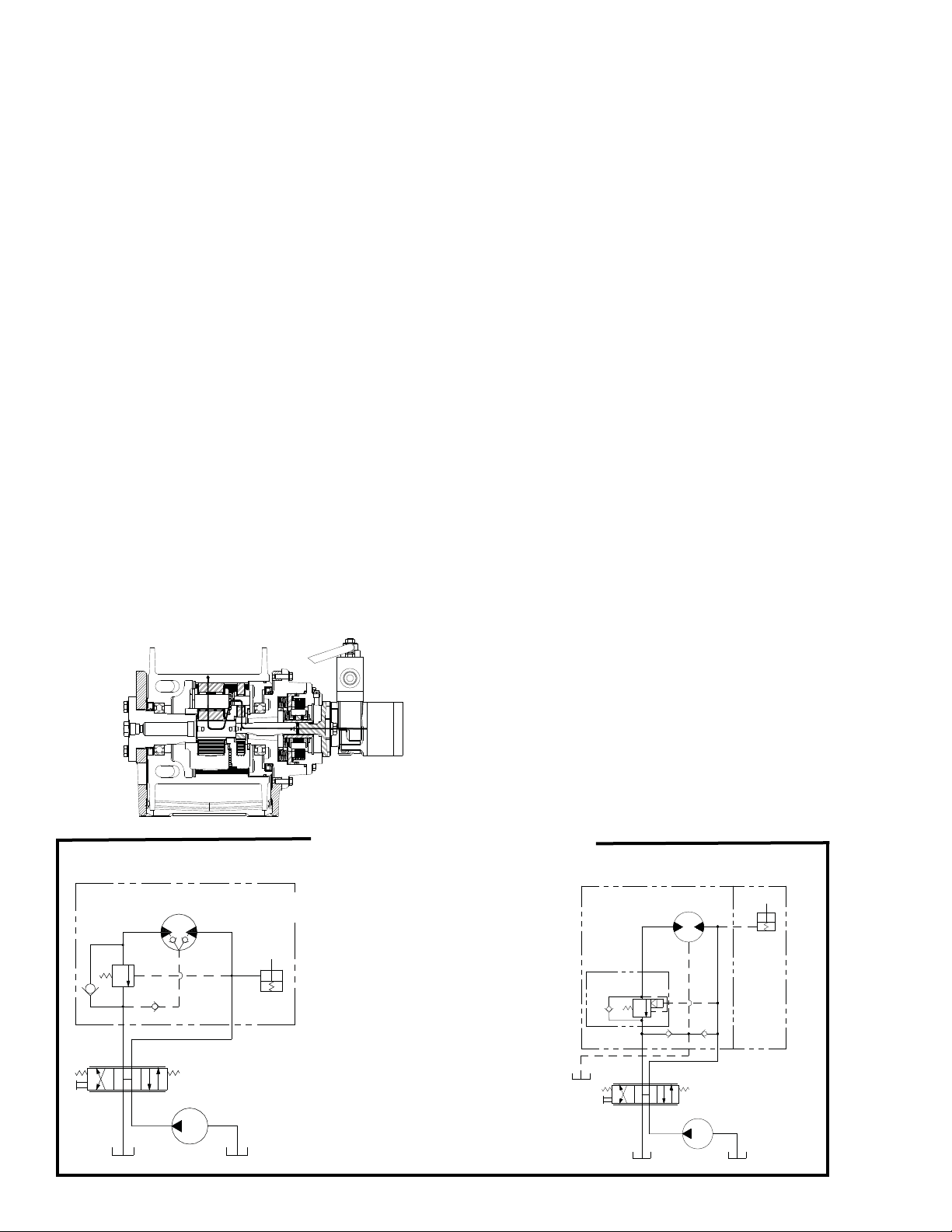
The hoist directional control valve must be a three position
four way valve with a motor spool such that when the
valve is in the center position both work ports are open to
tank (open center, open port).
4. High quality hydraulic oil is essential for satisfactory
performance and long hydraulic system component
life.
Oil having 150 to 330 SUS viscosity at 100oF (38oC) and
viscosity index of 100 or greater will give good results
under normal temperature conditions. The use of an oil
having a high viscosity index will minimize cold start trou-
ble and reduce the length of warm-up periods. A high vis-
cosity index will minimize changes in viscosity with corre-
sponding changes in temperature.
Maximum cold weather start-up viscosity should not
exceed 5,000 SUS with a pour point at least 20oF (-7oC)
lower than the minimum ambient temperature.
Under continuous operating conditions the temperature of
the oil at any point in the system must not exceed 180ºF
(82oC). 120oF (49oC) to 140oF (60oC) is generally consid-
ered optimum.
In general terms:
For continuous operation at ambient temperatures
between 50oF (10oC) and 110oF (43oC), use SAE 20W;
for continuous operation between 10oF (-12oC) and 90oF
(32oC), use 10W; for applications colder than 10oF (-
12oC), contact the BRADEN Service Department. The
use of multi-viscosity oils is generally not recommended.
5. The hydraulic oil filter should have a 10 micron nomi-
nal rating and be full flow type; or one in accordance
with recommendations of the pump manufacturer.
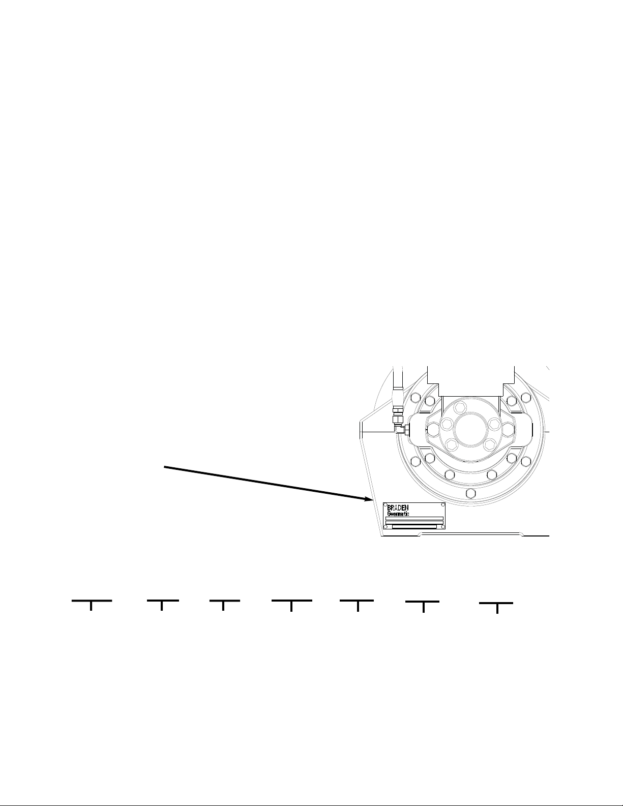
6. The vent plug in the motor adapter must be located
close to top dead center as possible. If the hoist is
mounted on a pivoting surface, the vent plug must
remain above the centerline of the cable drum to pre-
vent gear oil leakage.
7. Refer to "Dimensional Drawing" for relationship
between drum rotation and which port is pressurized.
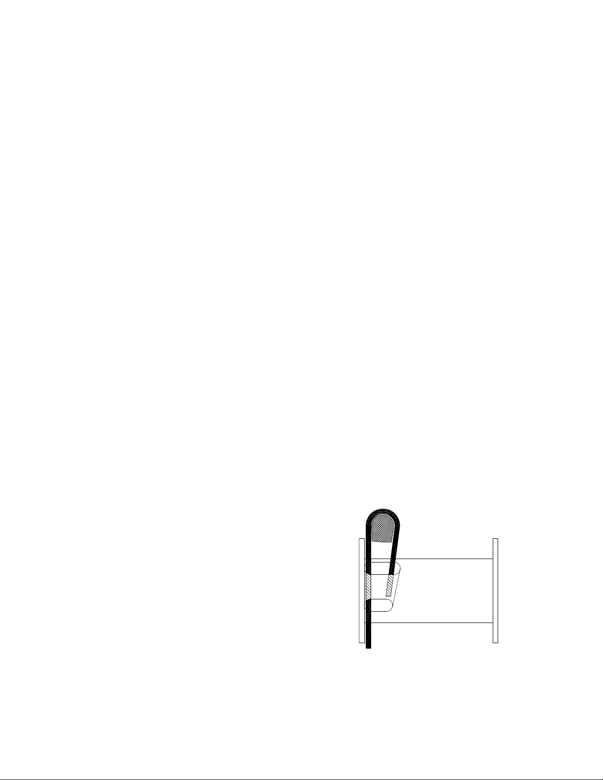
WIRE ROPE INSTALLATION
Since the static brake on this hoist is "effective both direc-
tions", cable can be wound onto the drum in either direc-
tion without any modifications to the hoist. The cable
drum has two anchor pockets to accommodate this. Take
the free end of the wire rope and insert it through the small
opening of the anchor pocket you are going to use. Loop
the wire rope and push the free end about three-fourths of
the way back through the pocket. Install the cable anchor
with the small end toward the drum, then pull the slack out
of the wire rope. The cable anchor will slip into the pock-
et and secure the wire rope to the drum. A minimum of
five (5) wraps of wire rope should remain on the cable
drum at all times. Refer to "General Safety
Recommendations" for additional information.
The standard cable anchor wedge supplied with the hoist
is intended for 5/16 to ½in. (8 to 13 mm) wire rope.
8