Pace DC900X User manual

MoCA LAN
DC900X
BRINGING TECHNOLOGY HOME
www.pace.com
INSTALLATION GUIDE
Pace DC900X for Home Content Sharing
RELEASE 30th Oct. 2009

2
DC900X INSTALLER’S MANUAL (501-3434310) RELEASE 30th Oct. 2009
CONTENTS
This manual describes some on-screen displays such as menus. These may change in the future, if the
software in the DC900X NAS or in the client set-tops is updated over the cable. However, the way that you use
the menus will remain similar to the way described in this manual.
SAFETY INFORMATION..................................................................................................3
IMPORTANT SAFETY INSTRUCTIONS....................................................................... 3
OVERVIEW.....................................................................................................................6
Front panel.................................................................................................................6
Rear panel .................................................................................................................6
BACKGROUND TO HOME CONTENT SHARINGTM ...................................................................................................... 7
Network-Attached Storage.........................................................................................7
MoCA networks .........................................................................................................7
MoCA-Ethernet hybrid network..................................................................................7
Ethernet-only network ...............................................................................................9
CONNECTING THE EQUIPMENT...................................................................................10
In-home connection scenario for MoCA-Ethernet hybrid network ...........................10
Using existing cabling..............................................................................................11
Deciding on the location for the NAS....................................................................... 11
Connecting an additional coax splitter ..................................................................... 11
Connecting up the NAS............................................................................................ 11
Connecting a low-pass filter at client set-top 3........................................................ 11
Connecting a low-pass filter at the POE................................................................... 11
Connecting up client set-tops 1 and 2 .....................................................................11
POWERING UP THE NETWORK AND SWITCHING ON/OFF..........................................12
Checking connections..............................................................................................12
Powering up the equipment in the correct order .....................................................12
Switching off the NAS.............................................................................................. 12
PREPARING FOR HOME CONTENT SHARING AT CLIENT SET-TOPS...........................13
Enabling Home Content Sharing at client set-tops...................................................13
Programming the remote control for Home Content Sharing .................................. 13
USING DIAGNOSTICS SCREENS TO CHECK THE NETWORK.......................................14
Noting the appropriate MAC addresses ...................................................................14
Displaying the Diagnostics Information screens......................................................14
Using the Diagnostics Information screens: ............................................................15
Relevant information on the DIAGNOSTICS DASHBOARD.......................................15
Using the MoCA Diagnostics screens......................................................................15
Using NAS Diagnostics............................................................................................ 18
Displaying the NAS Diagnostics screens .................................................................18
OTHER RELEVANT DIAGNOSTICS SCREENS...............................................................21
Using the HDD STATUS menu .................................................................................21
Using the DVR Status screen...................................................................................21
USING My Network TO CHECK THE INSTALLATION .................................................... 22
How My Network differs from My DVR....................................................................22
Recording some sample content .............................................................................22
Displaying the My Network screen ..........................................................................22

3
DC900X INSTALLER’S MANUAL (501-3434310) RELEASE 30th Oct. 2009
SAFETY INFORMATION
This Home Content SharingTM (HCS) server, often known as Network
Attached Storage (NAS), has been manufactured and tested with your
safety in mind. However, improper use can result in potential electric
shock or fire hazards. To avoid defeating the safeguards that have been
built into the NAS, please observe the precautions discussed in this
document.
Warnings
To reduce the risk of electric shock, do not remove the cover of the NAS.
There are no user-serviceable parts inside it.
Do not perform any servicing unless you are qualified to do so. Refer all
servicing to qualified service personnel. Servicing the NAS yourself will
invalidate the warranty.
To reduce the risk of fire or electric shock, do not expose this NAS to rain
or moisture.
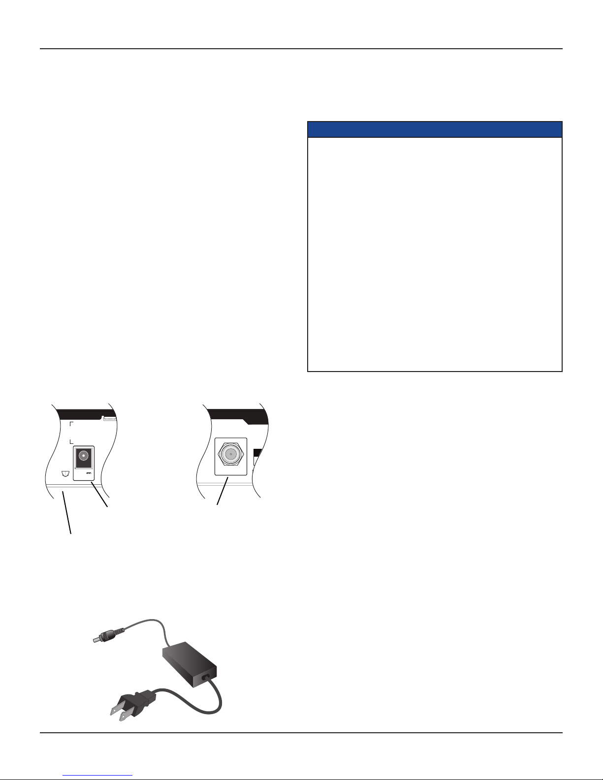
On the rear panel of the NAS there is a tamper-evident label that states
‘Warranty void if broken or removed’.
To avoid possible damage to the internal hard disk, do not pick up or move
the NAS while it is powered up. If you want to move the NAS, first stop any
recording, then turn off the NAS and wait 60 seconds before disconnecting
it from its power supply unit. You should handle the NAS carefully, as any
damage you cause to the internal hard disk (or any other component) will
invalidate the warranty.
Installation
The installation of the NAS should be carried out by a qualified installer
and should conform to local codes.
Note to the installer
This reminder is provided to call the attention of the cable-TV-system
installer to Section 820 of the National Electrical Code (USA), which
provides guidelines for proper grounding and, in particular, specifies
that the cable ground shall be connected to the grounding system of the
building, as close to the point of cable entry as is practical.
IMPORTANT SAFETY INSTRUCTIONS
Before you install or use the apparatus, you must read and
understand these Important Safety Instructions.
At all times when using the apparatus you must follow
these Important Safety Instructions to reduce the risk of fire,
electrical shock and injury to persons.
1. Read these instructions.
2. Keep these instructions.
3. Heed all warnings.
4. Follow all instructions.
5. Do not use this apparatus near water.
6. Clean only with dry cloth.
7. Do not block any ventilation openings. Install in accordance
with the manufacturer’s instructions.
8. Do not install near any heat sources such as radiators, heat
registers, stoves, or other apparatus (including amplifiers)
that produce heat.
9. Do not defeat the safety purpose of the polarized or grounding-
type plug. A polarized plug has two blades with one wider than
the other. A grounding type plug has two blades and a third
grounding prong. The wide blade or the third prong are provided
for your safety. If the provided plug does not fit into the outlet,
consult an electrician for replacement of the obsolete outlet.
10. Protect the power cord from being walked on or pinched
particularly at plugs, convenience receptacles, and the point
where they exit from the apparatus.
11. Only use attachments/accessories specified by the
manufacturer.
12. Use only with the cart, stand, tripod, bracket, or table specified
by the manufacturer, or sold with the apparatus. When a
cart is used, use caution when moving the cart/apparatus
combination to avoid injury from tip-over.
Service address:
Pace Americas Inc.
3701 FAU Boulevard, Suite 200, Boca Raton, Florida 33431 U.S.A.
13. Unplug this apparatus during lightning storms or when
unused for long periods of time.
14. Refer all servicing to qualified service personnel. Servicing
is required when the apparatus has been damaged in any
way, such as power-supply cord or plug is damaged, liquid
has been spilled or objects have fallen into the apparatus, the
apparatus has been exposed to rain or moisture, does not
operate normally, or has been dropped.
© 2009 Pace plc. All rights reserved.

4
DC900X INSTALLER’S MANUAL (501-3434310) RELEASE 30th Oct. 2009
SAFETY INFORMATION (cont.)
In addition to the Important Safety Instructions, please read the Safety
Information below.
Power sources
The model number, serial number, and electrical rating of this NAS are on
a label on its base.
You must operate the NAS only from the type of power source indicated
on the marking label. If you are not sure of the type of power supply to
your home, consult your dealer or local power company. If you move the
NAS between locations at different temperatures, allow it to reach room
temperature before you apply power to it.
Overloading
Do not overload wall AC outlets, extension cords or other power outlets as
this can result in a risk of fire or electric shock.
Lightning
For added protection for the NAS during a lightning storm, or when it
is left unattended and unused for long periods of time, disconnect the
cable system from the NAS. See also item 13 in the Important Safety
Instructions.
Ambient temperature
The operating temperature range of the NAS is 32-104°F. If the ambient
temperature around the NAS falls outside this range, you must correct
this in order for the NAS to work correctly and safely. For example, if the
temperature is too high, make sure there is sufficient ventilation (see below)
and that the NAS is not directly on top of or underneath other equipment.
Ventilation
Slots and openings in the casing of the NAS are provided for ventilation, to
ensure reliable operation of the NAS and to protect it from overheating.
• NeverblocktheventilationopeningsbyplacingtheNASonabed,sofa,
rug, or other similar surface. Place it on a hard, flat surface.
• Nevercovertheventilationopeningswithitemssuchasnewspapers,
table-cloths, or curtains.
• YoucanplacetheNASnearotherconsumerelectronicsdevices,suchas
stereo amplifiers or televisions, but you must not place it directly on top
or underneath them.
• DonotplacetheNASina
built-in installation such as
a bookcase or rack unless
proper ventilation is provided
and you have adhered to the
manufacturer’s instructions.
• Maintain a minimum
distance of three inches
around the NAS and client
set-tops for sufficient
ventilation.
See also item 7 in the Important
Safety Instructions.
3 ins 3 ins3 ins
MoCA LAN
DC900X
Client set-top
3 ins 3 ins3 ins HCS server
Water and moisture
Do not expose the NAS to rain or moisture, dripping or splashing, and
ensure that no objects filled with liquids, such as vases, are placed on the
NAS. See also item 5 in the Important Safety Instructions.
Entry of objects and liquids
Never push objects of any kind into the NAS through openings as they
may touch dangerous voltage points or short-out parts that could result in
fire or electric shock. Never spill liquid of any kind on the NAS.
Transporting
Move the combination of NAS and cart with care. Quick stops, excessive
force and uneven surfaces may cause the combination of NAS and cart to
overturn. See also item 12 in the Important Safety Instructions.
Placement and mounting
Do not place the NAS on an unstable or uneven surface. The NAS may
fall, causing serious injury to a child or adult and serious damage to the
NAS. If you mount the NAS, for example to a wall or ceiling, follow the
manufacturer’s instructions and use a mounting accessory recommended
by the manufacturer. See also item 12 in the Important Safety Instructions.
Risk of fire or scorching
Never place naked flame sources, such as lighted candles, on or adjacent
to the NAS.
Replacement parts
When replacement parts are required, be sure that the service technician
has used replacement parts specified by the manufacturer or that have
the same characteristics as the original part. Unauthorized substitutions
may result in fire, electric shock or other hazards. See also item 14 in the
Important Safety Instructions.
Safety check
Upon completion of any servicing or repairs to the NAS, ask the service
technician to perform safety checks to determine that the NAS is in its
proper operating condition. See also item 14 in the Important Safety
Instructions.
SAVE THIS INFORMATION FOR FUTURE REFERENCE

5
DC900X INSTALLER’S MANUAL (501-3434310) RELEASE 30th Oct. 2009
Safety aspects of connections
Full details of the rear panel are on page 6.
Connecting
Do not connect the NAS (or any other equipment such as client set-tops)
to the power supply until you have properly connected all the other cables.
The NAS is designed for use only with the supplied power supply unit.
On the power supply unit there is a label that specifies the correct power
supply input for it. Do not connect the power supply unit to any supply
other than this.
Always connect the 12 volt DC cord from the power supply unit to the NAS
before you connect the power supply unit to the wall AC outlet.
Disconnecting
NOTE: Whenever possible, do not disconnect the NAS without
first switching it off (see page 12).
To disconnect power from the NAS, always remove its power supply unit
from the wall AC outlet (rather than disconnect the 12 volt cord from the
NAS).
Therefore, you must install the NAS near to the wall AC outlet, which
should be easily accessible.
If you are in any doubt about the power supply cord, its plug, or its
connection, consult a qualified electrician.
SAFETY INFORMATION (cont.)
The CABLE IN connector is designed
for connection to a cable network only.
You must not connect any other
equipment, such as a VCR, to this
input.
DC POWER INPUT
The model number, serial
number, and electrical
rating of this NAS are on a
label on its base.
SATA
DC IN
2.0A +12V
ETHERNET CABLE IN
WHEN SERVICING USE ONLY
IDENTICAL REPLACEMENT PARTS.
CAUTION!
SATA
DC IN
2.0A +12V
ETHERNET CABLE IN
WHEN SERVICING USE ONLY
IDENTICAL REPLACEMENT PARTS.
CAUTION!
Regulatory information
CAUTION: Do not attempt to modify the NAS without written
authorization from the manufacturer. Unauthorized modification
could void your authority to operate the NAS.
NOTE
The NAS has been tested and found to comply with the limits for a
Class B digital device, pursuant to Part 15 of the FCC Rules. These
limits are designed to provide reasonable protection against harmful
interference in a residential installation. The NAS generates, uses and
can radiate radio-frequency energy and, if not installed and used in
accordance with the instructions, may cause harmful interference to
radio communications.
However, there is no guarantee that interference will not occur in a
particular installation. If the NAS does cause harmful interference to
radio or television reception, which can be determined by turning the
NAS off and on, you are encouraged to try to correct the interference by
one or more of the following measures.
•Reorientorrelocatethereceivingantenna.
•IncreasetheseparationbetweentheNASandthereceiver.
•ConnecttheNAStoanoutletonacircuitdifferentfromthatto
which the receiver is connected.
•Consultthedealeroranexperiencedradio/TVtechnicianforhelp.
12 volt cord
12 volt power
supply unit
AC power cord

6
DC900X INSTALLER’S MANUAL (501-3434310) RELEASE 30th Oct. 2009
OVERVIEW
• Readallthesafetyinformationonpages3through5.
• FamiliarizeyourselfwiththefrontandrearpanelsoftheNAS(seebelow).
• DecidehowyouwanttoconnecttheNAS(andtowhichequipment)–seepages7through10forsomeexamplesandexplanations.
• Connecttheequipmenttogetheraccordingtoyourchosensetup,butdonotyetconnectthepowercords(seepage11).
• Connectthepowercordsandturnontheequipmentinthecorrectorder(seepage12).
• Useclientset-topstoturnonHomeContentSharingandprogramshort-cutbuttonsontheclientset-tops’remotecontrols(seepage13).
• Viewdiagnosticsscreenstochecktheinstallation(seepages14through21).
• UseMyNetworktochecktheinstallation(seepages22and23).
Front panel
MoCA LAN
DC900X
POWER button
To turn the NAS on/off
POWER light (around button)
Lights green when the NAS is on; red
when the NAS is off (standby); not lighted
when the NAS is disconnected from the
power supply
MoCA light
Lights up green when there are MoCA signals on the coax cable to the NAS
(i.e. the NAS and another MoCA device are communicating with each other).
LAN light
Lights up green when there are Ethernet signals on the Ethernet
(Cat5e/Cat6) cable to the NAS (i.e. the NAS and a client set-top are
communicating with each other).
Rear panel
SATA
DC IN
2.0A +12V
ETHERNET CABLE IN
WHEN SERVICING USE ONLY
IDENTICAL REPLACEMENT PARTS.
CAUTION!
CABLE IN
Connect by coaxial cable to the coaxial
splitter that splits the cable input to the
various devices on the MoCA network.
SATA
For connection to an optional
external hard disk (future use).
DC IN
Connect to the 12V power supply unit
(Make this connection last of all)
ETHERNET
Connect by Ethernet (Cat5e/Cat6) cable
to the Ethernet port of a client set-top
(in MoCA-Ethernet hybrid networks).
USB port
For connection to an optional
USB device (for future use).
Serial port

7
DC900X INSTALLER’S MANUAL (501-3434310) RELEASE 30th Oct. 2009
BACKGROUND TO HOME CONTENT SHARINGTM
Network-Attached Storage
The DC900X Home Content Sharing (HCS) server is connected into a home network. It serves as a single network-attached storage (NAS) device for
shows (content) that can be recorded by up to three “client” set-tops at different locations in the home. These set-tops do not have their own DVR
capability–insteadtheyallsharetheharddiskintheNAS.
MoCA networks
MoCA (Multimedia over Coaxial Alliance) is a method of sending extra signals over the existing coaxial cables in a home. Whereas the normal in-band
signals for TV shows use frequencies in the range 54 MHz to 860 MHz on the coaxial cable, the MoCA signals use the range 1.15 GHz to 1.5 GHz on the
same cable. The signals do not interfere with each other because of the different frequency ranges. Low-pass filters are used to prevent the MoCA signals
from getting to places where they would cause problems (for example on the main cable network outside the home). Other RF equipment connected to the
coaxial network should be immune to MoCA signals, but, if there are problems, use a low-pass filter between the equipment and splitter.
In the near future, client set-tops will have MoCA capability built into them. Until then, regular non-DVR set-tops, such as the DC700X, can be used as
clients, in conjunction with MoCA dongles (also known as Ethernet-Coax bridges or ECBs). The client set-tops are connected to the MoCA dongles by
Ethernet(Cat5e/Cat6)cables.Seethediagramsbelowandonpage8.
MoCA-Ethernet hybrid network
The diagram below shows the signals in a MoCA-Ethernet hybrid network. One client is connected to the NAS directly by Ethernet cable. Therefore
recordings and play-back to client set-top 3 are done only via the Ethernet cable. Recordings and playback to client set-tops 1 and 2 are done via the
Ethernet cables and the MoCA network on the coaxial cables. The diagram on page 8 is the same network but with typical equipment and cables. The
diagram on page 10 shows a typical in-house scenario.
You cannot use more than three client set-tops in the MoCA-Ethernet hybrid network. If each of the two dual-tuner clients that are using MoCA is making
two recordings at the same time, and, at that same time, a recording is being played back to each set-top, then 95% of the MoCA bandwidth will be used.
Point of entry
Low-pass
lter
MoCA
dongle
Client
set-top 3
Client
set-top 1
MoCA
dongle
Client
set-top 2
Low-pass
lter
HCS server
(NAS)
Coaxial splitter
Coaxial cable Ethernet cable
Ethernet signals
In-band signals 54 to 860 MHz
MoCA signals 1.15 to 1.5 GHz
Splits the cable input to the various
devices on the MoCA network.
In-band signals to NAS are for
software upgrades only.
MoCA signals to NAS are for
recording and play-back for
client set-tops 1 and 2.
Prevents MoCA signals getting onto
the cable network outside the home.
In-band signals to all three
clients are for live TV shows.
Ethernet signals to NAS are
for recording and play-back
for client set-top 3.
Ethernet signals to the MoCA dongles
are for recording and play-back for client
set-tops 1 and 2.
MoCA dongles (Ethernet-Coax bridges)
also contain a low-pass filter to prevent
MoCA signals reaching client set-tops
1 and 2.
Prevents MoCA signals reaching client set-top 3.

8
DC900X INSTALLER’S MANUAL (501-3434310) RELEASE 30th Oct. 2009
BACKGROUND TO HOME CONTENT SHARING (cont.)
COAX IN/OUT STB/TV
COAX IN/OUT STB/TV
S-VIDEO
DIGITAL AUDIO
OUT OPTICAL
VIDEO OUT
Pr Pb Y
COMPONENT VIDEO
1394CABLE IN TO TV
SATA
IR RECEIVE
POWER INPUT
120V AC 60Hz
DOUBLE INSULATED
AUDIO OUT
LR
CAUTION
RISK OF ELECTRIC SHOCK
DO NOT OPEN
CAUTION
WHEN SERVICING ONLY USE
IDENTICAL REPLACEMENT PARTS
ETHERNET
S-VIDEO
DIGITAL AUDIO
OUT OPTICAL
VIDEO OUT
Pr Pb Y
COMPONENT VIDEO
1394CABLE IN TO TV
SATA
IR RECEIVE
POWER INPUT
120V AC 60Hz
DOUBLE INSULATED
AUDIO OUT
LR
CAUTION
RISK OF ELECTRIC SHOCK
DO NOT OPEN
CAUTION
WHEN SERVICING ONLY USE
IDENTICAL REPLACEMENT PARTS
ETHERNET
SATA
DC IN
2.0A +12V
ETHERNET CABLE IN
WHEN SERVICING USE ONLY
IDENTICAL REPLACEMENT PARTS.
CAUTION!
S-VIDEO
DIGITAL AUDIO
OUT OPTICAL
VIDEO OUT
Pr Pb Y
COMPONENT VIDEO
1394CABLE IN TO TV
SATA
IR RECEIVE
POWER INPUT
120V AC 60Hz
DOUBLE INSULATED
AUDIO OUT
LR
CAUTION
RISK OF ELECTRIC SHOCK
DO NOT OPEN
CAUTION
WHEN SERVICING ONLY USE
IDENTICAL REPLACEMENT PARTS
ETHERNET
CABLE IN
Prevents MoCA signals getting onto
the cable network outside the home.
Splits the cable input to the various
devices on the home network.
Coax cable to NAS is for recording and
play-back for client set-tops 1 and 2, plus any
software upgrades for the NAS.
Existing coax cables in the
home are for live TV shows
for all client set-tops and for
recording and play-back for
clients 1 and 2.
Ethernet cable to NAS is for
recording and play-back for
client set-top 3.
Ethernet cables to the MoCA dongles
are for recording and play-back for client
set-tops 1 and 2.
MoCA dongles
(Ethernet-Coax bridges)
also contain a low-pass
filter to prevent MoCA
signals reaching client
set-tops 1 and 2.
Prevents MoCA signals
reaching client set-top 3.
Client set-top 3
HCS server (NAS)
Coaxial splitter
Low-pass filter
Low-pass filter
MoCA dongle
MoCA dongle
Point of
entry
Coax cables from the
MoCA dongles are for
live TV shows.
Client set-top 1
Client set-top 2
MoCA-Ethernet hybrid network (cont.)

9
DC900X INSTALLER’S MANUAL (501-3434310) RELEASE 30th Oct. 2009
BACKGROUND TO HOME CONTENT SHARING (cont.)
Ethernet-only network
This installation manual gives further details (on following pages) of the recommended installation: a MoCA-Ethernet hybrid network that uses existing
coaxial cabling within the home.
An Ethernet-only connection scenario is also possible, as shown below, but this requires a lot of additional Ethernet cabling through the house. If this is
the only possible solution, however, you must remember the following:
• theEthernetswitchesmustbeGigabitEthernet(1000-BaseT);
• theNASmuststillbeconnected(viaalow-passlter)tothecablenetworktoallowitssoftwaretobeupgradedoverthecable.
S-VIDEO
DIGITAL AUDIO
OUT OPTICAL
VIDEO OUT
Pr Pb Y
COMPONENT VIDEO
1394CABLE IN TO TV
SATA
IR RECEIVE
POWER INPUT
120V AC 60Hz
DOUBLE INSULATED
AUDIO OUT
LR
CAUTION
RISK OF ELECTRIC SHOCK
DO NOT OPEN
CAUTION
WHEN SERVICING ONLYUSE
IDENTICAL REPLACEMENT PARTS
ETHERNET
S-VIDEO
DIGITAL AUDIO
OUT OPTICAL
VIDEO OUT
Pr Pb Y
COMPONENT VIDEO
1394CABLE IN TO TV
SATA
IR RECEIVE
POWER INPUT
120V AC 60Hz
DOUBLE INSULATED
AUDIO OUT
LR
CAUTION
RISK OF ELECTRIC SHOCK
DO NOT OPEN
CAUTION
WHEN SERVICING ONLYUSE
IDENTICAL REPLACEMENT PARTS
ETHERNET
SATA
DC IN
2.0A +12V
ETHERNET CABLE IN
WHEN SERVICING USE ONLY
IDENTICAL REPLACEMENT PARTS.
CAUTION!
S-VIDEO
DIGITAL AUDIO
OUT OPTICAL
VIDEO OUT
Pr Pb Y
COMPONENT VIDEO
1394CABLE IN TO TV
SATA
IR RECEIVE
POWER INPUT
120V AC 60Hz
DOUBLE INSULATED
AUDIO OUT
LR
CAUTION
RISK OF ELECTRIC SHOCK
DO NOT OPEN
CAUTION
WHEN SERVICING ONLYUSE
IDENTICAL REPLACEMENT PARTS
ETHERNET
CABLE IN
Splits the cable input to the various devices on the home network.
Existing coax cables in the
home are for live TV shows for
all client set-tops..
Newly-installed Ethernet
(Cat5e/Cat6) cables to NAS
for recording to and play-
back from client set-tops.
Prevents MoCA signals
reaching any part of the coax
network inside or outside of
the home.
Client set-top 3
HCS server (NAS)
Coaxial splitter
Low-pass filter
Point of
entry
Client set-top 1
Client set-top 2
Gigabit (1000-BaseT) Ethernet switch
Coaxial connection to the
NAS is only for software
upgrades over the cable.

10
DC900X INSTALLER’S MANUAL (501-3434310) RELEASE 30th Oct. 2009
WARNINGS
Do not connect the NAS (or any other equipment such as a client set-top or TV) to the power supply until
you have properly connected all the other cables.
Disconnect the NAS’s power supply unit from the AC power supply before you disconnect any other
equipment from the NAS’s rear panel.
The only way to disconnect the NAS from the AC power supply is to remove the power supply unit from the
wall AC outlet (or switch the wall AC outlet switch, if present, to its OFF position). The NAS must therefore
be installed near to the wall AC outlet, which should be easily accessible.
The cable input on the NAS is designed for connection to a cable network only. You must not connect any
other equipment at the CABLE IN connector.
CONNECTING THE EQUIPMENT
ANTENNA/
RF IN LEFT
AUDIO IN
RIGHT
AUDIO IN
VIDEO IN
POWER
HDTV
PB/CB IN
PR/CR IN
Y IN
COMPONENT
VIDEO IN
HDMI
S-VIDEO
DIGITALAUDIO
OUT OPTICAL
VIDEO OUT
Pr Pb Y
COMPONENT VIDEO
1394CABLE IN TO TV
SATA
IR RECEIVE
POWER INPUT
120V AC 60Hz
DOUBLE INSULATED
AUDIO OUT
LR
CAUTION
RISKOF ELECTRIC SHOCK
DONOT OPEN
CAUTION
WHENSERVICING ONLY USE
IDENTICALREPLACEMENT PARTS
ETHERNET
CABLE IN
ANTENNA/
RF IN LEFT
AUDIO IN
RIGHT
AUDIO IN
VIDEO IN
POWER
HDTV
PB/CB IN
PR/CR IN
Y IN
COMPONENT
VIDEO IN
HDMI
S-VIDEO
DIGITALAUDIO
OUT OPTICAL
VIDEO OUT
Pr Pb Y
COMPONENT VIDEO
1394CABLE IN TO TV
SATA
IR RECEIVE
POWER INPUT
120V AC 60Hz
DOUBLE INSULATED
AUDIO OUT
LR
CAUTION
RISKOF ELECTRIC SHOCK
DONOT OPEN
CAUTION
WHENSERVICING ONLY USE
IDENTICALREPLACEMENT PARTS
ETHERNET
SATA
DC IN
2.0A +12V
ETHERNET CABLE IN
WHENSERVICING USE ONLY
IDENTICALREPLACEMENT PARTS.
CAUTION!
CABLE IN
COAX IN/OUT STB/TV COAX IN/OUT STB/TV
Client set-top 3
HCS server (NAS)
Coaxial splitter
Low-pass filter
Low-pass filter
MoCA dongle
MoCA dongle
Point of
entry
Client set-top 1 Client set-top 2
In-home connection scenario for MoCA-Ethernet hybrid network
12 V
PSU
Coaxial splitter

11
DC900X INSTALLER’S MANUAL (501-3434310) RELEASE 30th Oct. 2009
CONNECTING THE EQUIPMENT (cont.)
Using existing cabling
In the diagram of a typical home network shown on page 10:
• Existing coaxial cables, which run around the home behind walls, above ceilings etc, are shown in red.
• The cable from the point of entry (POE) to the house is split using a coaxial splitter, which is typically in
the attic, but could be elsewhere in the home. This splitter should be rated up to 1.5 GHz.
• Existing “visible” coaxial cables in each room, which were used to connect set-top to the coaxial wall
output in each room, are shown in blue.
You can use all of these existing cables, but ensure, wherever possible, that they are not damaged. We also
recommend that you use crimped (not screw-on) F-type connectors.
Remembertodisconnecttheexistingset-topsfromthepowersupplybeforedisconnecting/connectingany
other cables to their rear panels. See page 12 for details on powering up all the equipment after installation.
Deciding on the location for the NAS
Choose a position for the NAS near one of the existing set-tops. This set-top will become “Client set-top 3”
in the MoCA-Ethernet hybrid network. Typically you would place the NAS below the set-top, allowing three
inches of ventilation space between them.
Connecting an additional coax splitter
Both the NAS and client set-top 3 need to be connected to the coaxial cable network in the home. If there is
only one coaxial wall output in the room where they are both located, you must connect a coaxial splitter (rated
up to 1.5 GHz) at the coaxial wall output in that room, as shown in the diagram on page 10.
Connecting up the NAS
Connect a new coaxial cable between the NAS’s CABLE IN connector and the coaxial wall output (or the
additionalcoaxsplitter,ifyouhavehadtoinstallone–seeabove).
ConnectanEthernet(Cat5e/Cat6)cablebetweentheEthernetconnectorsontheNASandclientset-top3.
Connect the 12 V power supply unit to the DC IN connector on the NAS, but do not yet apply power to the NAS
(you must do this after the whole network is connected up).
Connecting a low-pass filter at client set-top 3
Disconnect the existing coaxial cable from the CABLE IN connector on client set-top 3.
Connect a low-pass filter at the CABLE IN connector on client set-top 3.
Connect the existing coaxial cable to the low-pass filter.
Connecting a low-pass filter at the POE
Connect one low-pass filter into the main coaxial cable at the POE to the home.
If it is not convenient to connect it at the POE, you could connect it at another convenient point in this main
coaxial cable that runs between the POE and the first coaxial splitter in its path. This could even be at the input
to the coaxial splitter in the attic.
Connecting up client set-tops 1 and 2
Disconnect the existing coaxial cable from the CABLE IN connector on client set-top 1.
Connect this existing cable to one of the coax connectors on a MoCA dongle (Ethernet-Coax Bridge).
Connect a new coaxial cable between the second coax connector on the MoCA dongle and the CABLE IN
connector on client set-top 1.
ConnectanEthernet(Cat5e/Cat6)cablebetweentheEthernetconnectorsontheMoCAdongleandclientset-top1.
IftheMoCAdonglehasaMoCA/CONFIGswitch,setittotheMoCAposition.
Do not yet apply power to the MoCA dongle (you must do this after the whole network is connected up).
Repeat the above steps for client set-top 2.
CABLE IN
COAX IN/OUT STB/TV
Coaxial splitter
(rated up to 1.5 GHz)
Low-pass filter
MoCA dongle
NOTE
The numbers for the client set-
tops (1, 2 and 3), as seen on the
Diagnostics screens (see page 16)
are assigned by the network when
it is up and running. They may not
correspond to the numbers in these
connection diagrams. You can
use the eSTB MAC addresses on
the base of the clients to cross-
reference the actual clients with the
on-screenclientnames/numbers.
See also the notes on page 16.

12
DC900X INSTALLER’S MANUAL (501-3434310) RELEASE 30th Oct. 2009
POWERING UP THE NETWORK AND SWITCHING ON/OFF
Checking connections
Make sure you have connected everything correctly and securely in the MoCA-Ethernet hybrid network (see
pages 9 and 11) but have not yet powered up any of the equipment (including NAS, MoCA dongles, client set-
tops, and any other equipment connected to these clients, such as TVs).
Powering up the equipment in the correct order
It’s important to power up the equipment in the correct order, as given below.
Powering up the NAS
First, power up the NAS by connecting its attached power supply unit to a wall AC outlet (and switching it on
there if that wall AC outlet has a switch).
Then press the POWER button on the front panel of the NAS to bring it out of standby (the light around the
POWER button changes from red to green).
Wait for two minutes to allow the NAS to establish the MoCA network on the coax cables in the home.
Powering up the MoCA dongles
Wait for two minutes after powering up the NAS, then power up the two MoCA dongles.
Wait for 30 seconds for the MoCA dongles to log onto the MoCA network.
Check that the MoCA light on the NAS’s front panel has lighted up green and that any “COAX” light on each
MoCA dongle has lighted up correctly.
Powering up the client set-tops
Wait for 30 seconds after powering up the MoCA dongles, then power up the three client set-tops and their
attached TVs. Turn on each client set-top so that its POWER light is green.
Wait for the whole system to get established and running. This should happen within six minutes.
When the client set-tops are communicating correctly over Ethernet with the NAS or MoCA dongles, the LAN
light on the NAS’s front panel will light up green.
Check also that any “LAN” light on each MoCA dongle has lighted up correctly.
Switching off the NAS
The NAS contains a hard-disk drive and data can be lost if electrical power is removed suddenly, although the
Home Content Sharing system will attempt to minimize any data loss.
Therefore, whenever possible, switch off the NAS before removing electrical power.
To switch off the NAS, press and hold the POWER button on its front panel until the light around the button
turns red. The NAS is then in standby and can be safely disconnected from its power supply unit.
Lightning storms
Disconnect the NAS’s power supply unit from the wall AC outlet during lightning storms.
A lightning storm may affect the NAS, if it is on during the storm. It may appear that it has stopped working,
but you can easily restore its operation as follows:
Unplug the power cord on the NAS’s power supply unit from the wall AC outlet. Then plug this power cord in
again at the wall AC outlet (and, if there is a switch by this outlet, switch it to its ON position).
MoCA LAN
DC900X
MoCA LAN
DC900X
MoCA LAN
DC900X
CAUTION
To avoid possible damage to the internal hard disk, do not pick up or move the NAS while it is powered up.
If you want to move the NAS, first stop any recording, then turn off the NAS and wait 60 seconds before
disconnecting it from its power supply unit.

13
DC900X INSTALLER’S MANUAL (501-3434310) RELEASE 30th Oct. 2009
PREPARING FOR HOME CONTENT SHARING AT CLIENT SET-TOPS
Enabling Home Content Sharing at client set-tops
You need to enable Home Content Sharing at each of the client set-tops. Instructions below relate to the UEI
Universal remote control. The button names might be different on other types of remote control.
1. Ensure the NAS and client set-top 3 are switched on and there is a picture on the TV that is attached client
set-top 3.
2. Press the POWER button on the set-top’s remote control, then press the Menu button.
3. The PACE USER SETTINGS menu appears on the TV screen.
4. Press the Uor Dbutton to highlight Home Content Sharing, then press OK/Select.
5. Press the Uor Dbutton to highlight Enable, then press OK/Select.
6. Press the Lbutton to redisplay the PACE USER SETTINGS menu.
7. Press the POWER button to remove the menu from the screen.
8. Repeat the above seven steps for client set-tops 1 and 2.
OK
Select
OK
Select
OK
Select
OK
Select
Home Content Sharing
Enable
> Disable
PACE USER SETTINGS
TV Aspect Ratio
TV Display Capability
Auto Pillarbox
Closed Captions
Front Panel Settings
HDMI Settings
Home Content Sharing
Restore Defaults
Select[OK] Exit[POWER]
Home Content Sharing
> Enable
Disable
Programming the remote control for Home Content Sharing
Program the remote control for each of the client set-tops to give one-touch access to HCS functions.
Instructions below relate to the UEI Universal remote control.
Programming the B button - My Network
After you have programmed the Bbutton, you can press it to display the My Network screen on the TV. This
screen gives you access, from any location within the HCS system, to all of the recorded content.
1. Press the CABLE button on the remote, then press and hold the SETUP button until the CABLE button
blinks twice.
2. Use the number buttons on the remote to enter the code 994. The CABLE button blinks twice.
3. Press (do not hold) the SETUP button, then use the number buttons to enter the code 00237.
4. Press the Bbutton. The CABLE button blinks twice.
Programming the C button - Bulk Delete of titles within folders
After you have programmed the Cbutton, you can use it, on the My Network screen, to delete several titles
within a folder at the same time.
1. Press the CABLE button on the remote, then press and hold the SETUP button until the CABLE button
blinks twice.
2. Use the number buttons on the remote to enter the code 994. The CABLE button blinks twice.
3. Press (do not hold) the SETUP button, then use the number buttons to enter the code 00114.
4. Press the Cbutton. The CABLE button blinks twice.

14
DC900X INSTALLER’S MANUAL (501-3434310) RELEASE 30th Oct. 2009
USING DIAGNOSTICS SCREENS TO CHECK THE NETWORK
You need to check that the MoCA-Ethernet network is functioning correctly by making recordings to the NAS
and checking play-back at each client set-top (see page 22).
However, first you use the various Diagnostic screens to make sure that the network and NAS are functioning
well and that transmission rates are sufficiently high. You use a client set-top, its remote control and its
attached TV to view these Diagnostics Screens. You can use any client set-top, but it is sensible to use the
client that has the direct Ethernet connection to the NAS (it has been called Client 3 in this guide), as problems
are more likely in the MoCA-connected clients.
Make sure the NAS and client set-tops are powered up and switched on (lights around the power buttons are
green). Make sure the MoCA dongles are powered up and switched on. Make sure you have enabled HCS at
the client set-tops (see page 13).
Noting the appropriate MAC addresses
MAC addresses should be on labels on the equipment. You will need these MAC addresses when you view the
Diagnostics screens.
Note down the MoCA MAC addresses for the NAS and each MoCA dongle.
Note down the eSTB MAC addresses on each client set-top and cross-reference them to any attached MoCA
dongle and to the room where they are.
Displaying the Diagnostics Information screens
At a client set-top, press and release the POWER button on the remote control, then (within 2 seconds) press and
release the OK/Selectbuttonontheremotecontrol.(Itcanbealittletrickytogetthescreentoappear;although
you must press the buttons within 2 seconds, you need to make a short pause between button presses.)
The DIAGNOSTICS DASHBOARD will then be displayed on the TV.
Note: The bottom line on the dashboard cycles between SW Version:, Unit Addr:, and Last Poll Ack:
At the DIAGNOSTICS DASHBOARD, press the Lbutton to display the DIAGNOSTICS MAIN MENU.
Use the Lbutton to toggle between the DIAGNOSTICS DASHBOARD and DIAGNOSTICS MAIN MENU.

15
DC900X INSTALLER’S MANUAL (501-3434310) RELEASE 30th Oct. 2009
USING DIAGNOSTICS SCREENS TO CHECK THE NETWORK (cont.)
Using the Diagnostics Information screens:
In both screens, use the Uor Darrow button on the remote control to move the on-screen arrow (>) through
the items, then press OK/Select or Rto view more information in sub-menus. To quickly highlight an item
on the DIAGNOSTICS MAIN MENU, you can key in its 2-digit number. You need special combinations of
button presses to see some of the information.
On all screens, the color green is used to indicate a satisfactory status and red is used for problems.
To remove a sub-menu and return to the preceding level, press the Lbutton on the remote control.
To remove the DIAGNOSTICS DASHBOARD (or DIAGNOSTICS MAIN MENU), and return to normal TV
viewing, press the POWER button twice.
Relevant information on the DIAGNOSTICS DASHBOARD
Check the following items on the DIAGNOSTICS DASHBOARD for a green GOOD status:
• MoCANetwork
• DVRStatus
• HDDHealth
• HCS
Using the MoCA Diagnostics screens
Even if the MoCA Network status is GOOD on the DIAGNOSTICS DASHBOARD, you should also check the
MoCA Diagnostics screens.
Displaying the Pace MoCA Diagnostic screen
There are two ways to do this. You can either:
At the DIAGNOSTICS DASHBOARD, highlight (>) MoCA Network, then press OK/Select.
Or:
At the DIAGNOSTICS MAIN MENU, highlight 26 HCS, then press OK/Select or R.
If you choose this second method, the HCS (Home Content Sharing) sub-menu is displayed.
If the cable operators (MSO) uses resource authorization, this page will show if HCS is authorized for the
correct resources.
Use the Uor Dbutton to highlight (>) MoCA, then press OK/Select.
The Pace MoCA Diagnostic screen will then be displayed on the TV (see the next page).

16
DC900X INSTALLER’S MANUAL (501-3434310) RELEASE 30th Oct. 2009
USING DIAGNOSTICS SCREENS TO CHECK THE NETWORK (cont.)
This screen lists the client set-tops that are attached to MoCA dongles. The *MAC addresses listed are the
ones given as eSTB MAC addresses on the base of the clients, plus 6 (in Hex).
The client numbers** given in the NAME column will not necessarily match the ones you may have already
assigned to the clients, but by checking the eSTB MAC addresses on the clients, you can match them up.
Below the clients table is a list of the MoCA devices (nodes) in the network, including the NAS (DC900X) and
the two MoCA dongles***, listed as D-LINK and identified by their MoCA MAC addresses.
Four nodes are listed, even though only three (the NAS plus two MoCA dongles) are recommended in the
MoCA-Ethernet network, due to bandwidth availability. (Four allow for possible future network expansion.)
To see the Pace Network Node Status for a node, use the Uor Dbutton to highlight the node you are
interested in, then press OK/Select.
The Bit Rate figures show the quality of the connection between the NAS and the current node. They should all
begreenandgreaterthan200Mbit/s(greaterthan200000000).Iftheyareintherange150-200Mbit/sthey
will be shown in yellow and could mean that the picture on the TV will show macro-blocking or there will be
other undesirable effects, such as break-up during playback.
If the figures are yellow it could be due to:
• oldordamagecoaxialcables(checkthecabling);
• looseordamagedF-typeconnectors(usecrimpedconnectors,ratherthanscrew-ontype);
• coaxsplittersthatarenotratedupto1.5GHz(makesurethattheyare).
Trytoimprovethebit-ratestoover200Mbit/sbycarryingoutthesuggestionslistedabove.
To see the Node Status screen for the next node in the list, use the Uor Dbutton to highlight Next Node,
then press OK/Select.
To see the Node Status screen for the preceding node in the list, use the Uor Dbutton to highlight Previous
Node, then press OK/Select.
NOTES
*The client set-tops are assigned
several MAC addresses during
manufacture, but not all of these
numbers are printed on their base
labels. The MAC address visible
to the NAS via the MoCA dongle
is equal to the eSTB MAC address
on the printed label, plus 6 in Hex.
(MAC addresses are always printed
in hexadecimal notation.)
**The numbers for the client set-
tops (1, 2 and 3), as seen on the
Diagnostics screens, are assigned
by the network when it is up and
running. They may not correspond
to the numbers in the connection
diagram (see page 10). You can
use the eSTB MAC addresses on
the base of the clients to cross-
reference the actual clients with the
on-screenclientnames/numbers.
In future, it will be possible to
use the Pace User Settings menu
give suitable names (“Bedroom”,
“Family room” etc) to the clients.
***The diagnostics details are
obtained from the NAS and not
directly from the MoCA dongles
(i.e. it is the NAS’s view of the
network, not a dongle’s view). In
over 99% of cases, the two views
will be identical, but there could
be a scenario where the details
collected by the NAS are out-of
date.

17
DC900X INSTALLER’S MANUAL (501-3434310) RELEASE 30th Oct. 2009
USING DIAGNOSTICS SCREENS TO CHECK THE NETWORK (cont.)
When the node ID is the NAS (DC900X), the Bit Rate figures should show zero, as there is no MoCA
connection between the NAS and itself.
To see the Spectrum Data for a node, use the Uor Dbutton to highlight Display Spectrum Data, then
press OK/Select. The Rx (Receive) Spectrum Data Status screen will be displayed.
This screen relates to the signal strength of the MoCA signals and not to the in-band or out-of-band signals
on the coaxial cable. It is another representation of the Bit Rates in the Node Status screens.
For non-NAS nodes, the status is good if the numbers on this screen are 0 at the beginning, middle and end
and are 6 or 7 in between. If zeros appear elsewhere, or if the numbers are 1 to 5, there is a problem. This will
also have given yellow Bit Rate figures in the Node Status screen. See the suggested checks on page 16.
To see the Transmit Spectrum Data Status screen for a node, use the Uor Dbutton to highlight Tx
Spectrum, then press OK/Select.
To redisplay earlier screens, such as Pace Network Node Status or Pace MoCA Diagnostic, use the Uor D
button to highlight their titles, then press OK/Select.

18
DC900X INSTALLER’S MANUAL (501-3434310) RELEASE 30th Oct. 2009
USING DIAGNOSTICS SCREENS TO CHECK THE NETWORK (cont.)
Using NAS Diagnostics
You can use the NAS Diagnostics menu to find out information about the NAS itself and the client set-top
connected to it by a direct Ethernet connection.
Displaying the NAS Diagnostics menu
There are two ways to do this. You can either:
At the DIAGNOSTICS DASHBOARD, highlight (>) HCS, then press OK/Select.
Or:
At the DIAGNOSTICS MAIN MENU, highlight 26 HCS, then press OK/Select or R.
If you choose this second method, the HCS (Home Content Sharing) sub-menu is displayed.
Use the Uor Dbutton to highlight (>) NAS, then press OK/Select.
The NAS Diagnostics screen will then be displayed on the TV.
Displaying the NAS Diagnostics screens
At the NAS Diagnostics menu, use the Uor Dbutton to highlight the screen’s name, then press OK/Select.
All screens show information that may be useful.
When you have read the information, press OK/Select to redisplay the main NAS Diagnostics screen.
SOFTWARE VERSION screen
This screen shows the versions of code present in the NAS. If you encounter problems during an installation,
you may need the information from this screen.

19
DC900X INSTALLER’S MANUAL (501-3434310) RELEASE 30th Oct. 2009
This screen shows details about the NAS hardware. The serial number and two MAC addresses are also
printed on a label on the base of the NAS.
SYSTEM INFO screen
This screen shows details about the current state of the NAS system since it was powered up. This screen may
have a different appearance and contain different data for future releases of the NAS software.
ETHERNET NETWORK screen
HARDWARE VERSION screen
This screen lists the client set-top that is attached directly to the NAS by Ethernet cable. The MAC address is
the one given as eSTB MAC address on the base of the client, plus 6 (in Hex).
The client number given in the NAME column will not necessarily match the one you may have already
assigned to this client, but by checking the eSTB MAC addresses on the clients, you can match it up.
Check that the Ethernet status is CONNECTED, with packets being transmitted and received.
USING DIAGNOSTICS SCREENS TO CHECK THE NETWORK (cont.)

20
DC900X INSTALLER’S MANUAL (501-3434310) RELEASE 30th Oct. 2009
This screen shows details of the hard disk fitted within the NAS. As well as the usage statistics, it shows the
NAS’s current temperature. To protect the hard disk from excessively high temperatures, the NAS will shut
the disk down if it reaches 156°F (69°C). The hard disk will be automatically powered on again when the
temperature falls to 145°F (63°C). Check the ventilation requirements (see page 4) if the hard disk switches
off.
QAM TUNER screen
The NAS contains a QAM tuner to provide a path for future software upgrades via the coaxial cable network
(which is why you always need to connect the NAS, via a low-pass filter, to the coax network) . The NAS
searches for software upgrades using this tuner and the screen shows the current status of the QAM tuner.
DOWNLOAD DATA screen
DISK STATUS screen
USING DIAGNOSTICS SCREENS TO CHECK THE NETWORK (cont.)
Other manuals for DC900X
1
Table of contents
Popular TV Accessories manuals by other brands

Hitachi
Hitachi LTIP/UX21511 Replacement instructions

Philips
Philips Wireless TV Link SBC VL1400 Product information

Blaupunkt
Blaupunkt BTV3TB instruction manual

ClearSounds
ClearSounds CS2000M owner's manual

Philips
Philips Flavors 22FDF9013 Specifications

Loewe
Loewe Floor Stand C installation instructions

Technicolor
Technicolor UIW4059MIL quick start guide

Commercial Electric
Commercial Electric 5053-WH installation guide

Philips
Philips TDA8303 datasheet

Panasonic
Panasonic TY-S52DL52 Assembly instructions

V-Guard
V-Guard Digi 200 Smart Instruction manual & warranty guide

Planet
Planet IHD-200 Series user manual