Pacific Antenna Easy TR Switch User manual
Pacific Antenna - Easy TR Switch
Kit Description
The Easy TR Switch is an RF sensing switch that can be used to switch an antenna between a receiver
and transmitter. It also has a second switched pair of inputs and outputs that can be used for other
switching applications such as muting or switching an audio channel or even to switch a remote
amplifier or pre-amplifier. It can also be operated manually through use of control lines to disable the
automatic switching and to control switching through grounding a control line.
It also has a control lines to disable automatic switching and to manually switch between outputs.
Features and Specifications
Provides automated or manual switching
Two independent sets of inputs and outputs
utomatic Rf sensing
Switches with as little as 100mW of RF
Frequency range of 160-6M
Power handling of up to 150 Watts
Manual switch mode available
Small, 2 x 2 inch module
Support
P CIFIC NTENN
QRP KITS.COM
Easy TR Switch 20170209 1

Tools Needed
□ Temperature Controlled Soldering Station with small tip
or 15-35 watt soldering iron with small tip.
□ Solder 60/40 or 63/37 Tin-Lead
□ Small Diagonal Cutters
□ Small Needle Nose Pliers
□ Pencil, Pen, and/or Highlighter
□ BRIGHT work light
Optional
□ Magnifying headpiece or lighted magnifying glass.
□ Multi-meter
□ Solder Sucker or Solder Wick
□ Knife or Wire Stripper
□ Cookie Sheet to build in and keep parts from jumping onto the floor.
Construction Techni ues
□ Please take time to inventory the parts before starting. Report any shortages to QRPKITS.com (In
many cases it may be faster and cheaper to pull a replacement from your parts supply, but please
let us know if we missed something.)
□ Pre-sorting the resistors and capacitors can speed up the assembly and reduce mistakes.
□ There is no need to print out the whole assembly manual unless you want a copy. Print the Parts
List and Schematic (last two pages) then view the rest of the manual on a computer, laptop, or
tablet. The Parts List has columns for inventory and construction.
□ You can insert several parts at a time onto the board. When you insert a part bend the leads over
slightly to hold the part in place, then solder all at the same time. Clip the leads flush.
□ Most parts should be mounted as close to the board as possible. Transistors should be mounted
about 1/8” above the board. Solder one lead on ICs or IC sockets and then check to make sure the
component is flush before soldering the remaining leads.
□ Use a Temperature Controlled Soldering Station with small tip or 15-35 watt soldering iron with
small tip. Conical or very small screw driver tips are best.
□ DO NOT use a large soldering iron or soldering gun.
□ If you are a beginner, new to soldering, there are a number of resources on the web to help you
get on the right track soldering like a pro. Google Soldering Techniques.
Easy TR Switch 20170209 2

Parts List
Qty Value Component Description
3 10K R1, R2, R3 Resistor, 1/4W, Brown-Black-Orange-Gold
1 100K R4 Resistor, 1/4W, Brown-Black-Yellow-Gold
2 1N4148 D1, D2 Diode, glass body
1 47pF C1 Monolythic Capacitor, marked 47 or 470
1 22pF C1 alternate Monolythic Capacitor, marked 22 or 220
1 100pF C1 alternate Monolythic Capacitor, marked 101
2 0.1uF C3, C4 Monolythic Capacitor, marked 104
1 4.7uF C2 Tantalum polarized capacitor, marked 4u7 or 475
1 2N3906 Q1 PNP Transistor
1 BS170 Q2 N-Channel MosFet
1 Relay K1 xicom V23105 12V relay
1 PCB PCB Circuit Board
Typical Parts Appearance
Note: Some parts may vary in appearance from those shown here due to source changes.
Easy TR Switch 20170209 3

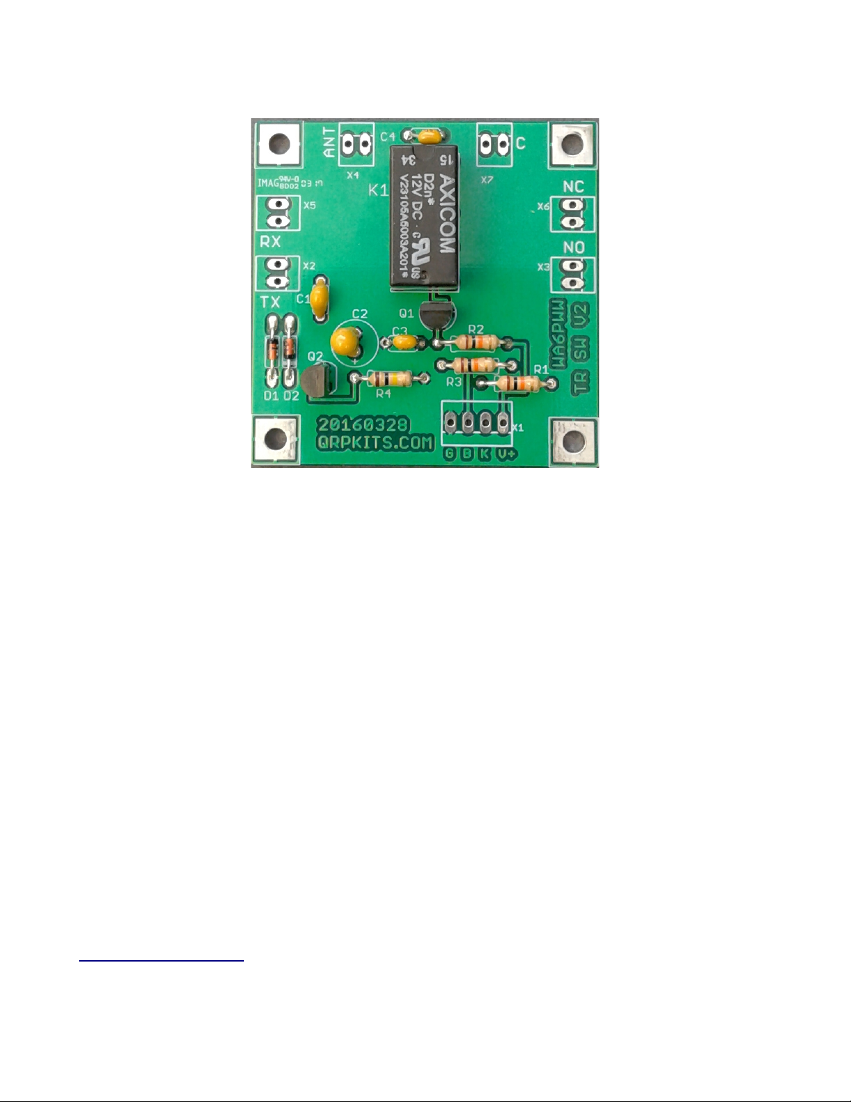
Board Layout
Note: Pin 1 of X1 is the pad closest to the X1 Label (on the right above) and is the connection point
for 12V power. The leftmost pin (4) is ground connection.
Install the following components on the PC board.
Resistors
R1 10K Ohm, 1/4W, Brown-Black-Orange-Gold
R2 10K Ohm, 1/4W, Brown-Black-Orange-Gold
R3 10K Ohm, 1/4W, Brown-Black-Orange-Gold
R4 100K Ohm, 1/4W, Brown-Black-Yellow-Gold
Capacitors
C1 22pF or 47pF or 100pF monolithic capacitor (use 47pf for most bands from 80-20M)
C2 4.7uf Tantalum Note: align + side lead with + pad on board outline
C3 0.1uF monolythic ceramic, marked 104
C4 0.1uF monolythic ceramic, marked 104
Easy TR Switch 20170209 4

Transistors and diodes
Q1 2N3906 (align flat to board outline with center pin away from flat)
Q2 BS170 (align flat to board outline with center pin away from flat)
D1 1N4148 (align band to board outline)
D2 1N4148 (align band to board outline)
Misc parts
K1 xicom V23105 Relay, (only fits one way due to pin configuration)
Features and Operation
The TR switch provides switching between two separate sets of contacts to two separate output/input
pairs.
It will sense RF input on the TX inputs and switch at about 100mW of RF and can be used over a
frequency range of 160-6M and up to 100 Watts of RF under matched conditions.
Manual switching can be enabled by grounding pin 3 (B) of the control inputs (X1) and then grounding
pin 2 (K) to switch the relay manually.
If automated switching is not reliable on certain frequencies, the value of C1 may need to be adjusted
up or down. In general, increase C1 for lower frequency operation and decrease it for high frequency
use.
The supplied 47pF capacitor should work over most bands from 80-20M. The kit also includes a 22pF
and 100pF for improved performance on bands outside this range.
Easy TR Switch 20170209 5

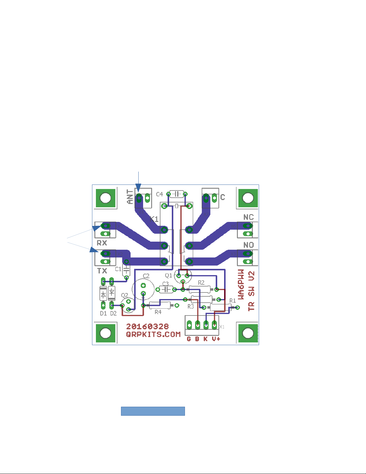
Board Connections
The ntenna, RX and TX as well as the second switched pair (C, NC and NO) are as shown above.
For the pads marked RX, TX, NC and NO, the connection is to the upper pad and the lower pads are
connected to ground on the board as shown above.
For antenna switching between a receiver and Transmitter, you will only need to use the NT, RX and
TX connections.
The uxiliary contact set can be utilized to mute audio of a receiver by switching its output to a
resistor during transmit instead of the speaker or headphones.
This would be accomplished by connecting the audio to the ux input and connecting a speaker to the
normally closed (NC) output and a 10 ohm or so resistor from the normally open output to ground.
Easy TR Switch 20170209 6
RX
GND
TX
GND
Normally Closed
GND
Normally Open
GND
Antenna Aux.
If the TR switch is embedded into another system, jumper wires can be used to the appropriate pads
for signals, power and control lines (if needed).
To connect ot BNC or other external RF type connectors, the center will go to the upper pads and the
shell or ground connection will go to the lower pads as shown below.
You can see the pads with traces and connected to ground by looking at the back of the board. s a
guide, the trace locations are shown in the drawing below.
The additional switched contacts (if used), are connected in the same manner .
X1: Control and Power input
Pin 1: V+; Pin next to X1 label on board, connects to 12 power supply.
Pin 2: K; External keying control line. Ground this pin to key the TR switch manually.
Pin 3: B: Bypass control line. Ground to disable automatic switching for manual keying.
Pin 4: Ground for power, control and key signals
Easy TR Switch 20170209
Connect
center of
BNC here
Connect
center of
BNC here
1234
V+
K
B
G
X1

Troubleshooting
The Easy TR switch is intended to be easy to assemble and should operate without any problems.
However, if it fails to operate, there are a few things to check:
Check the board for cold solder joints, these will appear rough rather than shiny. If in doubt, reheat
connections to ensure a good connection.
Check for any solder bridges or solder whiskers that may short between adjacent pads
Verify correct location and orientation of the diodes D1 and D2 as well as the transistors Q1 and Q2.
They should be oriented as shown on the PC board outlines.
Verify that power and ground are connected to Pads 1 and 4 of X1.
Test by connecting Pad 2 of X1 to ground with 12 power applied to Pin 1. You should be able to hear
the relay click. If not, recheck components and solder connections as indicated above.
When applying RF to the TX input, you should hear the relay click. If possible, test at 7-10Mhz first to
verify function and if not working at low or high frequencies, increase or decrease the value of C1 and
retest.
Capacitor C1 is part of the RF sensing circuit that controls the automatic TR switching.
The kit is supplied with a 47pF capacitor for C1 and for most HF applications, this will work well.
For very low frequency use, (~3MHZ or below), using the included 100pF or larger capacitor may
improve switching performance
For high frequencies (~ 25MHz or above) 22pF or even less will usually be sufficient.
Switching performance for power levels below 1 Watt may be improved by larger values of C1
Some experimentation may be required to find the optimal capacitance for your specific application.
If you still experience problems, or have any questions, please contact us at [email protected]
and we will be happy to assist you.
Easy TR Switch 20170209 8
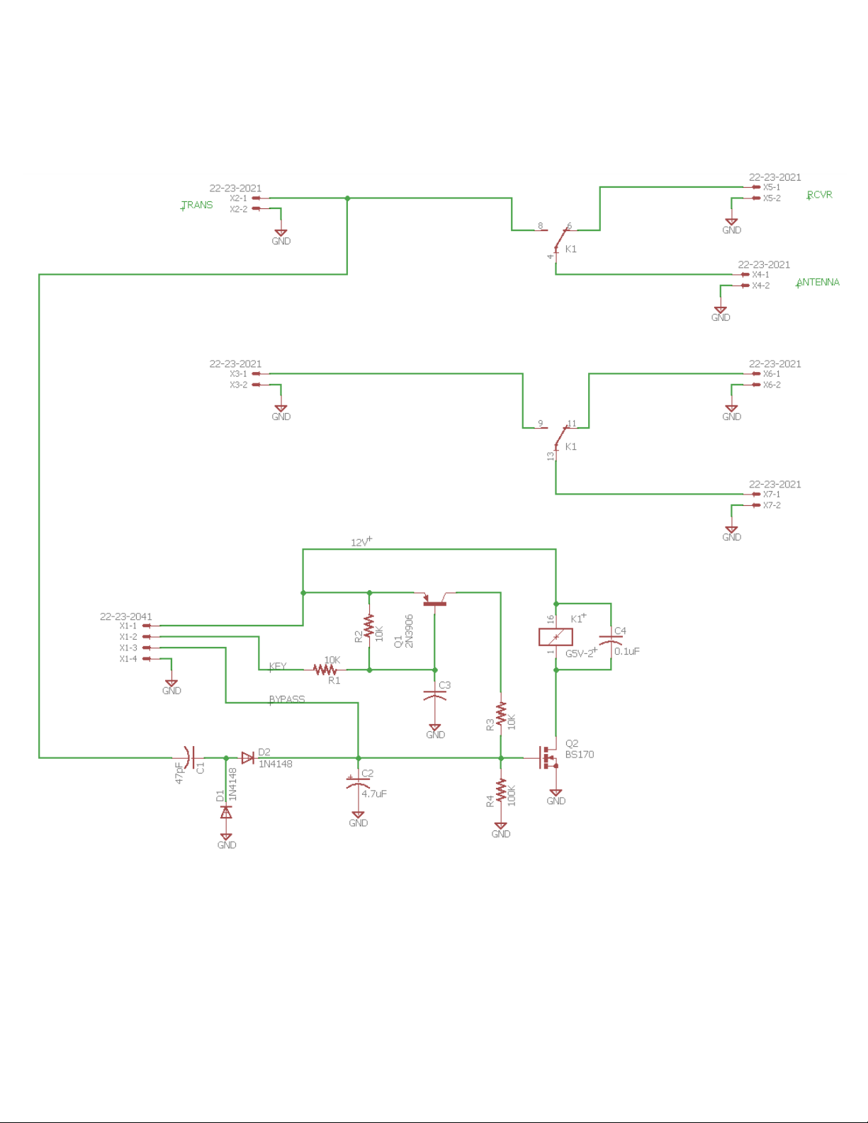
Schematic
Easy TR Switch 20170209 9
Other manuals for Easy TR Switch
1
Table of contents
Other Pacific Antenna Switch manuals


