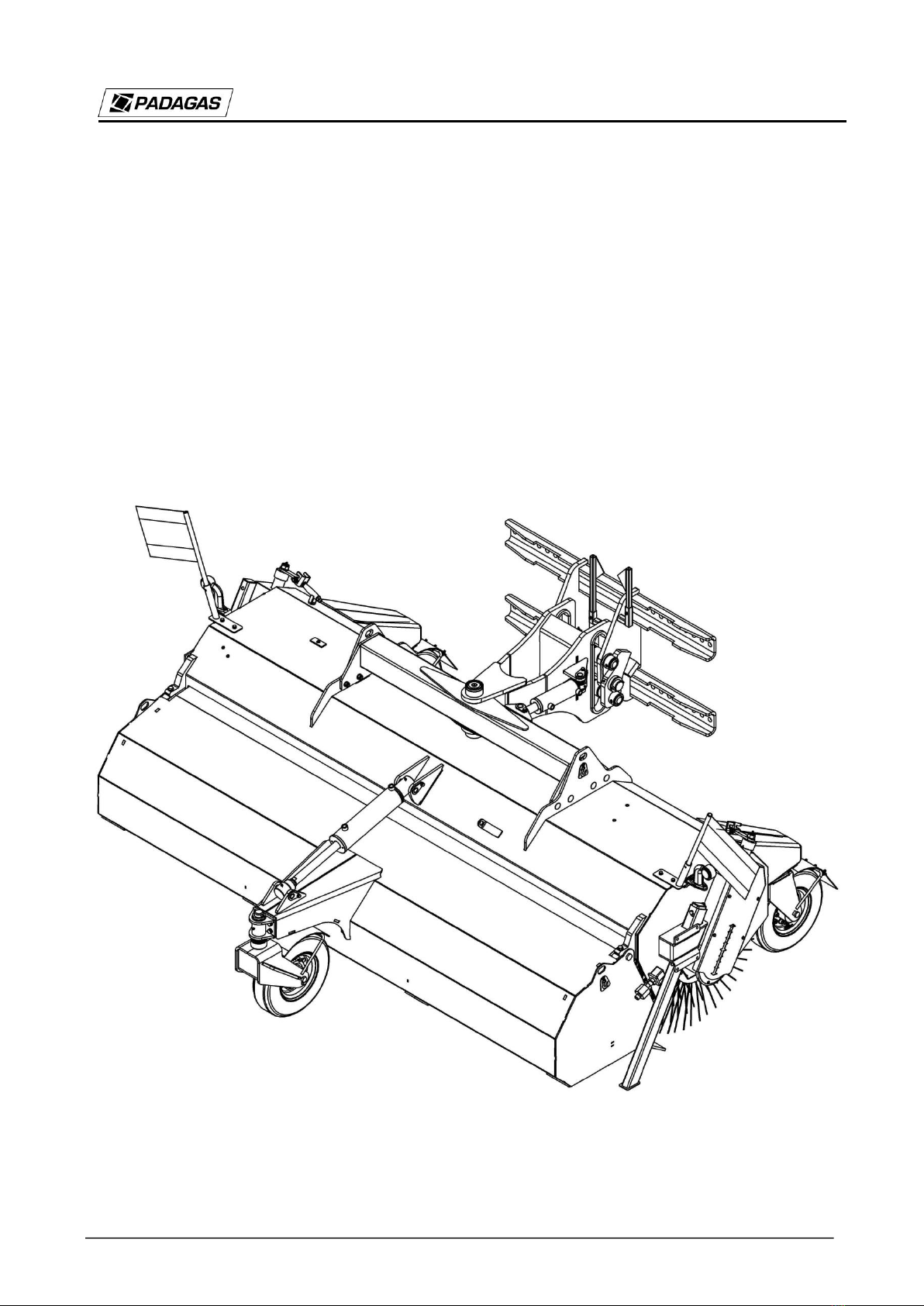
Padagas PROFI H-2101 User manual

PROFI H
©V. Padagas ir ko., UAB. All rights reserved.
User Manual
PROFI H –2101/2501/2801

PROFI H
©V. Padagas ir ko., UAB. All rights reserved.
CONTENTS
1. INTRODUCTION ................................................................................................................................................ 6
1.1 BASIC DATA................................................................................................................................................. 6
1.2 THE INTENDED USE.................................................................................................................................... 6
2. SAFE HANDLING INSTRUCTIONS....................................................................................................................... 7
2.1 GENERAL..................................................................................................................................................... 7
2.2 PERSONNEL QUALIFICATION AND TRAINING............................................................................................. 7
2.3 POTENTIAL HAZARDS IN CASE OF BREACH OF SAFETY INSTRUCTIONS ..................................................... 7
2.4 PRINCIPLES OF SAFE OPERATION .............................................................................................................. 8
2.5 SAFETY INFORMATION FOR THE OPERATOR / USER ................................................................................ 8
2.6 SAFETY INSTRUCTIONS FOR MAINTENANCE, INSPECTION AND MOUNTING ......................................... 10
2.7 RE-MOUNTING AND REPLACING PARTS INDEPENDENTLY...................................................................... 11
2.8 INSTRUCTION AND WARNING NOTES AND SYMBOLS ON THE SWEEPING MACHINE............................. 11
3. ADDITIONAL DATA.......................................................................................................................................... 13
3.1 DOCUMENTS PROVIDED WITH THE SWEEPING MACHINE ...................................................................... 13
3.2 WARRANTY CONDITIONS ......................................................................................................................... 13
3.3 DISPOSAL OF THE SWEEPING MACHINE AT COMPLETION OF THE OPERATION...................................... 13
4. DIRECTIONS FOR USE...................................................................................................................................... 14
4.1 TECHNICAL DATA...................................................................................................................................... 14
4.2 DESCRIPTION OF THE SWEEPING MACHINE............................................................................................ 14
4.3 LIGHTS....................................................................................................................................................... 15
5. SWEEPING MACHINE OPERATION.................................................................................................................. 15
5.1 CONNECTING THE SWEEPER TO THE TRACTOR ....................................................................................... 15
5.2 CONNECTION OF THE SWEEPING MACHINE TO THE HYDRAULIC SYSTEM .............................................. 16
5.3 TEST OPERATION ..................................................................................................................................... 16
5.4 OPERATING THE SWEEPING MACHINE..................................................................................................... 16
5.5 HYDRAULIC UNIT ...................................................................................................................................... 18
5.6 LUBRICATION SCHEME ............................................................................................................................. 19
6. SWEEPER EQUIPMENT.................................................................................................................................... 20
6.1 ADDITIONAL EQUIPMENT......................................................................................................................... 20
6.2 PAKABU RĖMAS........................................................................................................................................ 20
6.3 HIDRAULINIAI KOMPONENTAI IR PAPILDOMOS OPCIJOS........................................................................ 20
6.4 ELEKTRINIAI KOMPONENTAI .................................................................................................................... 21

PROFI H
©V. Padagas ir ko., UAB. All rights reserved.
1. INTRODUCTION
1.1 BASIC DATA
This user manual provides instructions for the use, safe operation and maintenance of the sweeping
machine.
If you do not understand the instructions provided herein, please contact the dealer or the
manufacturer directly.
Particularly important information and mandatory instructions are presented in bold with a note
CAUTION alongside.
Information on hazards and protective measures as well as work safety instructions bear the
following mark:
and are provided in the section "Safe Handling Instructions".
The clock symbol indicates the technical maintenance periods.
1.2 THE INTENDED USE
Sweeping machines are used to clean roads, squares, parking lots and other hard surfaces on streets
and pavements. The sweeping machine is supplied with plastic (polypropylene) sweeping segments
and supporting casters. The sweeping machine can be used with front loaders that have a coupling
with floating or non-floating hydraulic function. If the sweeping machine is used for other purposes,
the manufacturer does not assume any responsibility for the consequences of such use. In case of
misuse the warranty is deemed void.

PROFI H
©V. Padagas ir ko., UAB. All rights reserved.
2. SAFE HANDLING INSTRUCTIONS
2.1 GENERAL
The user manual includes important information which must be followed when mounting the device,
during its operation and maintenance. The staff are required to read these manual before mounting
the device or handing it over for operation. Instructions must be kept within the user's reach.
It is necessary to observe not only the general safety instructions provided in this section, but also all
other safety requirements.
In all cases, follow the safe work instructions and rules.
All work related to servicing and repairs must be carried out when the sweeping machine is not
moving. The tractor engine must be off and the ignition key removed.
All screws must be checked after the work is finished. Tighten them, if necessary.
Make sure other people are not present in the work area.
When sweeping, the supports of the machine must be raised to the upper position. Upon completion
of the work, lower the supports to avoid deformation of the brush.
Damaged hydraulic hoses must be replaced immediately.
If the machine is used on the open road, observe the road traffic regulations.
2.2 PERSONNEL QUALIFICATION AND TRAINING
PROFI H-type sweeping machine may be operated, handed over for use and repaired only by persons
who are able to do so and are fully aware of potential dangers. The responsible person is appointed
and the works are overseen by the operator. If the personnel are not aware of the essential rules of
use, they must be trained and instructed. The operator must verify if the personnel have fully
understood the content of the user manual.
Only authorised specialists are allowed to carry out repair works other than those described in this
manual.
2.3 POTENTIAL HAZARDS IN CASE OF BREACH OF SAFETY
INSTRUCTIONS
Non-compliance with safety instructions can cause injuries to people and damage the environment
and the machine. Failure to comply with safety instructions may result in forfeiture of the right to
claim damages.
In some cases, such non-compliance may lead to the following:
- Risk to persons working in unprotected areas
- Basic malfunction of the machine

PROFI H
©V. Padagas ir ko., UAB. All rights reserved.
- Inefficient commissioning or repair methods
- Injuries to persons due to mechanical and chemical effects
- Damage to the environment due to leakage of hydraulic oil
2.4 PRINCIPLES OF SAFE OPERATION
It is obligatory to follow the safety instructions described herein, the existing national / local
regulations to prevent accidents as well as any rules relating to the user's workplace, operation or
safety.
It is mandatory to observe safety rules and regulations to prevent accidents, as set out by responsible
professional associations.
Account must be taken of the manufacturer's safety precautions.
When working or driving on public roads, it is obligatory to follow the state regulations and road
traffic rules as well as the manufacturer's instructions.
2.5 SAFETY INFORMATION FOR THE OPERATOR / USER
- Before starting the work, get familiar with all instruments, connecting elements and their functions.
It is too late to do this when the operation has started.
- Users must wear tightly-fitting clothes. Avoid loose-fitting garment.
- Before the operation, check the stability and security of the chair in accordance with its mounting
method, also check whether it is not damaged. Furthermore, see if the hydraulic hoses are in the
correct position, as bent or pressed hoses may be damaged quickly.
- Before attaching or removing the hoses, check if mountings are put / set correctly.
- Observe the permitted axle loads, gross vehicle weight and size limits. Check and attach transport
equipment, i.e., lighting, warning devices and protective devices, if any.
- If the lights mounted on the truss structures are hidden/covered in the current position, additional
lamps must be attached.
- When the sweeping machine is connected to the tractor, it is necessary to adjust the suspension
according to the level indicators (Fig. 1).

PROFI H
©V. Padagas ir ko., UAB. All rights reserved.
Fig. 1. Level indicators
- Before moving and operating the machine it is necessary to inspect the immediate area (see if there
are no children). Be sure visibility is sufficient.
- It is prohibited to take on passengers while working or driving the machine
- Make sure the hydraulic system will not start and will not lower accidentally during travel.
- The driving (driver's) position may not be changed during travel.
- Avoid sharp bends in hilly areas and on slopes.
- Take into account the effects on movement, control and braking, which may be caused by the
running machine.
- The travel speed must be adapted to local road traffic rules. The machine may be put into operation
once the proper functioning of all the security measures and devices has been verified.
- Do not stop in the work area.
- The rotating device can be activated only if there are not any people present in the rotation area.
- Hydraulic parts of the machine include presses and shears.
- Before leaving the sweeping machine, it is necessary to lower the supports to the ground or to adjust
the supporting casters so that the brush is not deformed. Remove the ignition key, and check and
make sure that the machine will not start or run suddenly.
- After turning off, the machine still features some weakening inertia. At that time, do not approach
the machine. Wait until the machine is completely turned off.
- The pressure of the hydraulic unit must be nulled.
- Under high pressure, liquids (hydraulic oil) can penetrate the skin and cause severe tissue damage.
In case of injury seek medical attention immediately. The risk of contracting the infection!
- Hydraulic hoses must be mounted only at zero pressure of the hydraulic machine.

PROFI H
©V. Padagas ir ko., UAB. All rights reserved.
- Hydraulic hoses must be replaced no later than 6 years of the operation (including not more than 2-
year storage).
- Check the hydraulic hose lines regularly. Replace the damaged or worn-out lines. Hose lines, which
are used to replace the worn-out ones, must comply with the manufacturer's instructions.
- Leaked fluids are dangerous to the environment. They must be collected and removed immediately.
- When detecting the leakage or collecting liquids, the use of protective equipment is necessary to
prevent injury.
2.6 SAFETY INSTRUCTIONS FOR MAINTENANCE, INSPECTION AND
MOUNTING
The user must ensure that all maintenance, inspection and mounting works are carried out by
authorised specialists who are completely familiar with the user manual. Any works may be
performed only when the machine is turned off. It is mandatory to follow the machine turn-off
process described in the manual.
If the repair work is carried out on a raised device, it must be stabilised using appropriate supporting
elements.
When changing the brush segments, use proper tools and wear gloves.
Oils must be removed in accordance with regulations.
Upon completion of works, immediately re-attach and turn on all the safety and protective
equipment.
When the machine is being started up after repair, comply with provisions set out in the section on
the operation of the machine.
If the sweeping machine has not been used for more than 4 weeks, it should be
checked thoroughly before next operation.
Technical condition of the sweeping machine must be checked in the following cases:
Before starting the operation
At specified maintenance periods
After repair or a break in operation
The period of use of hydraulic hoses and tubes may not be longer than 6 years.
Regular check must include:
All screws, which must be tightened, if necessary
Tightness of the hydraulic unit
Proper fixation of all safety devices

PROFI H
©V. Padagas ir ko., UAB. All rights reserved.
Condition of sliding details and functioning of safety catches
Checking and cleaning the panels and lubrication points
Lubrication of the specified lubricating points.
The first time, check bolts and nuts after 5 hours of work. Then perform the check periodically (about
every 50 hours of work), and tighten them, if necessary.
A = thread size
Resistance class is indicated on the screw head.
A
3.6
5.6
6.8
8.8
10.9
12.9
M4
1
1.34
2.6
3.04
4.31
5.15
M5
1.96
2.65
5.1
6.03
8.48
10.2
M6
3.43
4.51
8.73
10.3
14.71
17.65
M7
5.59
7.45
14.22
17.16
24.52
28.44
M8
8.24
10.79
21.57
25.5
35.3
42.17
M10
16.67
21.57
42.17
50.01
70.61
85.32
M12
28.44
38.25
73.55
87.28
122.58
147.1
M14
45.11
60.8
116.7
135.27
194.17
235.36
M16
69.63
93.16
178.46
210.84
299.1
357.94
M18
95.13
127.4
245.17
289.3
411.88
490.34
M20
135.33
180.44
348.14
411.88
576.5
669.26
M22
126.4
245.17
470.72
558.98
784.45
941.44
M24
230.46
308.91
598.21
710.99
1000.28
1196.42
Torque for metric threads corresponds to DIN 13.
The friction value of 0.14 is specified for new bolts, which were not lubricated. The above are
reference values recommended by various manufacturers of screws. We do not accept responsibility
in cases these values are followed.
2.7 RE-MOUNTING AND REPLACING PARTS INDEPENDENTLY
Re-installation of the machine and replacement of parts is allowed only upon prior agreement and
consent of the manufacturer. Original spare parts and manufacturer's approved parts guarantee safety.
The use of other parts may forfeit the user's right to claim damages in the event of failure or accident.
2.8 INSTRUCTION AND WARNING NOTES AND SYMBOLS ON THE
SWEEPING MACHINE
The description and meaning of the instruction and warning notes and symbols indicated on the
sweeping machine are provided in Table No. 1.
Table No. 1. Instruction and warning notes and symbols on the sweeper

PROFI H
©V. Padagas ir ko., UAB. All rights reserved.
No.
The symbol (sign) or contents
of the note
Meaning of the symbol (sign)
1
PROFI H
Sweeping machine type.
2
CAUTION! Before starting the operation, adjustment or
maintenance works, the user must read the user manual.
3
CAUTION! When the tractor engine is running, keep at a
safe distance from the sweeper. The risk of leg or foot injury!
4
WARNING: BEWARE OF PRESSING!
When the sweeper is operating, unauthorised persons must
not be present in areas marked with this sign. If any work has
to be done in these areas, ensure a stable position of the
sweeper and disconnect it from the power source.
5
CAUTION! Keep your hand away from the area with potent
risk of pressing. If the structural components of the sweeper
move, your hands or fingers might be pressed.
6
CAUTION! Before touching parts of the machine, wait until
it stops working completely. After turning the engine off,
sweeping segments keep rotating for some time and may
cause injury.

PROFI H
©V. Padagas ir ko., UAB. All rights reserved.
3. ADDITIONAL DATA
3.1 DOCUMENTS PROVIDED WITH THE SWEEPING MACHINE
The following documents are supplied together with the sweeping machine:
User manual
Warranty card
3.2 WARRANTY CONDITIONS
V.Padagas ir Ko, UAB provides warranty against manufacturing defects, excluding parts that are
produced by other companies, for the period of 12 months from the date of loading or 6 months from
the date of delivery of the sweeping machine to the consumer.
This warranty does not cover defects that are caused by unreasonable use of the sweeping machine
by the consumer, including incorrect assembly, improper maintenance and operation, or accidents
due to operations at a higher speed or load than specified in the manual, improper lubrication or
inappropriate storage.
CAUTION
The purchaser of the device must require the vendor to properly prepare warranty and
damage claim documents. If the date of purchase is not specified in the documents or
the seal of the maintenance company is missing, the manufacturer may refuse to accept
the claims from the owner of the device.
3.3 DISPOSAL OF THE SWEEPING MACHINE AT COMPLETION OF THE
OPERATION
If the user has decided to terminate the operation of the device, it must be disposed of by handing
over to the recycling company specified by state institutions. Parts remaining after repair should also
be handed over to the recycling company.

PROFI H
©V. Padagas ir ko., UAB. All rights reserved.
4. DIRECTIONS FOR USE
4.1 TECHNICAL DATA
Sweeping machine PROFI H
2101
2501
2801
Working width (m)
2.08
2.48
3.05
Sweeping segment diameter (mm)
800
800
800
Hydraulic angling (o)
-
±20
±20
Weight (kg)
884
941
980
Drive
Hydraulic
motor
Hydraulic
motor
Hydraulic
motor
Max flow rate (l/min at max 200
bar)
808080
Water pump (V)
12
12
12
Water tank (l)
150/300
150/300
150/300
Dimensions and weight are indicative and may vary. The manufacturer reserves the right to modify
the product design and construction without separate notice.
The attachable sweeping machine is designed for:
Tractors
Front loaders.
4.2 DESCRIPTION OF THE SWEEPING MACHINE
The main components of the sweeping machine are: the frame, the shaft, suspension, supporting
casters and garbage collection bins.
The shaft is rotated by the hydraulic actuator. The torque for the shaft is produced by the hydraulic
motor, which is rotated by connecting the hoses to the tractor's hydraulic system.
The sweeping machine has three cleaning positions, i.e., straight, turned to the right and turned to the
left (Fig. 2). Cleaning positions are set mechanically by turning the rod or hydraulically with the use
of hydraulic cylinder.
In PROFI H model the garbage bin is used for the collection of garbage and other bulk material from
the surface being cleaned.

PROFI H
©V. Padagas ir ko., UAB. All rights reserved.
Fig. 2. Sweeping machine positions
4.3 LIGHTS
Pay attention to other road users. Attached units must be equipped with lights as required by specific
conditions or when visibility of the tractor is obscured by equipment.
5. SWEEPING MACHINE OPERATION
Before using the sweeping machine, the operator must read the user manual. Regulations of
directives on proper operation must be observed.
5.1 CONNECTING THE SWEEPER TO THE TRACTOR
The device is mounted on the front or rear suspension of the machine. Hydraulic hoses are connected
to the hydraulic system.
The sweeping machine is connected to the tractor, which is intended for that purpose, without any
problems. The connection does not require additional tools. Check if all coupling elements are in
order.
When connecting the hydraulic hoses to the tractor, ensure that they are not twisted, without loops
and protected from damage.
In order to ensure optimum operation of the sweeping machine:
The device requires a hydraulic circuit with reverse flow and a quick-connect coupling;
Check if the rotating parts (hydraulic motor, brush shaft) are mounted appropriately (at least
once in 8 working hours)

PROFI H
©V. Padagas ir ko., UAB. All rights reserved.
CAUTION!
Regulations of directives on mounting points are mandatory
5.2 CONNECTION OF THE SWEEPING MACHINE TO THE HYDRAULIC
SYSTEM
Remove the quick-connected plugs from protective holders (or remove the fixing elements) and
connect them to the external links of the tractor's hydraulic system. When connecting the hydraulic
hoses, make sure the hoses are not bent and are protected from damage.
Each time the hydraulic system of the sweeping machine is connected, it is necessary to raise the
machine to an 800-mm height and test the hydraulic functions. It is necessary to fully understand the
sweeping machine functions and only then operate the device.
CAUTION!
DO NOT open the container of the sweeping machine without raising it from
the ground.
5.3 TEST OPERATION
The sweeping machine must be tested:
Before starting the operation
Periodically (at least once a month)
After repair works
The operator must ensure that the hydraulic hoses are replaced after a certain period of time, even if
there are no visible defects. Hydraulic hoses should not be used for longer than 6 years. The date of
manufacture and the permissible dynamic pressure are specified on the hose.
5.4 OPERATING THE SWEEPING MACHINE
After checking all the safety equipment and hydraulic connections, you may start using the sweeping
machine.
The working speed of the sweeping machine depends on the type of surface being cleaned and the
amount of rubbish (but must not exceed 10 km/h).
When operating the sweeping machine:
If there are three supporting casters, it is necessary to monitor that the sweeping machine is
running on the casters during operation.

PROFI H
©V. Padagas ir ko., UAB. All rights reserved.
It is necessary to observe that the weight of the loader does not press the sweeping
machine.
Connect the hydraulic hoses so that the shaft rotates in the right direction.
Make sure the casters and the garbage bin do not interfere with the shaft.
The turned position of the sweeping machine may be selected only when working without the
garbage bin.
Before sweeping, check if the garbage bin is mounted properly and the shaft is pressed to the
base. Pressing the shaft is carried out by raising or lowering the shaft. When the rings are
worn out, the shaft must be lowered so that the sweeping segments would touch the surface
being cleaned.
If the lower rubber of the bin is worn out, the bin must be tipped to press the rubber to the
ground. Bin tipping is adjusted by shortening the tipping rod of the hydraulic cylinder (Fig.
4).
Note: When assembling a new shaft, make sure the axle is not bent. Repair of the hydraulic system
may be carried out only in an authorised workshop. The safe condition of the sweeping machine must
be monitored during its daily operation.
Fig. 3. Bin regulation scheme.
Fig. 4. Bristle pressure adjustment

PROFI H
©V. Padagas ir ko., UAB. All rights reserved.
Fig. 5. Bristle pressure adjustment recommendations
5.5 HYDRAULIC UNIT
Each time the unit is disconnected from the tractor's hydraulic system, it is necessary to reduce the
partial pressure of the hydraulic unit.
Before starting the operation, always check the oil level in the hydraulic system of
the tractor.
If the device has not been used for more than 4 weeks, it should be checked
thoroughly before next operation.
The period of use of hydraulic hoses may not be longer than 6 years.
When the quick-connect couplings are detached from the tractor, a suitable hydraulic stopper must be
put on the hydraulic plug, and the hydraulic hoses must be hung in the place provided to protect them
from contamination and mechanical damage.
CAUTION!
Maximum instantaneous pressure within the hydraulic system is 200 bar.
Maximum instantaneous flow rate within the hydraulic system is 85 l/min.

PROFI H
©V. Padagas ir ko., UAB. All rights reserved.
5.6 LUBRICATION SCHEME
Fig. 6. Lubrication scheme
The sweeper must be lubricated at least every 16 hours.
Recommended lubrication oil: LT-42 or LT-43.

PROFI H
©V. Padagas ir ko., UAB. All rights reserved.
6. SWEEPER EQUIPMENT
6.1 ADDITIONAL EQUIPMENT
Single tank watering system.
Volume of the single tank watering system –150 l.
Double tank watering system.
Volume of the double tank watering system –300 l.
6.2 HITCH FRAME
Floating hitch frame.
The floating hitch frame is used only on in the front of the tractor.
The floating hitch frame has a universal suspension mount
(Multibracket).
6.3 HYDRAULIC COMPONENTS AND ADDITIONAL OPTIONS
Hydraulic motor.
The oil pressure and flow of the tractor should be adjusted only to half
of maximum parameters of the hydraulic motor.
The shaft rotation speed should be approximately 80-120 rpm.
Flow controller.
If the oil flow rate of the tractor is above 80 l/min, it is recommended
to install a flow control valve in the hydraulic system to avoid
overloading the hydraulic system of the sweeper. The oil flow controls
the rotation speed of the shaft. The shaft rotation speed should be
approximately 80-120 rpm.

PROFI H
©V. Padagas ir ko., UAB. All rights reserved.
Hydraulic unit.
A hydraulic control unit is installed to control the hydraulic functions of
the sweeper. The main valves required for operation of the sweeper are
installed in this control unit.
Hydraulic valve.
The valve is required to operate the raised box.
6/2 solenoid valve
A double action control circuit for two hydraulic functions can be used
using the 6/2 solenoid valve.
Electrical control is required to operate the valve
Draining (Pos. 1).
The drain hose is connected when the pressure in the return hose can
exceed the allowable limit.
The drain hose must be connected to allow the oil to flow freely into the
tank of the tractor
6.4 ELECTRICAL COMPONENTS
The water pump of the watering system must be connected via a switch,
using a 10 A fuse in line.
The connector must be installed on the positive (red) current wire.
The water pump of the watering system.
The water pump is used to ensure a steady flow of water over any
operating range.
The pump voltage is 12 V or 24 V.
Marker light.
The marker lamp clearly defines the width of the vehicle.
This manual suits for next models
2
Table of contents
Other Padagas Blower manuals