Padagas FKM-GKM 130 User manual

FKM-GKM
©UAB V. Padagas ir ko. All right reserved.
User manual
FKM-GKM
130/150/180/230

FKM-GKM
©UAB V. Padagas ir ko. All right reserved.
CONTENT
1. INTRODUCTION............................................................................................................................... 5
1.1 GENERAL INFORMATION......................................................................................................... 5
1.2 INTENDED USE.......................................................................................................................... 5
2. WORK SAFETY.................................................................................................................................. 6
2.1 GENERAL ....................................................................................................................................6
2.2 EMPLOYEES’ QUALIFICATION AND TRAINING ...................................................................6
2.3 POSSIBLE DANGER IN CASE OF FAILURE TO COMPLY WITH THE SAFETY
PRECAUTIONS.................................................................................................................................. 6
2.4 PRINCIPLES OF SAFE OPERATION........................................................................................ 7
2.5 SAFETY INSTRUCTIONS FOR THE USER / OPERATOR ....................................................... 7
2.6 SAFETY INSTRUCTIONS RELATED TO REPAIR, CONTROL AND INSTALLATION WORKS
............................................................................................................................................................ 9
2.7 MODIFICATIONS AND REPLACEMENT OF PARTS............................................................ 10
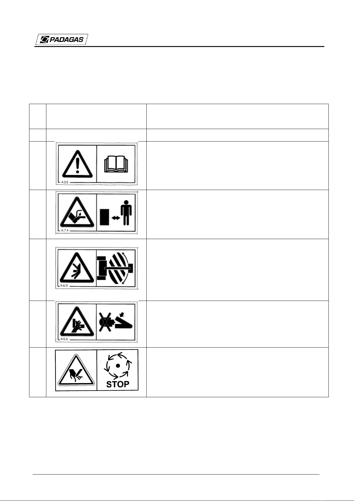
2.8 GUIDELINE AND WARNING NOTES AND SYMBOLS ON THE SWEEPER......................... 11
3. ADDITIONAL DATA ....................................................................................................................... 12
3.1 DOCUMENTS PROVIDED WITH THE SWEEPING MACHINE ............................................ 12
3.2 WARRANTY CONDITIONS.......................................................................................................12
3.3 DISPOSAL UPON TERMINATION OF USE............................................................................12
4. INSTRUCTIONS ON THE USE....................................................................................................... 13
4.1 TECHNICAL CHARACTERISTICS...........................................................................................13
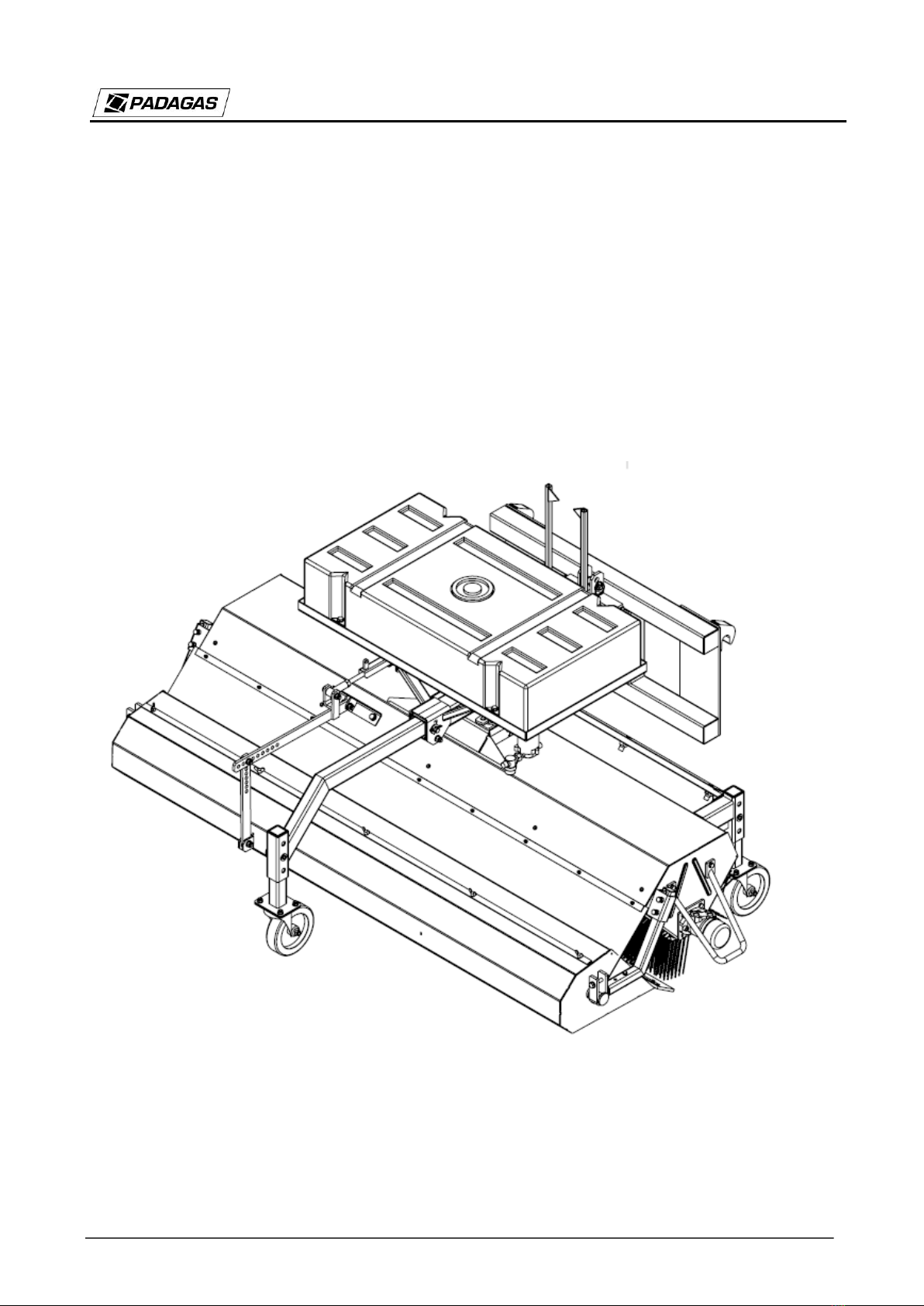
4.2 SWEEPER DESCRIPTION........................................................................................................ 14
4.3 LIGHTS ......................................................................................................................................14
5. USING THE SWEEPING MACHINE.............................................................................................. 14
5.1 PRECONDITIONS FOR THE SWEEPER’S ATTACHMENT TO THE TRACTOR .................. 15
5.2 CONNECTION OF THE SWEEPING MACHINE TO THE HYDRAULIC SYSTEM................ 15
5.3 TEST OPERATION .................................................................................................................... 15
5.4 OPERATING THE SWEEPING MACHINE .............................................................................. 16
5.5 HYDRAULIC UNIT.................................................................................................................... 17
6. SWEEPER EQUIPMENT ................................................................................................................ 18
6.1 ADDITIONAL EQUIPMENT..................................................................................................... 18
6.2 HYDRAULIC COMPONENTS AND ADDITIONAL OPTIONS................................................ 18
6.3 ELECTRICAL COMPONENTS.................................................................................................. 19

FKM-GKM
©UAB V. Padagas ir ko. All right reserved. 5
1. INTRODUCTION
1.1 GENERAL INFORMATION
This user manual provides the rules for the use, safe operation and maintenance of the
sweeping machine.
If you do not understand the information in the manual, contact the company selling the
sweeping machine or directly to the manufacturer.
Particularly important information and instructions are presented in bold and with the signal
word "ATTENTION".
Information and instructions for hazards, safety measures and work safety are labelled herein as
follows:
and are described in the section “Work Safety".
The clock symbol indicates periodic maintenance.
1.2 INTENDED USE
Sweeping machines FKM-GKM are used for cleaning and sweeping of roads, squares, car
parks and other hard surfaces of streets and pavements. The sweeping machines are supplied with
plastic (polypropylene) sweeping segments, and supporting wheels. The sweeping machines can be
used with front loaders equipped with a floating or non-floating hydraulic coupling. If the sweeping
machines are used for other purposes, the manufacturer assumes no responsibility for the
consequences of such use. In case of use of the sweeping machine for non-intended purposes, the
warranty is deemed null and void.

FKM-GKM
©UAB V. Padagas ir ko. All right reserved. 6
2. WORK SAFETY
2.1 GENERAL
This user manual includes important indications that must be observed when mounting the
equipment, during its operation and maintenance. Therefore the staff must read this manual before
coupling the equipment and putting it into service. Keep instructions in an accessible place.
It is necessary to take into account not only the general safety guidelines described in the
section "Work Safety", but also the following specific safety instructions.
The safety instructions and rules are to be observed in all cases.
All servicing and repair works must be carried out when the sweeper is in stationary position.
Turn off the tractor engine and remove the ignition key.
Check the fixing of all screws after finishing the works. Tighten them up, if necessary.
Make sure there no people are in the work area.
When sweeping, the supports must be lifted to the top position. After finishing the works, lower
the supports to avoid the brush deformation.
Damaged hydraulic hoses must be replaced immediately.
When using the sweeper on public roads, follow the road traffic rules.
2.2 EMPLOYEES’ QUALIFICATION AND TRAINING
The FKM-GKM sweeper may be used, put to service and repaired only by persons who are
well-equipped and well informed about potential hazards. A person responsible is assigned by the
operator who also monitors the workflow. If employees are unaware of essential rules of use, they
must be trained and instructed. The operator must check if the staff have fully understood the
instructions.
Repair works not described herein may only be performed by an authorized personnel.
2.3 POSSIBLE DANGER IN CASE OF FAILURE TO COMPLY WITH THE
SAFETY PRECAUTIONS
Failure to observe the safety instructions can cause damage to persons, the environment and the
machine. Non-compliance with safety guidelines may waive the right to claim damages.
In separate cases, non-compliance can lead to the following consequences:
- Danger to persons working in unprotected workplaces
- Malfunctioning of the equipment
- Inefficiency of the described methods of putting into service and repair works
- Damage to persons due to mechanical and chemical effects

FKM-GKM
©UAB V. Padagas ir ko. All right reserved. 7
- Damage to the environment due to hydraulic oil leakage
2.4 PRINCIPLES OF SAFE OPERATION
It is mandatory to observe the safety guidelines described herein, the applicable national / local
regulations on preventing accidents, as well as the rules relating to the workplace, operation and
safety.
It is mandatory to observe occupational safety rules and regulations on preventing accidents,
which are determined by responsible professional associations.
The manufacturer's safety instructions must be taken into account.
When working and moving on public roads, follow the applicable regulations and road traffic
rules as well as the manufacturer's instructions.
2.5 SAFETY INSTRUCTIONS FOR THE USER / OPERATOR
- Before starting the work, go through all the devices, connectors and their functions. It is too
late to do that after the sweeper operation has been started.
- Users’ clothing should be tight-fitting. Avoid loose clothing.
- Before operation, check the stability and safety of the seat with regard to the method of
fitting, and whether it is not damaged. Also, check if the hydraulic hoses are in place, as the damage
may occur if bent or under load.
- Before mounting or removing the hoses, place the fasteners in their correct position.
- Adhere to the permissible axle loads, overall weight and transport dimensions. Check and
attach the transport equipment –lights, warning devices and protective devices, if any.
- If in any position the light fitted to the trusses is tucked away / hidden, additional lamps must
be fitted.
- When connecting the sweeper to the tractor, the suspension must be adjusted according to the
level indicators (Fig. 1).

FKM-GKM
©UAB V. Padagas ir ko. All right reserved. 8
Fig. 1. Level indicators
- Before you start driving and operating the equipment, inspect the nearest area (if there are no
children). Make sure you have enough visibility.
- While working or driving the machine, it is forbidden to take passengers.
- Ensure that the sweeper hydraulic system does not accidentally start up or go down during
driving.
- Driving (driver’s) position cannot be changed while driving.
- Avoid sudden turns when driving in hilly terrain.
- Take into account the effects of movement, control and braking caused by the activated
sweeper.
- Choose your driving speed according to the street and local road traffic regulations. - Operate
the sweeper only after making sure that all safety measures and devices are functioning.
- It is prohibited to make a stop in the work area.
- The turning device can only be actuated if there are no people in the turning area.
- The hydraulic parts of the machine contain presses and scissors.
-Before leaving the sweeping machine, lower the supports to the ground, or adjust the
supporting wheels to avoid the brush deformation. Remove the ignition key, check and make sure
that the machine will not start suddenly or start rolling.
- When the machine is switched off, a dangerous weakening inertia occurs. At that time, do not
get near the machine. Wait until the machine is completely off.
- Hydraulic unit pressure must be null.

FKM-GKM
©UAB V. Padagas ir ko. All right reserved. 9
- High-pressure liquids (hydraulic oil) can penetrate the skin and severely damage the tissues.
In case of injury, seek medical advice immediately. Danger of infection!
- Install the hydraulic hoses only under zero hydraulic pressure.
- The hydraulic hoses must be changed not later than after 6 years of operation (including up to
2 years of storage).
- Regularly check hydraulic hoses, replace them if they are damaged or obsolete. The hose used
for replacement must meet manufacturer's requirements.
- Leaked liquids are hazardous to the environment. They must be collected and removed
immediately.
- When looking for or collecting leaks, protective measures must be used to avoid injury.
2.6 SAFETY INSTRUCTIONS RELATED TO REPAIR, CONTROL AND
INSTALLATION WORKS
The user must ensure that all repair, inspection and installation works are carried out by
authorized specialists who are familiar with the machine's operating instructions. All work can only
be performed when the machine is switched off. Follow the procedure for switching off the machine
described in the instructions.
If repair works are carried out on the lifted device, it must be stably supported by suitable
supporting elements.
When replacing the brush segments, use appropriate tools and wear gloves.
Remove lubricants in accordance with applicable provisions.
After completing the work, immediately install and activate all safety and protective
equipment.
When putting into service after repairs, the guidelines specified in the operating instructions
must be followed.
If the sweeper was not used for more than 4 weeks, it must be checked carefully
before operation.
Check the sweeper's technical condition in the following cases:
Before starting the sweeper operation;
At a specified frequency of inspection;
After repair or a break in operation.
The life of the hydraulic hoses and tubes must not exceed 6 years.
During the inspection, check the following:

FKM-GKM
©UAB V. Padagas ir ko. All right reserved. 10
Fixing of all screws; tighten them up, if necessary;
Tightness of the hydraulic unit;
Appropriate fitting of all protective devices;
The condition of sliding parts and the functioning of safety locks;
Check and clean the sweeper shellboards and lubrication points;
Lubricate the specified lubrication points.
For the first time, check the tightness of screws and nuts after 5 working hours, then check
them periodically (approximately every 50 hours); tighten if necessary.
A = thread size
The resistance class is indicated on the screw head.
A
3.6
5.6
6.8
8.8
10.9
12.9
M4
1
1,34
2,6
3,04
4,31
5,15
M5
1,96
2,65
5,1
6,03
8,48
10,2
M6
3,43
4,51
8,73
10,3
14,71
17,65
M7
5,59
7,45
14,22
17,16
24,52
28,44
M8
8,24
10,79
21,57
25,5
35,3
42,17
M10
16,67
21,57
42,17
50,01
70,61
85,32
M12
28,44
38,25
73,55
87,28
122,58
147,1
M14
45,11
60,8
116,7
135,27
194,17
235,36
M16
69,63
93,16
178,46
210,84
299,1
357,94
M18
95,13
127,4
245,17
289,3
411,88
490,34
M20
135,33
180,44
348,14
411,88
576,5
669,26
M22
126,4
245,17
470,72
558,98
784,45
941,44
M24
230,46
308,91
598,21
710,99
1000,28
1196,42
All tightening torques refer to metric threads according to DIN 13.
Friction number 0.14 refers to new screws with no lubrication applied. The above are indicative
values recommended by the various screw manufacturers. We take no responsibility for the use of
those values.
2.7 MODIFICATIONS AND REPLACEMENT OF PARTS
Sweeper modification and replacement of any parts is allowed only with prior agreement of the
manufacturer and its consent. Original spare parts and parts approved by the manufacturer guarantee
safety. Use of other parts may invalidate the consumer's right to claim damages in the event of a
malfunction or an accident.

FKM-GKM
©UAB V. Padagas ir ko. All right reserved. 11
2.8 GUIDELINE AND WARNING NOTES AND SYMBOLS ON THE SWEEPER
Description and meaning of the guideline and warning notes and symbols provided on the
sweeper are presented in Table No. 1.
Table No. 1. Guideline and warning notes and symbols on the sweeper
No.
Symbol (mark) or the contents
of the note
Meaning
1
FKM-GKM 130/150/180/230
Sweeping machine type.
2
WARNING! The user must read the user manual before
starting the sweeper operation, adjustment or maintenance
works.
3
WARNING! When the tractor engine is running, stand at a
safe distance from the sweeper. A risk of injury to the leg or
feet!
4
CAUTION: CRUSH HAZARD
Unauthorized persons are not allowed to stand in areas
marked with this sign during the sweeper operation. If any
works must be performed in these areas, ensure a stable
sweeper position and disconnection from the power source.
5
WARNING! Keep hands away from the crush hazard area –
if the sweeper's structural components move, there is a risk
of crushing your hands or fingers.
6
WARNING! Before touching the parts of the machine, wait
until they stop completely. When the engine is switched off,
the sweeping segments will rotate for a while and may cause
injury.

FKM-GKM
©UAB V. Padagas ir ko. All right reserved. 12
3. ADDITIONAL DATA
3.1 DOCUMENTS PROVIDED WITH THE SWEEPING MACHINE
The documents provided with the sweeper are as follows:
User manual
Warranty certificate
3.2 WARRANTY CONDITIONS
V.Padagas ir Ko, UAB guarantees that the sweeping machine will be free from manufacturing
defects, except for parts produced by other companies, for a period of 12 months from the date of
loading or 6 months from the date of delivery to the consumer.
This warranty does not apply to defects which occurred due to irrational use of the sweeper,
including improper assembly, improper maintenance, improper handling and accidents, operation at
higher speed or load than stated in the instructions, improper lubrication or improper storage.
NOTE
The buyer must request the seller to properly prepare the warranty and complaint
documents. If the documents do not contain the date of purchase of the sweeper or the seal
of the maintenance company, the manufacturer may refuse to accept the claims from the
sweeper owner.
3.3 DISPOSAL UPON TERMINATION OF USE
If the user decides to terminate the sweeper operation, the machine must be handed over to the
waste recycling company designated by authorities. The replacement parts remaining after repair
must also be transferred to the recycling company.

FKM-GKM
©UAB V. Padagas ir ko. All right reserved. 13
4. INSTRUCTIONS ON THE USE
4.1 TECHNICAL CHARACTERISTICS
Sweeping machine FKM-GKM
130
150
180
230
Working width (m)
1,25
1,44
1,75
2,25
Sweeping segment diameter
(mm)
520
520
520
520
Sweeping machine turning
angle (°)
25
25
25
25
Weight
249
264
283
316
Drive
Hidrovariklis
Hidrovariklis
Hidrovariklis
Hidrovariklis
Flow rate (l/min at max 175bar.
pressure)
25
25
25
25
Water pump (V)
12
12
12
12
Water capacity (l)
146
146
146
146
Dimensions and weight are preliminary and are subject to change. The manufacturer reserves
the right to change the product design and construction without a separate notice.
The sweeping machine may be attached to:
Tractors
Front loaders
The sweeper’s nameplate is located on the right side of the sweeper frame (Fig. 2).
Fig. 2. Location of the nameplate.

FKM-GKM
©UAB V. Padagas ir ko. All right reserved. 14
4.2 SWEEPER DESCRIPTION
The sweeper consists of the following main parts: frame, shaft, suspension, supporting wheels
and garbage collection box.
The sweeping machine shaft is a rotated by a hydraulic drive. The torque for the shaft is
provided by the hydraulic motor, which is rotated by connecting the hoses to the tractor's hydraulic
system.
The sweeping machine has three cleaning positions (Fig. 3): straight, turned right, and turned
left. The cleaning positions are set mechanically –rotated with a rod or hydraulically - rotated by a
hydraulic cylinder.
In the FKM-GKM model, the garbage collection box is designed to collect garbage and other
bulk materials from the cleaning surface.
Fig. 3. Positions of the sweeping machine
4.3 LIGHTS
Pay attention to other road users. Attached working units must be equipped with lights as
appropriate in specific conditions and in case if the equipment obscures the tractor lights.
5. USING THE SWEEPING MACHINE
Before starting the sweeper operation, the user must read the user manual. Directives for proper
operation must be followed.

FKM-GKM
©UAB V. Padagas ir ko. All right reserved. 15
5.1 PRECONDITIONS FOR THE SWEEPER’S ATTACHMENT TO THE
TRACTOR
The device is suspended on the front or rear of the tractor. The hydraulic hoses are connected to
the tractor’s hydraulic system.
The sweeper may be attached to the tractor if it does not cause problems and does not require
additional tools. Check the proper connection of all elements.
When connecting the hydraulic hoses to the tractor, ensure that they are not twisted, without
loops and protected from damage.
To ensure the optimal operation of the sweeping machine:
The sweeper requires a hydraulic circuit with backflow and a quick connect coupler.
Checking the turning parts (hydraulic motor, cleaning brush shaft) regularly (at least
every 8 working hours).
WARNING!
Strictly follow the guidelines on fixing points
5.2 CONNECTION OF THE SWEEPING MACHINE TO THE HYDRAULIC
SYSTEM
Remove the quick-connected plugs from protective holders (or remove the fixing elements) and
connect them to the external links of the tractor's hydraulic system. When connecting the hydraulic
hoses, make sure the hoses are not bent and are protected from damage.
Each time the hydraulic system of the sweeping machine is connected, it is necessary to raise
the machine to an 800-mm height and test the hydraulic functions. It is necessary to fully understand
the sweeping machine functions and only then operate the device.
CAUTION!
DO NOT open the container of the sweeping machine without raising it from
the ground.
5.3 TEST OPERATION
The sweeping machine must be tested:
Before starting the operation

FKM-GKM
©UAB V. Padagas ir ko. All right reserved. 16
Periodically (at least once a month)
After repair works.
The operator must ensure that the hydraulic hoses are replaced after a certain period of time,
even if there are no visible defects. Hydraulic hoses should not be used for longer than 6 years. The
date of manufacture and the permissible dynamic pressure are specified on the hose.
5.4 OPERATING THE SWEEPING MACHINE
After checking all the safety equipment and hydraulic connections, you may start using the
sweeping machine.
The working speed of the sweeping machine depends on the type of surface being cleaned and
the amount of rubbish (but must not exceed 10 km/h).
When operating the sweeping machine:
If there are three supporting casters, it is necessary to monitor that the sweeping machine
is running on the casters during operation.
It is necessary to observe that the weight of the loader does not press the sweeping
machine.
Connect the hydraulic hoses so that the shaft rotates in the right direction.
Make sure the casters and the garbage bin do not interfere with the shaft.
The turned position of the sweeping machine may be selected only when working without
the garbage bin.
Before sweeping, check if the garbage bin is mounted properly and the shaft is pressed to
the base. Pressing the shaft is carried out by raising or lowering support wheels. When the
rings are worn out, the support wheel must be lowered so that the sweeping segments
would touch the surface being cleaned.
If the lower rubber of the bin is worn out, the bin must be tipped to press the rubber to the
ground. Bin tipping is adjusted by shortening the tipping rod of the hydraulic cylinder
(Fig. 4).
Note: When assembling a new shaft, make sure the axle is not bent. Repair of the hydraulic
system may be carried out only in an authorised workshop. The safe condition of the sweeping
machine must be monitored during its daily operation.
Note: If sweeper with the box and side brush is monted in the tractors end, the sweeper
can not be torned to the sides.

FKM-GKM
©UAB V. Padagas ir ko. All right reserved. 17
Fig. 3. Wheel adjustment. Fig. 4. Box adjustment
Fig. 5. Pressing of the sweeping segments to the ground recommendations
5.5 HYDRAULIC UNIT
Before each sweeper disconnection from the tractor's hydraulic system, reduce the partial
pressure of the hydraulic unit.
Always check the oil level in the tractor's hydraulic system before starting working
with the sweeper.
If the machine has not been used for more than 4 weeks, it must be checked
carefully before operation.
The life of the hydraulic hoses must not exceed 6 years.
After disconnecting the hydraulic quick connect couplers from the tractor, the hydraulic
coupler plug must be covered with a special hydraulic stopper, and the hydraulic hoses must be hang
in a designated area to prevent the hoses from being contaminated or damaged.

FKM-GKM
©UAB V. Padagas ir ko. All right reserved. 18
6. SWEEPER EQUIPMENT
6.1 ADDITIONAL EQUIPMENT
Single tank watering system.
Volume of the single tank watering system –150 l.
Side broom.
During operation, the lower part of the sweeping bristle should be in
contact with the ground at 1/3 of the circle.
The force of contact with the ground is adjusted with the screw at the
flexible part
Side broom with hydraulic lift.
Side broom is lifted by a hydraulic cylinder.
During operation, the lower part of the sweeping bristle should be in
contact with the ground at 1/3 of the circle.
The force of contact with the ground is adjusted with the screw at the
flexible part
6.2 HYDRAULIC COMPONENTS AND ADDITIONAL OPTIONS
Hydraulic motor.
The oil pressure and flow of the tractor should be adjusted only to half
of maximum parameters of the hydraulic motor.
The shaft rotation speed should be approximately 80-120 rpm.
Non-return valve.
To prevent the sweeper shaft from being blocked abruptly after
changing the direction of the oil, it is possible to install an additional
non-return valve which allows the shaft to rotate in free running mode
without tearing.
Hydraulic lock.
Using when sweeping machine with hydraulic tipping.
Prevents the sweepr collector from opening.

FKM-GKM
©UAB V. Padagas ir ko. All right reserved. 19
6.3 ELECTRICAL COMPONENTS
The water pump of the watering system must be connected via a switch,
using a 10 A fuse in line.
The connector must be installed on the positive (red) current wire.
The water pump of the watering system.
The water pump is used to ensure a steady flow of water over any
operating range.
The pump voltage is 12 V or 24 V.
Marker light.
The marker lamp clearly defines the width of the vehicle.
This manual suits for next models
3
Table of contents
Other Padagas Blower manuals