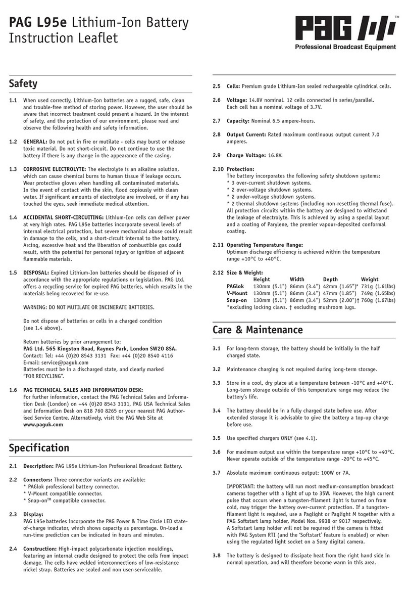
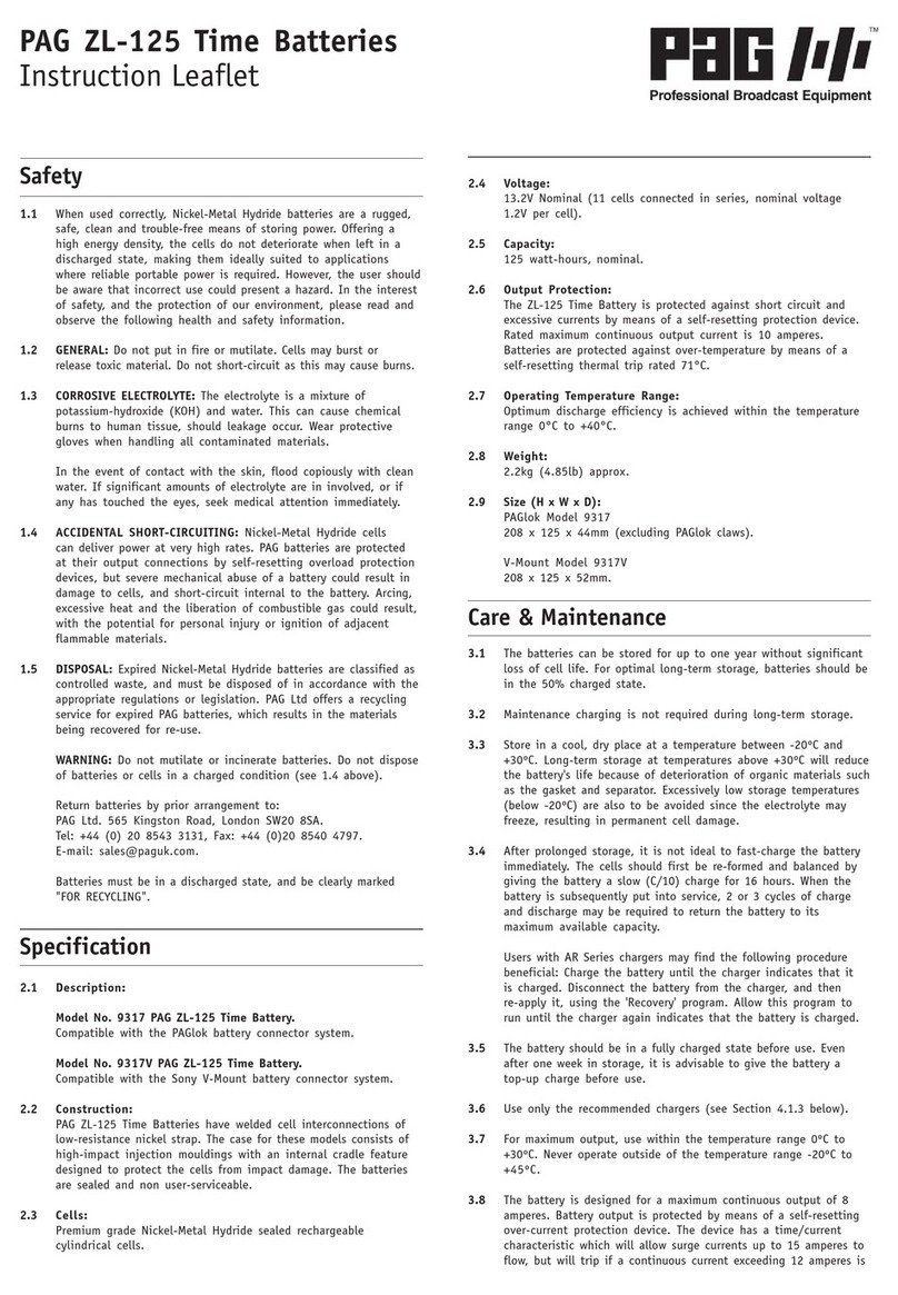
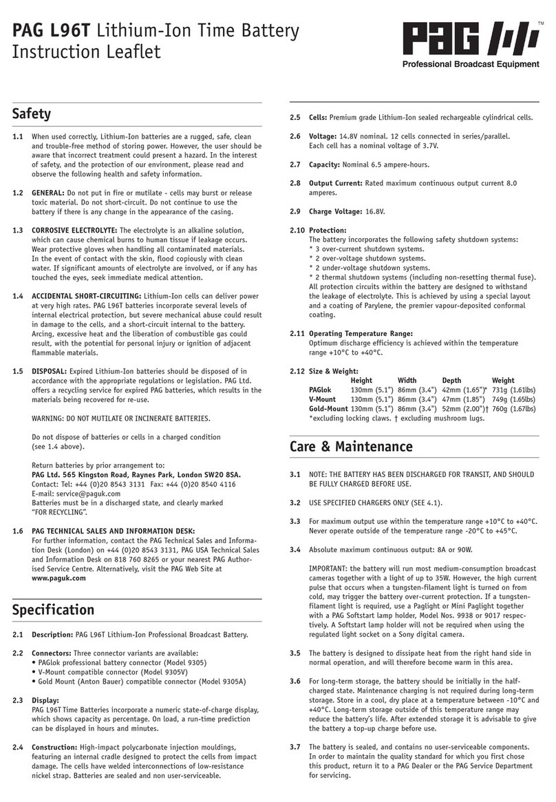
PAG PAGlink PL150 Series User manual

U5130 / AUG 2016
INTELLIGENT LINKING BATTERIES
PL150 Series
V-Mount & Gold Mount Models
Instruction Booklet

2
PAGlink V-Mount PL150 Battery
Main Battery Contacts
PAGlink
Latching
Mechanism
PAGlink
Contact
Block
Display
Button
PAGlink
Contact
Shield
PAGlink
Release
Button
Battery
Contacts
Display
Button
PAGlink Contacts
Battery Lock &
Release Button
PAGlink Gold Mount PL150 Battery

Thank you for choosing the PAGlink
PL150 Intelligent Linking Battery.
Please read the important safety information
and instructions before using the battery.
Keep the booklet for future reference and to
take with you when you travel by air with
your PAGlink batteries.
3
Contents
Section Page
1 Features 4
2 Specification 6
3 Charging 9
4 Discharging 10
5 Storage 11
6 Run-Time & Capacity Display 12
7 Battery Protection Features 16
8 PAGlink Features 17
9 Safety & Disposal 23
10 Guarantee 25
11 CE Compliance 26
12 UN Testing 27
13 Air Transportation 28

1. Features
• The PAGlink PL150 Series comprises batteries that are
compatible with the PAGlink V-Mount and PAGlink
Gold Mount systems.
• PL150 Series batteries have a capacity of 150Wh,
50% more than the PL96/94 models, and yet they
are the same size.
• The 150Wh models can be linked with the lower
capacity models for charge or discharge.
• The unique PAGlink system allows up to 8 batteries,
in any state of charge, to be linked for charge or
discharge.
• When linked, PAGlink batteries form a network that
allows them to communicate with each other and to
report to the camera as one large battery.
• The PAGlink system will automatically select the most
suitable batteries for discharge, according to their
charge status. Batteries do not discharge into one
another. The system ensures that the maximum linked
output is kept to a safe level.
• PAGlink batteries can deliver a current of up to 12A
when linked.
• The PAGlink connector system uses superior high-
current pin contacts.
• PAGlink batteries feature a built-in Run-Time &
Capacity Display. The V-Mount batteries offer a
4

choice between a numeric display or a 5-light
indicator. Under load, the remaining run-time can be
displayed for the total of all linked batteries. Capacity
is shown for each individual battery as a percentage.
• The display maintains accuracy by tracking performance,
and adjusting calibration values to compensate for the
ageing of the cells.
• PAGlink batteries will automatically detect and adapt
to a multitude of camera data systems: SMB (Sony), I2C
(IDX), reversed SMB (RED) and analogue 0V to 5V
(Anton Bauer) are supported.
• Batteries in any state of charge can be linked for
charging, in multiples of 8 or less. During charging,
the least-charged batteries are given priority.
The charge status for each battery is shown on its
own display.
• Power from the battery linking contacts can be
accessed using the PAGlink PowerHub, an accessory
power plate which provides four D-Tap ouputs
(interchangeable with Hirose and 2.1mm ) and a USB
output.
• PAGlink battery and charger firmware can be updated
easily by the customer, via external contacts, using an
update tool provided by PAG.
• The PAGlink latching mechanisms are external to the
battery and can be replaced, if damaged, without
opening the sealed case.
INTERNATIONAL PATENTS APPLY
5

2.1 Models covered by these instructions:
Model 9308 PAGlink V-Mount PL150e Battery.
Model 9309 PAGlink V-Mount PL150T Battery.
Model 9313 PAGlink Gold Mount PL150T Battery.
2.2 Camera Connection:
V-Mount: Models 9308 & 9309.
Gold Mount: Model 9313.
2.3 Run-Time & Capacity Display:
Models 9309 and 9313 feature a numeric display
which shows a run-time prediction on-load, expressed
in hours and minutes, and capacity as a percentage.
Model 9308 features a 5-light indicator which shows
a run-time prediction on-load, indicated by a
combination of lights, and capacity as a percentage
(each light represents 20%).
2.4 Construction: High-impact polycarbonate injection
mouldings designed to protect the cells from impact
damage. The battery case is sealed.
2.5 Replaceable Parts: The following assemblies can be
replaced in the event of damage, without opening
the sealed battery case:
PAGlink V-Mount rear latching mechanism.
PAGlink Gold Mount front contact assembly.
PAGlink Gold Mount rear battery lock assembly.
2.6 Cell Technology: Premium grade, Lithium-Ion sealed
rechargeable cylindrical cells.
6
2. Specification

2.7 Voltage: 14.8V nominal. 12 cells connected in
series/parallel. Each cell has a nominal voltage of
3.7V.
2.8 Capacity:
Nominal 10 Ampere-hours (150 Watt hours).
2.9 Output Current: The rated maximum continuous
output current for two or more linked batteries is
12 Amperes (8 Amperes for individual V-Mount
models and 10A for the Gold Mount model).
2.10 Charge Voltage: 16.8V.
2.11 Charge Times: Times given are for fully-discharged
PL150 batteries, using a PAGlink PL16 charger.
After 3 hours 1 battery will be charged to 95%.
2.12 Protection:
The battery incorporates the following safety shut-
down systems:
3 over-current shutdown systems.
2 over-voltage shutdown systems.
2 under-voltage shutdown systems.
3 thermal shutdown systems, including non-
resetting thermal fuse.
7
1 battery 3 hrs 45 mins
2 batteries 4 hrs 30 mins
4 batteries 9 hrs
6 batteries 13 hrs
8 batteries 18 hrs
16 batteries 36 hrs

8
The protection circuit within the battery is
conformally coated to resist electrolyte, and
designed to ensure operation of the safety systems
in the event of damage to the battery.
2.13 Firmware Updates: Battery firmware can be updated
easily by the user in the field, via the battery
contacts. Updates enable you to take advantage of
the technological advances that PAG introduces to
accommodate developments in camera technology.
An update tool can be provided by PAG.
2.14 Temperature Range:
Charging:
0°C to +45°C Optimum +10 to +40°C
+32°F to +113°F Optimum +50°F to +104°F
Discharging:
-20°C to +50°C Optimum +10°C to +40°C
-4°F to +122°F Optimum +50°F to +104°F
Storage:
-10°C to +40°C Optimum 0°C to +20°C
+14°F to +104°F Optimum +32°F to +68°F
2.15 Dimensions (H x W x D):
V-Mount Models:
133mm (5.2") x 84mm (3.3") x 50mm (1.9")
Gold Mount Model:
129mm (5”) x 87mm (3.42”) x 58mm (2.25”)
2.16 Weight (All Models):
770g (1.7lbs) approx.

9
3.1 IMPORTANT: READ THE CHARGER HANDBOOK BEFORE
ATTEMPTING TO CHARGE THE BATTERY.
3.2 The following PAGlink chargers will charge PAGlink
batteries, individually or linked, regardless of their
capacity or state of charge:
V-Mount Chargers:
9707 PAGlink PL16 Charger 8 per channel
9711 PAGlink PL16+ Charger 8 per channel
9708 PAGlink Cube Charger 4 per channel
9710 PAGlink Micro Charger 8 per channel
Gold Mount Chargers:
9707A PAGlink PL16 Charger 8 per channel
9711A PAGlink PL16+ Charger 8 per channel
Anton Bauer Li-Ion chargers are also suitable.
Four or more linked batteries can be charged on
each position, depending on the charger model and
firmware version.
PAG Pulsar and Quasar Gold Mount chargers are not
suitable for charging PAGlink Gold Mount batteries.
The following chargers will charge PAGlink PL150
batteries individually or linked (batteries must be
within 40% state-of-charge of each other to be
charged fully):
V-Mount:
9702V PAG Cube Charger 4 per channel
9702VR PAG RMC4X Charger 8 per channel
3. Charging

10
Constant-voltage V-Mount Li-Ion chargers of other
reputable manufacturers are also suitable.
3.3 PAGlink batteries display their individual status,
during charging, on their built-in display. When
using PL16 chargers, the characters of the PL150T
numeric display can be inverted, for legibility, with
a single button press. The display reverts automati-
cally after removal from the charger.
3.4 The batteries incorporate a precision temperature
sensor which will inhibit charging if their tempera-
ture is below 0°C. See Section 2 Specification for
the charging temperature range of PAGlink PL150
batteries.
4.1 The batteries incorporate a precision fixed end-of-
discharge cutoff set to 12.5V, as measured by the
battery. This cutoff will only operate if the battery
capacity is less than 5%, eliminating unwanted
battery operation due to high current and low
battery temperature.
4.2 The maximum continuous discharge current for a
single V-Mount PL150 battery is 8A (90W approx.),
and for a single Gold Mount battery it is 10A (120W
to 150W approx.). The batteries incorporate an
accurate precision current limit, and consumption
above this, for more than 5 seconds, will trigger the
over-current protection, turning the battery output
off.
4. Discharging

11
4.3 If the battery is discharged at too high a rate, even
momentarily, the protection circuit may be triggered,
disconnecting the battery output.
4.4 If the battery has been shut down by its protection
circuit it can be recovered by simply removing it
from the load and pressing the display button,
provided the battery still retains some charge.
NOTE: The battery features a computer reset
function. In exceptional circumstances a compu-
ter reset may be required. This is achieved by
holding the display button in for 20 seconds.
4.5 Where total continuous consumption is above 8A,
(or 10A for Gold Mount models) two or more PAGlink
batteries should be linked. This will increase the
maximum continuous discharge current to 12A.
4.6 The battery may be discharged within the tempera-
ture range -20°C to +50°C, but for optimum
performance, +10°C to +40°C is recommended.
The operating time will be shorter in conditions of
low temperature, and discharging will be electroni-
cally inhibited if the battery temperature is below
-20°C. When the battery has been discharged at a
high rate it will become warm, and it is advisable to
let it cool before charging it.
5.1 PAGlink batteries can be left stacked on a charger
until required; the charger will keep them topped-up
ready for use, with no detrimental effects.
5.2 For long-term storage, batteries should be initially
5. Storage

in a half-charged state, and unlinked. Storing
batteries linked accelerates the rate at which they
self-discharge.
5.3 Maintenance charging is not required during long
term storage.
5.4 Store in a cool, dry place at a temperature between
0°C and +20°C. Long-term storage outside of this
temperature range may reduce the battery’s life.
5.5 The battery should be in a fully-charged state before
use. After extended storage it is advisable to give
the battery a top-up charge before use.
6.1 The Numeric Display (Models 9309 & 9313):
The battery is able to display a numeric run-time
prediction against load, and charge status as a
percentage.
(1) When connected to a camera that is turned on,
two presses of the battery’s display button will show
a predicted run-time against the given load, expressed
in hours and minutes. When batteries are linked the
run-time displayed relates to the total for the
connected batteries. The battery requires a minimum
of 5 seconds before it is able to give an accurate run-
time prediction.
12
12
6. Run-Time & Capacity Display

13
(2) A single button press of the display, whether the
battery is off or on-load, shows a percentage figure
of available capacity. When batteries are linked this
figure still relates to the battery’s individual capacity.
(3) When battery capacity drops below 5% the
display will indicate that the battery should be
charged by pointing to the empty battery symbol.
(4) When the battery is fully charged the display will
indicate 100%.
6.2 The 5-Light Display (Model 9308):
The battery is able to indicate a run-time prediction,
against load, and charge status as a percentage.
(5) When connected to a camera that is turned on,
two presses of the battery’s display button activates
the time display. The ‘HRS’ LED will flash twice.
(6) The number of hours will then be indicated by
the number of lit segments: each light = 1 hour.
4
3
56

14
78
9
(7) The ‘MINS’ light will then flash twice.
(8) The number of minutes will be indicated by the
number of lit segments: each light = 10 mins. When
batteries are linked the run-time displayed relates
to the total for the connected batteries.
(9) A single button-press, whether the battery is on
or off-load, displays charge status in terms of
percentage. When batteries are linked this figure still
relates to the battery’s individual capacity. The LEDs
light clockwise, starting from the top right:
5 Lights = 80 - 100% remaining
4 Lights = 60 - 79% remaining
3 Lights = 40 - 59% remaining
2 Lights = 20 - 39% remaining
1 Light = 10 - 19% remaining
1 Light flashing = 0 - 10% remaining
6.3 In-Viewfinder Battery Status
Battery status can be shown as a percentage of
available capacity in the viewfinder/LCD of cameras
designed to accept this data. Different data standards
are used by camera and battery manufacturers.

15
PAGlink V-Mount batteries automatically adjust the
data output standard to support the following: SMB
(Sony), I2C (IDX) and analogue 0V to 5V (Anton
Bauer).
PAGlink Gold Mount batteries are compatible with
the camera data system that allows both PAGlink and
Anton Bauer batteries to display their capacity in the
viewfinder/LCD.
When the batteries are linked, the data displayed in
the viewfinder/LCD is for the combined capacity
available.
RED Cameras
PAGlink batteries can be programmed easily by the
user to provide capacity data in the viewfinder of
RED cameras. Press the display button twice, and hold
down on the second press until ‘RED’ appears (on the
numeric display) or until the top 2 segments are lit
(5-Light indicator). This indicates that the battery is
now compatible with the RED data protocol (reversed
SMB). When the battery is connected to a camera
with a different data protocol it will automatically
adjust to communicate with that system. To return to
RED compatibility repeat the two-button-press process.
6.4 PAGlink Battery Reader
A PAGlink Battery Reader is available that will
display data stored in the battery’s microprocessor.
It provides usage and performance information that
is beneficial for managing a large battery inventory.
Slide the Reader over the battery contacts and the
following information can be revealed via the Reader’s
buttons: state of charge as a percentage; available
capacity in Ah; cell temperature in degrees celsius;

16
number of charge/discharge cycles; voltage; full
capacity in Ah; date of manufacture and firmware
version.
7.1 Over-charge Protection
Charging will be inhibited if the battery voltage
exceeds a pre-set level.
7.2 Over-discharge Protection
When the battery voltage reaches 12.5V, discharging
is inhibited.
7.3 Over-current Protection
If a single battery is subjected to a current greater
than 8A (for the V-Mount Model) or 10A (for the Gold
Mount model) but less than 15A, the output will be
turned off after 5 seconds. If the current is greater
than 15A, the output will be turned off immediately.
In either case, the battery display will be inoperative
and there will be no voltage available at the
terminals. The battery can be reset by removing it
from the load and pressing the display button.
7.4 Thermal Protection
Software protection inhibits charging if the battery
temperature is below 0°C. Return the battery to the
charger when the battery temperature rises above 0°C.
Software protection inhibits discharging if the battery
temperature falls to -20°C, or if it rises to +70°C.
The output can be restored when the battery
temperature becomes within the specified range
by pressing the display button.
7. Battery Protection Features

17
A thermal fuse is incorporated within the battery
construction as a ‘backstop’ protection device, and
this cannot be reset. In the unlikely event of this
fuse operating, please contact PAG or your dealer.
7.5 Construction
Cells are housed in high-impact, polycarbonate
injection mouldings designed to protect the cells
from impact damage. Circuits are coated with
Parylene, the premier vacuum-deposited conformal
coating, making them resistant to electrolyte.
Internal wiring is rated for high current and high
temperature, and is double-insulated for added
safety and protection.
8.1 PAGlink V-Mount System:
8. PAGlink Features
Align the V-Mount connectors and push the battery
down until you hear a click (the lock is then engaged).

18
To release the battery, hold down the release button
(1) and slide the battery up (2).
PAGlink V-Mount Terminals:
Front Terminals

19
Base Terminals
Rear Terminals

Align the gold studs of one battery with the claws
on the front of another. Slide the battery across
until you hear a click and the white locking
indicator is visible on the battery release button.
20
To release the battery, hold down the release button
and slide the battery to the left.
PRESS TO
RELEASE
8.2 PAGlink Gold Mount System:
UNLOCKED
LOCKED
This manual suits for next models
6
Table of contents
Other PAG Camera Accessories manuals