PairGain FRE-860 Instructions for use

PG-FLEX
TECHNICAL PRACTICE
FRE-865
PG-Flex
FRE-865
MADE IN USA
PairGain
TELEPHONE COMPANY PROPERTY
FRE-860
PG-Flex
FRE-860
MADE IN USA
PairGain
TELEPHONE COMPANY PROPERTY
FRE-867
PG-Flex
FRE-867
MADE IN USA
PairGain
TELEPHONE COMPANY PROPERTY
FRE-868
PG-Flex
FRE-868
MADE IN USA
PairGain
TELEPHONE COMPANY PROPERTY
Remote Terminal Enclosures
Model List No. Part No. CLEI Code
FRE-860 1150-2360-01 VAMRMS0A
1A 150-2360-11 VAMRRS0A
FRE-865 1150-2365-01 VAMRNS0A
1A 150-2365-11 VAMRVS0A
1B 150-2365-12 VAMRNS0A
FRE-867 1150-2367-01 VAMRP40A
1A 150-2367-11 VAMRU40A
1B 150-2367-12 VAMRP40A
FRE-868 1150-2368-01 VAMRT40A
2150-2368-02 VAMRTS0A
3150-2368-03 VAMRS40A
4150-2368-04 VAMRSS0A
™363-860-100-02§¨
Section 363-860-100-02

363-860-100-02, Revision 02
ii March 28, 2000 FRE-860, FRE-865, FRE-867, and FRE-868
Revision History of This Practice
©Copyright 2000 PairGain Technologies, Inc.
PairGain®and PG-Plus®are registered trademarks, and The Power Behind DSL Access™, and the PairGain logo design are
trademarks of PairGain Technologies, Inc. No right, license, or interest to such trademarks is granted hereunder, and you agree
that you shall assert no such right, license, or interest with respect to such trademarks. All other product names mentioned in this
document are used for identification purposes only and may be trademarks or registered trademarks of their respective companies.
Information contained in this document is company private to PairGain Technologies,Inc., and shall not be modified, used, copied,
reproduced or disclosed in whole or in part without the written consent of PairGain.
Information furnished by PairGain Technologies is believed to be accurate and reliable. However, no responsibility is assumed by
PairGain Technologies for its use, nor for any infringement of patents or other rights of third parties which may result from its use.
No license is granted by implication or otherwise under any patent or patent rights of PairGain Technologies. PairGain
Technologies reserves the right to change specifications at any time without notice.
Revision Release Date Revisions Made
01 October 27, 1999 Initial Release
02 March 28, 2000 Added List 1B to the FRE-865 and FRE-867 models.

363-860-100-02, Revision 02 Using This Technical Practice
FRE-860, FRE-865, FRE-867, and FRE-868 March 28, 2000 iii
USING THIS TECHNICAL PRACTICE
Three types of messages, identified by icons, appear in the text.
INSPECTING YOUR SHIPMENT
Upon receipt of the equipment:
•Unpack each container and visually inspect the contents for signs of damage. If the equipment has been
damaged in transit, immediately report the extent of damage to the transportation company and to PairGain.
Order replacement equipment, if necessary.
•Check the packing list to ensure complete and accurate shipment of each listed item. If the shipment is short
or irregular, contact PairGain as described in the “Limited Warranty” on page 13. If you must store the
equipment for a prolonged period, store the equipment in its original container.
Notes indicate information about special circumstances.
Cautions indicate the possibility of equipment damage or the possibility of personal injury.
Electrostatic Discharge (ESD) susceptibility symbols indicate that a device or assembly is
susceptible to damage from electrostatic discharge.

Table of Contents 363-860-100-02, Revision 02
iv March 28, 2000 FRE-860, FRE-865, FRE-867, and FRE-868
TABLE OF CONTENTS
Overview ____________________________________________________________________________ 1
Installation and Turn-up _______________________________________________________________ 4
Required Tools and Test Equipment................................................................................................. 4
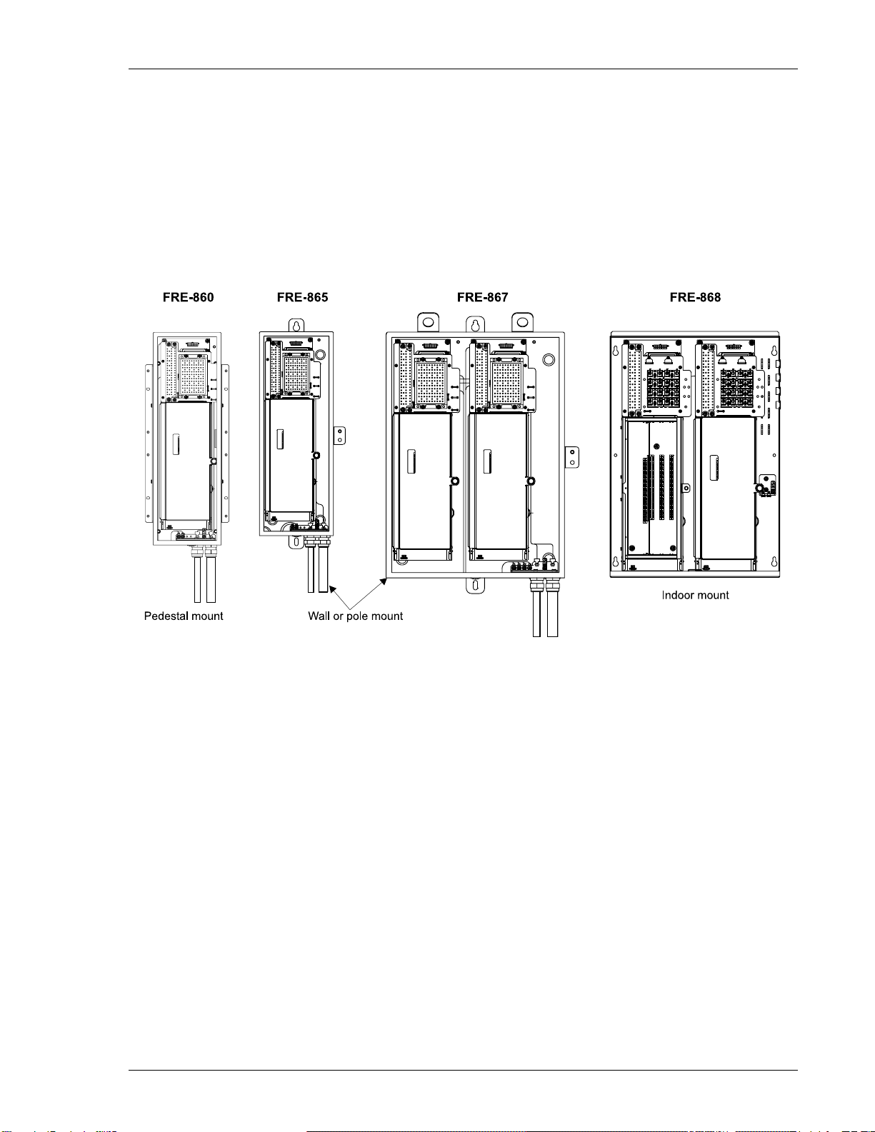
Installing the FRE-860 RT Enclosure ............................................................................................... 5
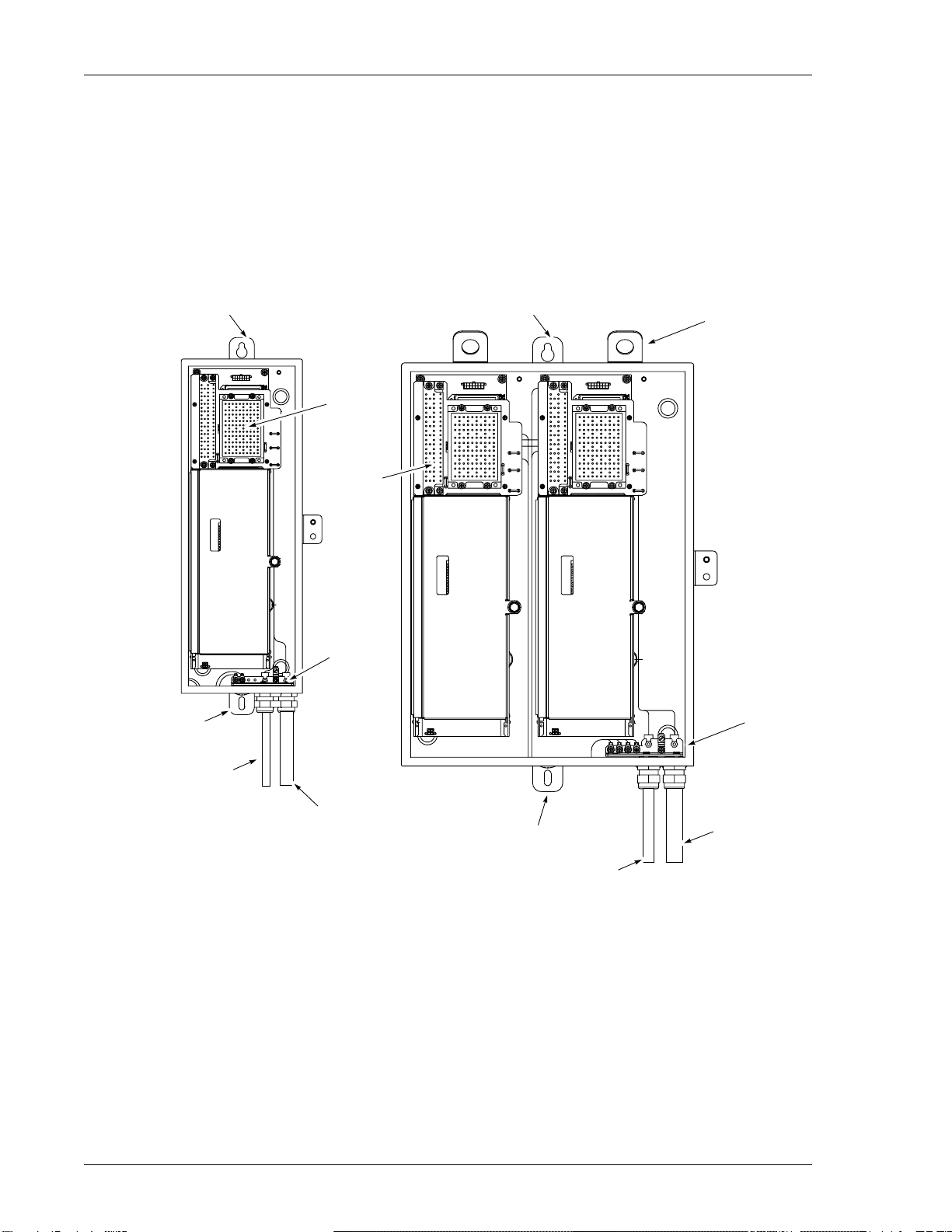
Installing the FRE-865 and FRE-867 RT Enclosures ....................................................................... 6
Installing the FRE-868 RT Enclosure ............................................................................................... 8
Chassis Ground Wiring ................................................................................................................... 10
Cabling Verification........................................................................................................................ 11
Turn-Up and Testing ....................................................................................................................... 11
Close the Housing............................................................................................................................ 11
Troubleshooting _____________________________________________________________________ 11
Abbreviations _______________________________________________________________________ 12
Product Support _____________________________________________________________________ 13
Technical Support............................................................................................................................ 13
World Wide Web............................................................................................................................. 13
Limited Warranty ............................................................................................................................ 13
Returns............................................................................................................................................. 14
FCC Compliance............................................................................................................................. 15
Modifications................................................................................................................................... 15

363-860-100-02, Revision 02 Overview
FRE-860, FRE-865, FRE-867, and FRE-868 March 28, 2000 1
OVERVIEW
The PairGain®PG-Flex®FRE-860, FRE-865, FRE-867, and FRE-868 Remote Terminal (RT) Enclosures
(see Figure 1) conveniently mount RT line units (LU) and channel units (CU). The RT Enclosures provide
termination points for subscriber circuits, HDSL, auxiliary power, and metallic bypass pairs.
The units described by this document get power from the HDSL lines connected to the COT Shelf. For each
doubler installed between the COT Shelf and RT Enclosure, two additional power pairs are required from the COT
Shelf to the RT Enclosure.
Figure 1. Internal Views of the Enclosure

Overview 363-860-100-02, Revision 02
2 March 28, 2000 FRE-860, FRE-865, FRE-867, and FRE-868
Table 1. FRE-860, 865, 867, and FRE-868 Features
RT Enclosures
RTE-860 RTE-865 RTE-867 RTE-868
L1 L1A L1 L1A L1B L1 L1A L1B L1 L2 L3 L4
Installation
Type
Outdoor Wall or Pole Mount X X X X X X
Outdoor Pedestal Mount
(Marconi UP 10900) X X
Indoor Wall Mount XXXX
Number of
Subscriber
Lines
24 Channel XXXX X X X
48 Channel XXXX X
Subscriber
Protection
35 ft. Gel-filled Cable Stub XX X X
35 ft. Air-filled Cable Stub X X
Marconi A-Line Terminations XX
25-Pair Amphenol (male) XXXX
Subscriber
Protection
5-Pin Sockets X X X X X X X X
None XXXX
HDSL
Terminations
35 ft. Gel-filled Cable Stub X X X X
35 ft. Air-filled Cable Stub X X
Marconi A-Line Terminations X X
Screw Terminal XXXX
HDSL
Protection
5-Pin Sockets XXXX XXXX XX
None X X

363-860-100-02, Revision 02 Overview
FRE-860, FRE-865, FRE-867, and FRE-868 March 28, 2000 3
SPECIFICATIONS
Environment
Temperature -40
F to +150
F (-40
C to + 65
C)
Humidity 5% to 95% (noncondensing)
Altitude -200 ft to 13,000 ft (-60 m to 4,000 m)
Compliance
NEBS SR-3580 for Level 3
Human Safety UL 1950 for Restricted Access
Emissions Radiation and Immunity GR-1089-CORE for Class B Equipment
Dimensions FRE-860 FRE-865 FRE-867 FRE-868
Height 23.6 in.,
59.9 cm
23.6 in.,
59.9 cm
23.6 in.,
59.9 cm
23.3 in.,
60.0 cm
Width 7.7 in.,
19.5 cm
8.7 in.,
22.0 cm
17.2 in.,
43.6 cm
15.8 in.,
40.1 cm
Depth 6.8 in.,
17.2 cm
6.8 in.,
17.2 cm
6.8 in.,
17.2 cm
6.8 in.,
17.2 cm
Weight 30 lbs.,
11.1 Kg
34 lbs.,
12.6 Kg
(including cables)
56 lbs.,
20.9 Kg
(including cables)
32 lbs.,
11.9 Kg
Cable Length 35 ft. (10.6 m) 35 ft. (10.6 m)
Subscriber Lines 24 24 48 48

Installation and Turn-up 363-860-100-02, Revision 02
4 March 28, 2000 FRE-860, FRE-865, FRE-867, and FRE-868
INSTALLATION AND TURN-UP
The installation of an RT Enclosure involves the following procedures:
•mounting the RT Enclosure
•wiring the RT Enclosure
•turn-up and testing
•closing the housing
REQUIRED TOOLS AND TEST EQUIPMENT
•216 Tool (can wrench)
•flat-head screwdriver
•insulated-handled needlenose pliers
Be careful when working with telephone circuits. Dangerous voltages can be present. It is
unsafe to install telephone wiring during a lightning storm.
All wiring external to the product should follow the local wiring codes.
Always treat the HDSL pairs as if they were live with high voltage present. Use caution when
installing HDSL pairs that are already connected to a COLU, because dangerous voltages are
present on the HDSL pairs.
The COLU, unless previously disabled by means of Craft provisioning, periodically attempts to
power up the RT Enclosure by applying +/-130 Vdc to the HDSL pairs.

363-860-100-02, Revision 02 Installation and Turn-up
FRE-860, FRE-865, FRE-867, and FRE-868 March 28, 2000 5
INSTALLING THE FRE-860 RT ENCLOSURE
The FRE-860 RT Enclosure has external mounting flanges with tapped holes for #10-machine screws for pedestal
mounting.
1Remove horizontal crossbars from the UP10900 pedestal prior to mounting the FRE-860.
2Attach the RT Enclosure to the pedestal frame, using the mounting flanges (see Figure 2). Use the mounting
hardware provided with the RT Enclosure. Follow local practices to ensure a secure mounting.
Figure 2. FRE-860 RT Enclosure and Termination Panel
3Termination points for Subscriber and HDSL wiring are on the back of the unit as shown in Figure 2 and
detailed in Table 2.
4Install 5-pin protector plugs for all connected pairs.
Table 2. FRE-860 Subscriber Terminations
Channel Unit 1 Channel Unit 2 Channel Unit 3
Subscriber Line Circuit Subscriber Line Circuit Subscriber Line Circuit
1 1 9 1 17 1
2 2 10 218 2
3 3 11 319 3
4 4 12 420 4
5513 5 21 5
6614 6 22 6
7715 7 23 7
8816 8 24 8

Installation and Turn-up 363-860-100-02, Revision 02
6 March 28, 2000 FRE-860, FRE-865, FRE-867, and FRE-868
INSTALLING THE FRE-865 AND FRE-867 RT ENCLOSURES
The FRE-865 and FRE-867 RT Enclosures have external mounting tabs with clearance holes for 3/8-inch bolts
(see Figure 3).
1When mounting to a pole using the Pole Mounting Kit (150-2397-0x), ensure the kit and FRE-86x are fully
installed before connecting the cables. The customer must provide the appropriate mounting hardware.
Follow local practices to ensure a secure mounting. The FRE-867 has lifting tabs to facilitate the mounting
of the enclosure.
Figure 3. FRE-865 and FRE-867 RT Enclosures
2Connect the HDSL cable stub as listed in Table 3. The FRE-865 contains only one system (designated as
System 1), the FRE-867 has two systems, System 1 and System 2.
Lifting tabs
Ground bar
Ground bar
Bottom mounting tab
Bottom mounting tab
HDSL stub
HDSL stub
Subscriber stub Subscriber stub
Top mounting tabTop mounting tab
Subscriber
protectors
HDSL
protectors

363-860-100-02, Revision 02 Installation and Turn-up
FRE-860, FRE-865, FRE-867, and FRE-868 March 28, 2000 7
3Connect the Subscriber cable stub as listed in Table 4. For the FRE-867, the System 1 subscriber lines are in
the blue binder group, and System 2 subscriber lines are in the orange binder group.
4Install 5-pin protector plugs for all connected pairs.
Table 3. FRE-865 and FRE-867 HDSL Terminations
HDSL Stub
System 1 System 2
HDSL Tip Ring HDSL Tip Ring
HDSL 1 WH BL HDSL 1 RD GN
HDSL 2 WH OR HDSL 2 RD BN
Bypass WH GN Bypass RD SL
PWR 1A WH BN PWR 1A BK BL
PWR 2A WH SL PWR 2A BK OR
PWR 1B RD BL PWR 1B BK GN
PWR 2B RD OR PWR 2B BK BN
Table 4. FRE-865 and FRE-867 Subscriber Terminations
Channel Unit 1 Channel Unit 2 Channel Unit 3
Sub-
scriber
Line
Circuit
25-Pair
Subscriber
Cable Stub
Sub-
scriber
Line
Circuit
25-Pair
Subscriber
Cable Stub
Sub-
scriber
Line
Circuit
25-Pair
Subscriber
Cable Stub
Tip Ring Tip Ring Tip Ring
1 1 WH BL 9 1 RD BN 17 1YL OR
2 2 WH OR 10 2RD SL 18 2YL GN
3 3 WH GN 11 3BK BL 19 3YL BN
4 4 WH BN 12 4BK OR 20 4YL SL
55WH SL 13 5 BK GN 21 5 VI BL
66RD BL 14 6 BK BN 22 6 VI OR
77RD OR 15 7 BK SL 23 7 VI GN
88RD GN 16 8 YL BL 24 8 VI BN

Installation and Turn-up 363-860-100-02, Revision 02
8 March 28, 2000 FRE-860, FRE-865, FRE-867, and FRE-868
INSTALLING THE FRE-868 RT ENCLOSURE
The FRE-868 RT Enclosure has four mounting slots for #10 wood screws for indoor wall mounting.
1Attach the RT Enclosure to the wall, using the mounting slots. Follow local practices to ensure a secure
mounting.
Figure 4. FRE-868 RT Enclosure
2Connect the HDSL pairs to the HDSL Terminations (see Figure 4).
3Connect a female Amphenol-ended subscriber cable to the subscriber line connector (not supplied)
(see Figure 4).
4Terminate the connector as shown in Table 5.
5FRE-868 List 3 and List 4 provide for HDSL protection. Install 5-pin protector plugs on all connected pairs.
Mounting slot Mounting slot
Subscriber line connector
(Amphenol male connector)
Channel units
Line unit
HDSL protection HDSL terminations

363-860-100-02, Revision 02 Installation and Turn-up
FRE-860, FRE-865, FRE-867, and FRE-868 March 28, 2000 9
Table 5. FRE-868 24-Line Subscriber Terminations
Channel Unit 1 Channel Unit 2 Channel Unit 3
Sub-
scriber
Lines
Circuit
Backplane
Connector
P1
25-Pair
Subscriber
Cable Stub Sub-
scriber
Lines
Circuit
Backplane
Connector
P1
25-Pair
Subscriber
Cable Stub Sub-
scriber
Lines
Circuit
Backplane
Connector
P1
25-Pair
Subscriber
Cable Stub
Tip Ring Tip Ring Tip Ring Tip Ring Tip Ring Tip Ring
1 1 26 1 WH BL 9 1 34 9 RD BN 17 1 42 17 YL OR
2 2 27 2 WH OR 10 2 35 10 RD SL 18 2 43 18 YL GN
3 3 28 3 WH GN 11 3 36 11 BK BL 19 3 44 19 YL BN
4 4 29 4 WH BN 12 4 37 12 BK OR 20 4 45 20 YL SL
5 5 30 5 WH SL 13 5 38 13 BK GN 21 5 46 21 VI BL
6 6 31 6 RD BL 14 6 39 14 BK BN 22 6 47 22 VI OR
7 7 32 7 RD OR 15 7 40 15 BK SL 23 7 48 23 VI GN
8 8 33 8 RD GN 16 8 41 16 YL BL 24 8 49 24 VI BN

Installation and Turn-up 363-860-100-02, Revision 02
10 March 28, 2000 FRE-860, FRE-865, FRE-867, and FRE-868
CHASSIS GROUND WIRING
To install the chassis ground wire, perform the following steps for the appropriate unit. The location for the
grounds for the different models are shown in Figure 5.
1For the FRE-860, FRE-865, and FRE-867, List 1 and List 1A, route the chassis ground wire through the small
hole in the strain relief on the bottom of the RT Enclosure.
2For the FRE-868, List 1, List 2, List 3, and List 4, route the chassis ground wire through the hole provided on
the right side of the RT Enclosure.
3For all models, connect one end of the chassis ground wire to the grounding lug.
4Connect the other end of the chassis ground wire to a suitable ground termination point (ground rod or cold
water pipe).
5Tighten the strain relief around the wire.
Figure 5. Installing the Ground Wire
Use 6 AWG wire to ensure a good ground connection to the FRE-86x.

363-860-100-02, Revision 02 Troubleshooting
FRE-860, FRE-865, FRE-867, and FRE-868 March 28, 2000 11
CABLING VERIFICATION
Verify the following connections:
1Visually ensure that the ground wire is tightly secured to the grounding post inside the RT Enclosure and at
the ground termination point.
2Visually verify that the HDSL lines are terminated correctly and with the correct orientation.
3Verify that the HDSL lines are dry.
aVerify 0 Vdc between the Tip and Ring, Tip and Ground, and Ring and Ground of each of the HDSL
pairs terminated at the RT Enclosure.
bVerify greater than 100 k
resistance between Tip and Ground, and Ring and Ground for each of the
HDSL pairs terminated at the RT Enclosure.
TURN-UPAND TESTING
Refer to the COLU Technical Practice or RTLU Technical Practice for complete COT and RT turn-up and testing
procedures.
CLOSE THE HOUSING
1If you have not already done so, close the LU Access doors.
2Close the RT Enclosure housing cover and use the 216 tool to secure the door.
3The installation is complete.
TROUBLESHOOTING
Refer to the COLU Technical Practice or RTLU Technical Practice for complete COT and RT troubleshooting
procedures.
Perform the following verifications before inserting any cards in the RT Enclosure or the COT Shelf.
To prevent condensation, power the RT Enclosures soon after installation. It is sufficient to
power up only the LUs.

Abbreviations 363-860-100-02, Revision 02
12 March 28, 2000 FRE-860, FRE-865, FRE-867, and FRE-868
ABBREVIATIONS
AWG American Wire Gauge
Ckt Circuit
CO Central Office
COLU Central Office Line Unit
COT Central Office Terminal
CU Channel Unit
FCC Federal Communications Commission
GND Ground
HDSL High bit-rate Digital Subscriber Line
LU Line Unit
PWR Power
RT Remote Terminal
RTLU Remote Terminal Line Unit

363-860-100-02, Revision 02 Product Support
FRE-860, FRE-865, FRE-867, and FRE-868 March 28, 2000 13
PRODUCT SUPPORT
TECHNICAL SUPPORT
Technical assistance isavailable 24 hours a day, 7 daysa week by contacting PairGain Customer Service Group at:
During normal business hours (7:30 AM to 5:30 PM, Pacific Time, Monday through Friday, excluding holidays),
technical assistance calls are normally answered directly by a Customer Service Engineer. At other times, a
request for technical assistance is handled by an on-duty Customer Service Engineer through a callback process.
This process normally results in a callback within 30 minutes of initiating the request.
WORLD WIDE WEB
PairGain product and company information can be found at http://www. pairgain.com using any Web browser.
To download PairGain product manuals from the Customer Site portion of the PairGain Web page, you need to
provide a customer password. If you do not have a password, contact your PairGain sales representative.
LIMITED WARRANTY
PairGain Technologies, Inc. (“PairGain”) warrants that, for a period of sixty (60) months from the date of
shipment, the hardware portion of its products will be free of material defects and faulty workmanship, under
normal use. PairGain's obligation, under this warranty, is limited to replacing or repairing, at PairGain's option,
any such hardware product which is returned during the 60-month warranty period per PairGain's instructions and
which product is confirmed by PairGain not to comply with the foregoing warranty.
PairGain warrants that, for a period of 30 days from the date of purchase, the software furnished with its products
will operate substantially in accordance with the PairGain published specifications and documentation for such
software. PairGain’s entire liability for software that does not comply with the foregoing warranty and is reported
to PairGain during the 30-day warranty period is, at PairGain’s option, either (a) return of the price paid or (b)
repair or replace of the software. [PairGain also warrants that, for a period of thirty (30) days from the date of
purchase, the media on which software is stored will be free from material defects under normal use. PairGain will
replace defective media at no charge if it is returned to PairGain during the 30-day warranty period along with
proof of the date of shipment.]
The transportation charges for shipment of returned products to PairGain will be prepaid by the Buyer. PairGain
will pay transportation charges for shipment of replacement products to Buyer, unless no trouble is found (NTF),
in which case the Buyer will pay transportation charges.
PairGain may use reconditioned parts for such repair or replacement. This warranty does not apply to any product
which has been repaired, worked upon, or altered by persons not authorized by PairGain or in PairGain's sole
judgment has subjected to misuse, accident, fire or other casualty, or operation beyond its design range.
Repaired products have a 90-day warranty, or until the end of the original warranty period—whichever period is
greater.
Telephone: 800.638.0031 or 714.730.3222
The 800 telephone support line is toll-free in the U.S. and Canada.
Fax: 714.832.9924
Email: support@pairgain.com

Product Support 363-860-100-02, Revision 02
14 March 28, 2000 FRE-860, FRE-865, FRE-867, and FRE-868
PAIRGAIN DISCLAIMS ALL OTHER WARRANTIES, EITHER EXPRESS OR IMPLIED, INCLUDING
BUT NOT LIMITED TO IMPLIED WARRANTIES OF MERCHANTABILITY AND FITNESS FOR A
PARTICULAR PURPOSE, WITH RESPECT TO ITS PRODUCTS AND ANY ACCOMPANYING WRITTEN
MATERIALS. FURTHER, PAIRGAIN DOES NOT WARRANT THAT SOFTWARE WILL BE FREE FROM
BUGS OR THAT ITS USE WILL BE UNINTERRUPTED OR REGARDING THE USE, OR THE RESULTS
OF THE USE, OF THE SOFTWARE IN TERMS OF CORRECTNESS, ACCURACY, RELIABILITY OR
OTHERWISE.
RETURNS
To return equipment to PairGain:
1Locate the number of the purchase order under which the equipment was purchased. To obtain a return
authorization number, you need to provide the original purchase order number to PairGain’s Return Material
Authorization (RMA) Department.
2Call or write PairGain’s RMA Department to ask for an RMA number and any additional instructions. Use
the telephone number, fax number or email address listed below:
•Telephone: 800.370.9670
•Fax: 714.832.9923
•Email Address: rma@pairgain.com
3Include the following information, in writing, along with the equipment you are returning:
•Company name and address.
•Contact name and telephone number.
•The shipping address to which PairGain should return the repaired equipment.
•The original purchase order number.
•A description of the equipment that includes the model and part number of each unit being returned, as
well as the number of units that you are returning.
•The reason for the return. For example:
–The equipment needs an ECO/ECN upgrade.
–The equipment is defective.
–If there is another reason for returning the equipment, please let us know so we can determine how
best to help you.
4Pack the equipment in a shipping carton.
5Write PairGain’s address and the RMA Number you received from the RMA Department clearly on the
outside of the carton and return to:
PairGain Technologies, Inc.
14352 Franklin Ave.
Tustin, CA 92780-7013
Attention: RMA (Number)
If the equipment is defective, please tell us what you observed just before the equipment
malfunctioned. Be as detailed in your description as possible.

363-860-100-02, Revision 02 Product Support
FRE-860, FRE-865, FRE-867, and FRE-868 March 28, 2000 15
FCC COMPLIANCE
This equipment has been tested and found to comply with the limits for a Class B digital device, pursuant to part
15 of the FCC Rules. These limits are designed to provide reasonable protection against harmful interference in a
residential installation. This equipment generates, uses and can radiate radio frequencyenergy and, if not installed
and used in accordance with the instructions, may cause harmful interference to radio communications. However,
there is no guarantee that interference will not occur in a particular installation.
If this equipment does cause harmful interference to radio or television reception, which can be determined by
turning the equipment off and on, the user is encouraged to try to correct the interference by one or more of the
following measures:
•Reorient or relocate the receiving antenna.
•Increase the separation between the equipment and receiver.
•Connect the equipment into an outlet on a circuit different from that to which the receiver is connected.
•Consult the dealer or an experienced radio/TV technician for help.
MODIFICATIONS
The FCC requires the user to be notified that any changes or modifications made to this device that are not
expressly approved by PairGain Technologies, Inc. voids the user's warranty.
All wiring external to the product(s) should follow the provisions of the current edition of the National Electrical
Code.
All shipments are to be returned prepaid. PairGain will not accept any collect shipments.

Corporate Office
14402 Franklin Avenue
Tustin, CA 92780
Tel: 714.832.9922
Fax: 714.832.9924
For Technical Assistance:
800.638.0031
714.730.3222
Other manuals for FRE-860
1
This manual suits for next models
15
Table of contents
Other PairGain Enclosure manuals