manuals.online logo
Brands
  1. Home
  2. •
  3. Brands
  4. •
  5. BFT
  6. •
  7. Enclosure
  8. •
  9. BFT FCS User manual

BFT FCS User manual

ISTRUZIONI D’USO E DI INSTALLAZIONE
INSTALLATION AND USER’S MANUAL
INSTRUCTIONS D’UTILISATION ET D’INSTALLATION
INSTALLATIONS-UND GEBRAUCHSANLEITUNG
INSTRUCCIONES DE USO Y DE INSTALACION
INSTRUÇÕES DE USO E DE INSTALAÇÃO
D811513 ver. 04 28-08-12
I
GB
F
D
E
P
CASSA DI FONDAZIONE PORTANTE PER SUB 90°
FONDATION CASE FOR SUB 90°
CAISSE DE FONDATION PORTEUSE POUR SUB 90°
TRAGFÄHIGES FUNDAMENTGEHÄUSE SUB 90°
CAJA DE CIMENTACION DE SUSTENTACION PARA SUB 90°
CAIXA DE FUNDAÇÃO PORTANTE PARA SUB 90°
FCS
Via Lago di Vico, 44
36015 Schio (VI), Italy
Tel.naz. 0445 696511
Fax 0445 696522
Internet: www.bft.it
E-mail: [email protected]
8027908 2 9 7 2 9 7
IGB
This product is supplied with a “Warnings” leaet and an
“Instruction Manual”. These should both be read carefully
as they provide important information about safety, installation,
operation and maintenance.
1) DIMENSIONS (FIG.1)
2) FOUNDATION CASE INSTALLATION
Make a hole in the ground at the foot of the gatepost which is large
enough to house the FCS case (Fig.1). Make sure that water is always
drained away adequately. Make a concrete base on which the case
can rest so that adjustment can be carried out (Fig.2). The case should
be positioned so that the centre of the bushing is in a perfect line with
the hinge of the gate leaf. In order to prevent any unwanted cement
from penetrating inside, proceed to close all gaps and unused holes.
Check the axis of the gate leaf with a plumb line and both sides of the
box with a level (Fig.2). Position the drain for the water and the race-
ways for connections. In order to prevent any unwanted cement from
penetrating inside, proceed to close all gaps and unused holes. Fill the
hole. In order to prevent curving of the foundation case walls during
casting, we recommend to insert a wooden strut in between.
N.B. The edge of the case should protrude by about 8-10 mm from
ground level so that the cover can be tted correctly.
3) GATE LEAF ASSEMBLY
Once the concrete has hardened, the leaves of the gate can be as-
sembled as follows: Grease the bushing and brass carefully.
3.1) Right leaf (seen from the inside - Fig.4)
- Insert the bush “Y” into the appropriate seat (Fig.4A).
- Rest the gate leaf on the bushing in GATE CLOSED position, check
the alignment of the leaf (bushing - leaf hinge) as when positioning
the case.
- Accurately line the bushing notch up with the notch “DX” in the case.
- Weld the bushing securely to the leaf.
3.2) Left leaf (seen from the inside - Fig.4)
- Carry out all the operations as in point 3.1, aligning however the
bush notch with the “SX” notch on the box.
4) CONTROLLER ASSEMBLY
- Fit the grooved joint onto to motor shaft (Fig.4B).
- Fit the raiser cone using the two three-lobed screws M3x8 and ap-
propriate washers (Fig.3).
- Release the operator using the appropriate triangular key and rotate
the output shaft in the leaf closing direction along the entire stroke.
To rotate the output driving shaft, you can use an adjustable span-
ner to be placed on the hollow of the grooved joint. Fig.4B shows
the different positions of the splined joint after it has been mounted
on the operator, depending on whether the leaf is mounted on the
right (DX) or on the left (SX).
- Rotate the splined joint tooth towards the opening direction, until it
is brought parallel with the operator (Fig.4C).
- Abundantly grease the threaded holes in the bottom of the case.
- Open the leaf so as to have enough room to insert the operator (Fig.
5/A).
- Start to screw dowel M12x20 into the respective threaded hole
found in the grooved joint (Fig.4C).
- Insert the operator following the movements indicated in gure 5,
until the lower plate becomes inserted between the walls of the
case, and bring the operator to the intermediate position shown in
Fig. 5/C.
- Close the leaf until the bush notch is located in the centre, i.e. half-
way between the right and left marks. In this position, the joint tooth
can be inserted in the bush; in the case where the bush cannot be
inserted straight away, the leaf must be moved further.
- Slightly lift the operator by holding it from the front (Fig.5/D) and
push it against the stop plate as in Fig. 5/E. You can be sure of cor-
rect positioning when the holes “K” in the plate are aligned with the
nut welded on the bottom of the case (Fig. 5/F).
- Now screw dowel M12x20 in fully.
- Insert the M12x130 screws into holes “K” and tighten them (Fig.6).
- Close and x the cap with the 2 short self-threading screws, then x
the cover with the 2 long screws. Connect the operator and test the
system.
Leggete attentamente l’opuscolo ”Avvertenze” ed il ”Libretto
istruzioni” che accompagnano questo prodotto in quanto forni-
scono importanti indicazioni riguardanti la sicurezza, l’installa-
zione, l’uso e la manutenzione.
1) DIMENSIONI (FIG.1)
2) INSTALLAZIONE CASSA DI FONDAZIONE
Eseguire uno scavo alla base del pilastro sufciente per alloggiare
la cassa FCS (Fig.1). Prevedere un adeguato drenaggio per l’acqua.
Eseguire una base di calcestruzzo dove appoggiare la cassa in modo
da permettere l’ aggiustamento (Fig.2). La cassa deve essere posizio-
nata in modo che il centro della bussola sia perfettamente in asse con
la cerniera dell’anta.
Controllare accuratamente l’asse dell’anta con il piombo e con la livella
entrambi i lati del cassone (Fig. 2 ). Posizionare lo scarico per l’acqua
e le canalette per i collegamenti. Per non far penetrare cemento inde-
siderato all’interno provvedere alla chiusura delle fessure e dei fori inu-
tilizzati. Riempire lo scavo di calcestruzzo. Per evitare l’ingobbamento
delle pareti della cassa durante la gettata si suggerisce di frapporre un
puntone di legno.
N.B. Il bordo della cassa deve sporgere circa 8-10 mm dal livello pavi-
mento; ciò per montare correttamente il coperchio.
3) MONTAGGIO DELLE ANTE
A calcestruzzo indurito, per il montaggio delle ante eseguire quanto
segue: ingrassare accuratamente bussola e bronzina.
3.1) Anta destra (vista dall’interno - Fig.4)
- Inserire la bussola “Y” nell’apposita sede della boccola (Fig.4A).
- Appoggiare l’anta del cancello sulla bussola in posizione di CAN-
CELLO CHIUSO, vericare l’allineamento dell’anta (bussola-cernie-
ra anta) come già fatto per il posizionamento della cassa.
- Allineare perfettamente la tacca della bussola con la tacca “DX” pre-
sente nel cassone.
- Eseguire una robusta saldatura della boccola all’anta.
3.2) Anta sinistra (vista dall’interno - Fig.4)
- Eseguire tutte le operazioni del punto 3.1 allineando però la tacca
della bussola con la tacca “SX” del cassone.
4) MONTAGGIO OPERATORE
- Montare il giunto scanalato sull’albero motore (Fig.4B).
- Montare il cono di invito con le due viti trilobate M3x8 e le apposite
rondelle (Fig.3).
- Sbloccare l’operatore con l’apposita chiave triangolare e ruotare
l’albero d’uscita nel verso di chiusura dell’anta per tutta la corsa.
Per ruotare l’albero d’uscita motore si può usare una chiave inglese
da porre sull’incavo del giunto scanalato. In Fig.4B è indicata la
posizione che il giunto scanalato deve avere, una volta montato
sull’operatore, a seconda che l’anta sia DX o SX.
- Ruotare il dente del giunto scanalato nel verso di apertura no a
portarlo in asse con l’operatore (Fig.4C).
- Ingrassare abbondantemente i fori lettati sul fondo della cassa.
- Aprire l’anta in modo da avere lo spazio per inserire l’operatore
(Fig. 5/A).
- Preavvitare il grano M12x20 nel relativo foro lettato presente nel
giunto scanalato (Fig.4C).
- Inserire l’operatore secondo i movimenti indicati in gura 5 in modo
che la piastra inferiore vada ad inlarsi tra le pareti della cassa e
portarlo nella posizione intermedia di Fig. 5/C.
- Chiudere l’anta no a collocare la tacca della bussola al centro, cioè
a metà tra le indicazioni DX e SX. In questa posizione è possibile
inlare il dente del giunto nella bussola; nel caso questa non si
inserisca subito muovere ulteriormente l’anta.
- Sollevare leggermente l’operatore prendendolo dalla parte anterio-
re (Fig.5/D) e spingerlo verso la battuta come in Fig. 5/E. Si è sicuri
del corretto posizionamento quando i fori “K” della piastra sono in
asse con i dadi saldati sul fondo della cassa (Fig. 5/F).
- Avvitare ora completamente il grano M12x20.
- Inlare le viti M12x130 nei fori “K” e ssarli (Fig.6).
- Chiudere il coperchietto ssandolo con le 2 viti autolettanti corte
e il coperchio con le 2 lunghe. Collegare l’operatore e collaudare il
sistema.
2-FCS - Ver. 04
D811513_03
F DE
Lesen Sie aufmerksam das Heft “Hinweise” und die “Bedie-
nungsanleitung”,diediesem Produkt beiliegen,dasie wichtige
Hinweisehinsichtlichder Sicherheit,derInstallation, derBedienung
und Wartung beinhalten.
1) ABMESSUNGEN (Abb.1)
2) INSTALLATION DES FUNDAMENTGEHÄUSE
Am Fuß des Pfeilers einen ausreichend großen Erdaushub vorneh-
men um das FCS-Gehäuse sicher einbetonieren zu können (Abb.1).
Achten Sie darauf, daß eine angemessene Drenage (Sickerloch) er-
stellt wird. Erstellen Sie das Betonfundament so, daß Sie das Gehäu-
se noch auf dem Fundament genau justieren können (Abb.2). Das Ge-
häuse muß so angebracht werden, daß Mitte Messingbüchse genau
Mitte Torscharnier ist. Zum Schutz vor eindringendem Zement müs-
sen die nicht benutzten Schlitze und Öffnungen verschlossen werden.
Richten Sie das Gehäuse mit der Wasserwaage aus, verlegen Sie das
Wasserabußrohr (Sickerloch) und die Leerrohre für die Kabelverle-
gung. Füllen Sie jetzt den Aushub mit Cement aus. Um das Verbeulen
der Kastenwände während der Betonschüttung zu verhindern, sollte
ein Holzsparren zwischengelegt werden.
Achtung: Die Oberkante des Gehäuses muß ca. 8 bis 10 mm über der
Oberkante-fertiger-Fußboden (OKFF) liegen, um den Abschlussdek-
kel fachgerecht zu montieren.
3) MONTAGE DER TORFLÜGE L
Bei ausgehärtetem Beton, für die Montage der Flügel wie folgt vorge-
hen. Die Messingbüchse des Gehäuses und die verzinkte Drehbuchse
mit innenliegender Keilhülse gut einfetten.
3.1)Befestigung des rechten Torügels (DIN rechts- Abb.4).
- Die Pinole “Y” in den zugehörigen Sitz der Buchse einführen (Abb. 4A).
- Die Drehbuchse in die Messingbüchse vom Gehäuse, mit der Keilhül-
senach unten, einfügen und Torügel auf die Drehbuchse aufsetzen.
- Der Torügel muß in geschlossener Stellung sein und die Drehbuchse
muß mit ihrer Kerbe auf die Gehäusekerbe “DX” zeigen Flügel ausrichten.
- Drehpunkte nochmals überprüfen und dann den Torügel an der
Drehbuchse festschweißen.
3.2) Befestigung des linken Torügels (DIN links - Abb.4).
- Alle Arbeitsschritte des Punktes 3.1 ausführen, allerdings muss die
Markierung der Buchse mit der linken (SX) Gehäusemarkierung zu-
sammengebracht werden.
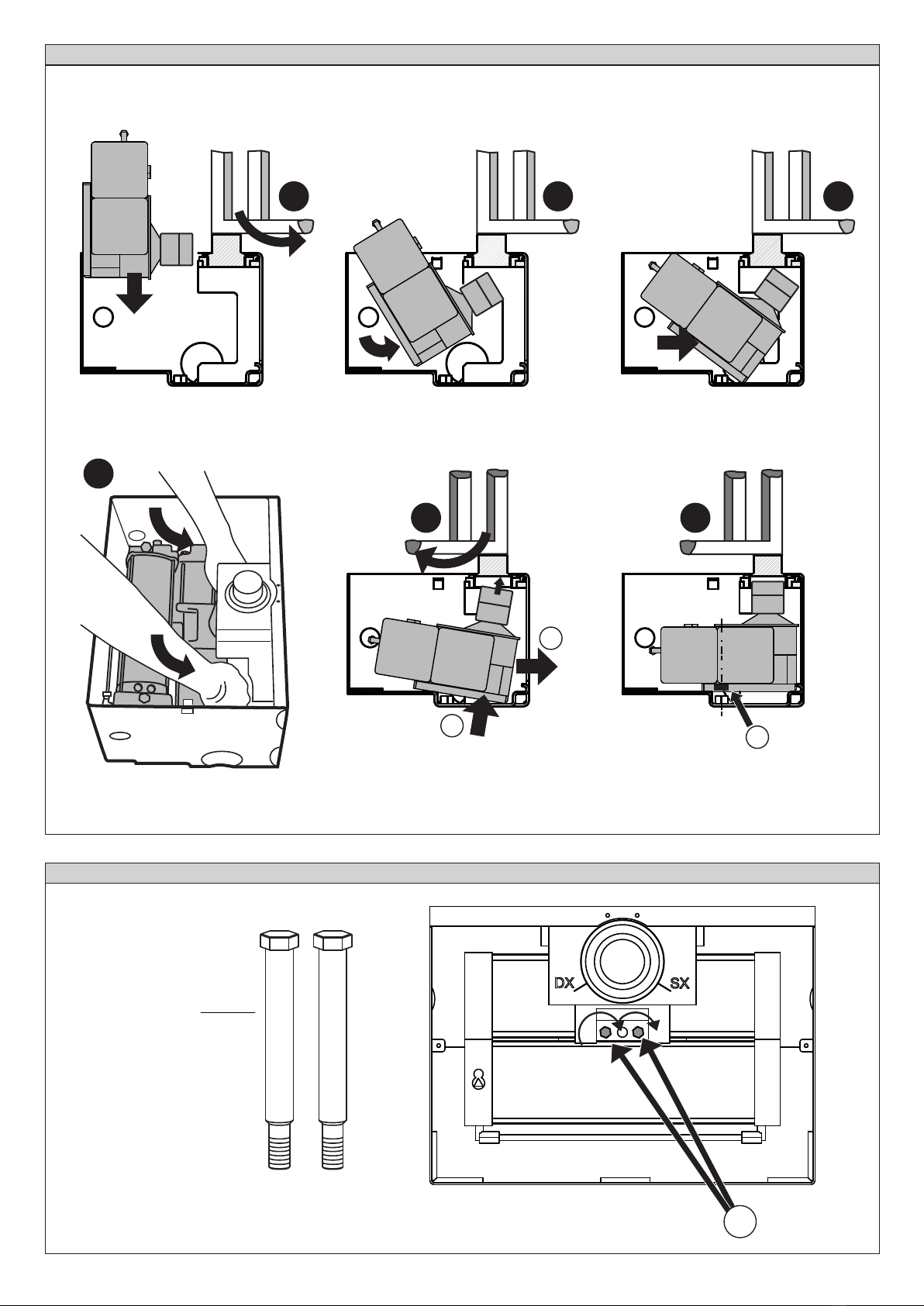
4) MONTAGE DES ANTRIEBES
- Die verzahnte Kupplung auf die Motorwelle montieren (Abb. 4B).
- Den Leitkegel mit den beiden dreizackigen Schrauben M3x8 und
den zugehörigen Unterlegscheiben (Abb. 3) montieren.
- Den Antrieb mit dem zugehörigen Dreiecksschlüssel entsperren
und die Abtriebswelle für die gesamte Wegstrecke in Schließrich-
tung des Flügels bewegen. Um die Motorabtriebswelle zu drehen,
kann ein Rollgabelschlüssel verwendet werden, der an der Ausspa-
rung der verzahnten Kupplung angesetzt wird. In Abb. 4B ist die
Position ausgewiesen, welche die verzahnte Kupplung nach ihrer
Montage an den Antrieb einnehmen muss, je nachdem, ob der Flü-
gel DX oder SX (rechts- oder linksseitig) ist.
- Den Zahn der verzahnten Kupplung in Öffnungsrichtung drehen,
bis er auf einer Achse mit dem Antrieb liegt (Abb. 4C).
- Die Gewindelöcher im Boden des Kastens reichlich einfetten.
- Die Tür so öffnen, dass Platz zum Einsetzen des Antriebs ist (Abb. 5/A).
- Schrauben Sie den Gewindestift M12x20 provisorisch in das zuge-
hörige Gewindeloch, das sich in der verzahnten Kupplung bendet
(Abb. 4C).
- Den Antrieb gemäß den Bewegungen aus Abbildung 5 derart ein-
setzen, dass sich die untere Platte zwischen die Kastenwände ein-
fügt. Führen Sie ihn in die Zwischenstellung aus Abb. 5/C.
- Den Flügel schließen, bis die Kerbe der Buchse in der Mitte liegt, also
auf der Hälfte zwischen den Angaben “Rechts” und “Links”. In dieser
Stellung kann der Zahn der Kupplung in die Buchse eingeführt wer-
den. Falls er nicht sofort passt, bewegen Sie die Tür noch ein wenig.
- Den Antrieb vorne ergreifen, leicht anheben (Abb. 5/D) und in Rich-
tung Anschlag schieben, wie aus Abb. 5/E ersichtlich. Die richtige
Positionierung ist sichergestellt, wenn die Löcher “K” in der Platte
auf einer Linie mit der auf dem Kastenboden angeschweißten Mut-
ter liegen (Abb. 5/F).
- Nun den Gewindestift M12x20 vollständig festziehen.
- Die Schrauben M12x130 in die Löcher “K” einführen und festdrehen (Abb. 6).
- Das Deckelchen verschließen und mit den beiden selbstschneiden-
den Kurzschrauben befestigen, die Abdeckung mit den beiden lan-
gen Schrauben xieren. Den Antrieb anschließen und das System
einer Endabnahme unterziehen.
Lisez attentivement la brochure ”Conseils” et le ”Manuel d’in-
structions” joints, ils fournissent des indications importantes
au sujet de la sécurité, l’installation, l’utilisation et l’entretien.
1) DIMENSIONS (Fig.1)
2) INSTALLATION DE LA CAISSE DE FONDATION
Creuser un trou à la base du pilier, sufsant pour y loger la caisse FCS
(Fig.1). Prévoir un drainage pour l’eau. Réaliser une base en béton
pour poser la caisse de façon à en permettre le réglage (Fig.2).La
caisse doit être positionnée de façon à ce que le centre de la douille
soit parfaitement perpendiculaire à la charnière du vantail. Contrôler
soigneusement l’axe du vantail avec le l à plomb et les deux côtés de
la caisse (Fig.2) avec le niveau. Positionner l’écoulement pour l’eau et
les gaine pour les connexions. Sceller les ssures et les orices inutili-
sés pour ne pas que le ciment non désiré pénètre à l’intérieur.
Remplir le trou. Pour éviter la déformation des parois de la caisse de
fondation pendant la coulée, nous suggérons d’interposer un chevron
en bois.
N.B. Le bord de la caisse doit avancer du niveau du sol pour environ
8-10 mm, ce qui permettra de monter correctement le couvercle.
3) MONTAGE DES VANTAUX
Une fois le béton durci, pour le montage des vantaux il faut procéder
comme suit: lubrier soigneusement la douille et la boucle en bronze.
3.1) Vantail droit (vu de l’intérieur - Fig.4)
- Insérer le manchon « Y » dans le logement prévu à cet effet de la
bague (Fig. 4A).
- Poser le vantail du portail sur la douille en position de PORTAIL
FERME, vérier l’alignement du vantail (douille-charnière vantail)
comme déjà fait pour le positionnement de la caisse.
- Aligner parfaitement le cran de la douille avec l’échancrure “DX” qui
se trouve sur la caisse.
- Effectuer un robuste soudage de la douille au vantail.
3.2) Vantail gauche (vu de l’intérieur - Fig.4)
- Réaliser toutes les opérations du point 3.1 en alignant l’encoche de
la bague avec l’encoche gauche (SX) du caisson.
4) MONTAGE DE L’OPERATEUR
- Monter le joint cannelé sur l’arbre moteur (Fig. 4B).
- Monter le cône avec les deux vis trilobées M3x8 et les rondelles
correspondantes (Fig. 3).
- Débloquer l’opérateur avec la clé triangulaire spéciale et tourner
l’arbre de sortie dans le sens de fermeture de la porte sur toute
la course. Pour tourner l’arbre de sortie du moteur, il est possible
d’utiliser une clé anglaise à insérer sur le creux du joint cannelé.
La position que le joint cannelé doit avoir une fois monté sur l’opé-
rateur, selon que la porte s‘ouvre vers la DX (droite) ou vers la SX
(gauche), est indiquée dans la gure 4B.
- Tourner la dent du joint cannelé dans le sens d’ouverture jusqu’à la
placer dans l’axe avec l’opérateur (Fig.4C).
- Graisser abondamment les trous letés sur le fond du caisson.
- Ouvrir la porte de façon à avoir sufsamment d’espace pour insérer
l’opérateur (Fig. 5/A).
- Visser en partie le goujon M12x20 dans le trou taraudé correspon-
dant se trouvant dans le joint cannelé (Fig. 4C).
- Insérer l’opérateur en respectant les mouvements indiqués dans
la gure 5 de façon à ce que la plaque inférieure s’insère entre les
cloisons du caisson et le placer dans la position intermédiaire de la
gure 5/C.
- Fermer la porte jusqu’à placer l’encoche de la bague au centre,
c’est-à-dire à la moitié entre les indications DX (droite) et SX
(gauche). Dans cette position, il est possible d’enler la dent du
joint dans la bague; si cette dernière ne s’insère pas immédiate-
ment, déplacer encore la porte.
- Soulever légèrement l’automatisme en le prenant par la partie
avant (Fig. 5/D) et le pousser vers la butée comme indiqué dans la
Fig. 5/E. Le positionnement est correct lorsque les trous « K » de la
plaque sont dans l’axe avec l’écrou soudé au fond de la caisse (Fig.
5/F).
- Visser maintenant complètement le goujon M12x20.
- Enler les vis M12x130 dans les trous “K” et les xer (Fig. 6).
- Fermer correctement le petit couvercle en le xant avec les 2 vis
autotaraudeuses courtes et le couvercle avec les 2 longues. Bran-
cher l’opérateur et régler le système.
FCS - Ver. 04 - 3
D811513_03
EP
Lea atentamente el folleto “Advertencias” y el “Manual de
instrucciones” que lo acompañan, pues proporcionan im-
portantes indicaciones referentes a la seguridad, la instalación,
el uso y el mantenimiento.
1) DIMENSIONES (FIG.1)
2) INSTALACION CAJA DE CIMENTACION
Excavar en la base del pilar lo suciente para colocar la caja FCS
(Fig.1). Prever un adecuado drenaje para el agua. Realizar una base
de hormigón donde apoyar la caja de modo que sea posible asentarla
(Fig.2). La caja debe colocarse de manera que el centro del forro se
halle perfectamente en eje con el gozne de la hoja. Controlar atenta-
mente el eje de la hoja con la plomada y los dos lados de la caja con el
nivel, Fig.2. Colocar el tubo de desagñe del agua y los conductos para
las conexiones. Para evitar que entre cemento, cierre las suras y los
agujeros inutilizados. Llenar la excavación de hormigón. Para evitar el
encorvamiento de las paredes de la caja durante la colada, se sugiere
interponer un cabrio de madera.
N.B.: El borde de la caja debe sobresalir aproximadamente 8 - 10 mm.
del nivel del suelo, para poder montar correctamente la tapa.
3) MONTAJE DE LAS HOJAS
Una vez endurecido el hormigón, para el montaje de las hojas hay que
realizar lo siguiente: engrasar atentamente forro de acero y forro de
bronce hacer.
3.1) Hoja derecha (vista desde el interior - Fig.4)
- Inserte el manguito “Y” en el alojamiento del casquillo expresamen-
te previsto (Fig. 4A).
- Apoyar la hoja de la cancela en el forro en posición de CANCE-
LA CERRADA, controlar la alineación de la hoja (forro-gozne hoja)
como ya se ha hecho para la colocación de la caja.
- Alinear perfectamente la muesca del forro con la muesca “DX” pre-
sente en la caja.
- Efectuar una robusta soldadura del casquillo a la hoja.
3.2) Hoja izquierda (vista desde el interior - Fig.4)
- Realice todas las operaciones del punto 3.1 pero alineando la mues-
ca del manguito con la muesca SX de la caja.
4) MONTAJE OPERADOR
- Monte la junta acanalada en el eje motor (Fig. 4B).
- Monte el cono de alojamiento con los dos tornillos trilobulados
M3x8 y las correspondientes arandelas (Fig. 3).
- Desbloquee el operador, con la llave triangular expresamente pre-
vista, y gire el árbol de salida en el sentido de cierre de la hoja
por toda la carrera. Para girar el eje de salida del motor, se puede
utilizar una llave inglesa que se pondrá en la muesca de la junta
acanalada. En la g. 4B, está indicada la posición que la junta aca-
nalada debe tener, una vez montada en el operador, según la hoja
sea DX o SX.
- Gire el diente de la junta acanalada en el sentido de apertura hasta
que quede alineado con el operador (Fig. 4C).
- Engrase abundantemente los agujeros roscados situados en el
fondo de la caja.
- Abra la hoja de manera que haya espacio para introducir el opera-
dor (Fig. 5/A).
- Atornille ligeramente el tornillo sin cabeza M12x20 en el correspon-
diente agujero roscado presente en la junta acanalada (Fig. 4C).
- Introduzca el operador según los movimientos indicados en la -
gura 5, de manera que la placa inferior vaya a insertarse entre las
paredes de la caja, y colóquelo en la posición intermedia de la Fig.
5/C.
- Cierre la hoja hasta colocar la muesca del manguito en el centro,
es decir, a mitad de camino entre las indicaciones DX y SX. En esta
posición, es posible insertar el diente de la junta en el manguito;
en el caso de que este último no se introduzca enseguida, mueva
ulteriormente la hoja.
- Levante ligeramente el operador tomándolo por la parte delantera
(Fig. 5/D) y empújelo hacia el tope como se muestra en la Fig. 5/E.
Se estará seguro de la correcta colocación cuando los agujeros “K”
de la placa quede alineado con las tuercas soldadas en el fondo de
la caja (Fig. 5/F).
- Atornille ahora completamente el tornillo sin cabeza M12x20.
- Inserte los tornillos M12x130 en los agujeros “K” y fíjelo (Fig. 6).
- Cierre la tapa pequeña jándola con los 2 tornillos autorroscantes
cortos y la tapa grande utilizando los 2 tornillos largos. Conecte el
operador y pruebe el sistema.
Leia atentamente o opúsculo “Recomendações” e o “Manual
de instruções” que acompanham este produto, pois que es-
ses fornecem indicações importantes respeitantes a segurança,
a instalação, o uso e a manutenção.
1) DIMENSÕES (FIG.1)
2) INSTALAÇÃO DA CAIXA DE FUNDAÇÃO
Efectuar uma escavação na base do pilar suciente para alojar a caixa
FCS (Fig.1). Executar uma adequada drenagem para a água. Efectuar
uma base de betão para apoiar a caixa de modo a consentir o ajuste
(Fig.2). A caixa deve ser posicionada de maneira que o centro da bu-
cha esteja perfeitamente no eixo com a charneira da folha.
Controlar com atenção o eixo da folha com o o de prumo e com o
nível de bolha em ambos os lados da caixa de fundação (Fig. 2). Po-
sicionar a descarga para a água e as calhas para as conexões. Para
não fazer penetrar cimento indesejado no interior executar o fecho
das aberturas e dos furos inutilizados. Encher a escavação de betão.
Para evitar o encurvamento das paredes da caixa durante a betona-
gem sugerimos de entrepor um puntal de madeira.
N.B. A borda da caixa deve sobressair de aproximadamente 8-10 mm
do nível do pavimento; isto para consentir montar correctamente a
tampa.
3) MONTAGEM DAS FOLHAS
Para a montagem das folhas, com o betão endurecido, executar o se-
guinte: lubricar cuidadosamente com massa a bucha e o casquilho.
3.1) Folha direita (vista do interior - Fig.4)
- Inserir o casquilho “Y” no respectivo alojamento da anilha Fig.4A).
- Apoiar a folha do portão sobre a bucha na posição de PORTÃO
FECHADO, vericar o alinhamento da folha (bucha-charneira folha)
como já foi feito para o posicionamento da caixa.
- Alinhar perfeitamente a marca da bucha com a marca “DTA” presen-
te na caixa.
- Soldar solidamente o anel à folha.
3.2) Folha esquerda (vista do interior - Fig.4)
- Executar todas as operações do ponto 3.1 alinhando porém a mar-
ca da bucha com a marca Esq. (SX) da caixa.
4) MONTAGEM DO OPERADOR
- Montar a ligação estriada no eixo motor (Fig.4B).
- Montar o cone de entalhe com dois parafusos trilobados M3x8 e as
respectivas anilhas (Fig.3).
- Desbloquear o operador com a chave triangular especíca e girar
a árvore de saída no sentido do fecho da folha por todo o percurso.
Para rodar o eixo de saída do motor pode-se utilizar uma chave
inglesa que deve ser introduzida troduza entre as paredes da cai-
xa e colocá-lo na posição intermédia de Fig. 4B. Fechar a folha
até colocar a marca da bucha no centro, isto é a metade entre as
indicações DX e SX.
- Rodar o dente da junta estriada no sentido da abertura até colocá-
-la no eixo com o operador (Fig.4C).
- Lubricar abundantemente os furos roscados no fundo da caixa.
- Abrir a folha de maneira a ter espaço para inserir o operador (Fig.
5/A).
-Aparafusar previamente a cavilha M12x20 no relativo furo roscado
situado na junta estriada (Fig.4A).
- Inserir o operador de acordo com os movimentos indicados na gu-
ra 5 de maneira que a placa inferior se introduza entre as paredes
da caixa e colocá-lo na posição intermédia de Fig. 5/C.
- Fechar a folha até colocar a marca da bucha no centro, isto é a
metade entre as indicações D.TA e ESQ. Nesta posição é possível
introduzir o dente da junta na bucha; no caso em que essa não se
introduza imediatamente mover ulteriormente a folha.
- Levantar ligeiramente o operador pegando-o pela parte dianteira
(Fig.5/D) e empurrá-lo para o batente tal como ilustrado na Fig.
5/E. Tem-se a certeza do correcto posicionamento quando os furos
“K” da placa están em eixo com a porca soldada no fundo da caixa
(Fig. 5/F).
- Aparafusar agora completamente a cavilha M12x20.
- Introduzir os parafusos M12x130 nos furos “K” e xá-los (Fig.6).
- Fechar a tampinha xando-a com os 2 parafusos auto-roscantes
curtos e a tampa com os 2 compridos. Ligar o operador e testar o
sistema.
4-FCS - Ver. 04
D811513_03
200
290
12
30
221
56
200
392
283
ø65
221
94
400
34,5
120
Livello pavimento
Ground level
Niveau du sol
Bodenhöhe
Nivel pavimentacion
Nível do pavimento
8÷10 mm
FIG.1
FIG.2 FIG.3
FCS - Ver. 04 - 5
D811513_03
DX
DX
SX
Destra / Right
Droite / Rechts
Derecha / Direita
DX:
Sinistra / Left
Gauche / Links
Izquierda / Esquerda
SX:
Fig.4
Fig. 4B
Fig. 4C
SX
Fig. 4A
Y
M12x20
6-FCS - Ver. 04
D811513_03
Fig. 6
Fig. 5
M12 x 130
1K
2
AB
E
D
F
C
K
FCS - Ver. 04 - 7
D811513_03
Bft Spa
Via Lago di Vico, 44
36015 Schio (VI)
T +39 0445 69 65 11
F +39 0445 69 65 22
www.bft.it
SPAIN
BFT GROUP ITALIBERICA DE
AUTOMATISMOS S.L.
08401 Granollers - (Barcelona)
www.bftautomatismos.com
FRANCE
AUTOMATISMES BFT FRANCE
69800 Saint Priest
www.bft-france.com
GERMANY
BFT TORANTRIEBSSYSTEME Gmb H
90522 Oberasbach
www.bft-torantriebe.de
UNITED KINGDOM
BFT AUTOMATION UK LTD
Stockport, Cheshire, SK7 5DA
www.bft.co.uk
IRELAND
BFT AUTOMATION LTD
Dublin 12
BENELUX
BFT BENELUX SA
1400 Nivelles
www.bftbenelux.be
POLAND
BFT POLSKA SP. Z O.O.
05-091 ZąBKI
www.bft.pl
CROATIA
BFT ADRIA D.O.O.
51218 Drazice (Rijeka)
www.bft.hr
PORTUGAL
BFT SA-COMERCIO DE
AUTOMATISMOS E MATERIAL DE
SEGURANCIA
3020-305 Coimbra
www.bftportugal.com
CZECH REPUBLIC
BFT CZ S.R.O.
Praha
www.bft.it
TURKEY
BFT OTOMATIK KAPI SISTEMELERI
SANAY VE
Istanbul
www.bftotomasyon.com.tr
RUSSIA
BFT RUSSIA
111020 Moscow
www.bftrus.ru
AUSTRALIA
BFT AUTOMATION AUSTRALIA
PTY LTD
Wetherill Park (Sydney)
www.bftaustralia.com.au
U.S.A.
BFT USA
Boca Raton
www.bft-usa.com
CHINA
BFT CHINA
Shanghai 200072
www.bft-china.cn
UAE
BFT Middle East FZCO
Dubai

Other BFT Enclosure manuals

BFT FCS User manual

BFT

BFT FCS User manual

BFT CPS User manual

BFT

BFT CPS User manual

BFT CPS User manual

BFT

BFT CPS User manual

Popular Enclosure manuals by other brands

Viking VE-9x12 Technical practice

Viking

Viking VE-9x12 Technical practice

Vantec SuperSpeed NexStar 3 user manual

Vantec

Vantec SuperSpeed NexStar 3 user manual

StarTech.com S352BU313R quick start guide

StarTech.com

StarTech.com S352BU313R quick start guide

Pulsar ARADIN2 installation guide

Pulsar

Pulsar ARADIN2 installation guide

fis The Solutionists Z176SFTTX quick start guide

fis The Solutionists

fis The Solutionists Z176SFTTX quick start guide

Code Blue CB 6 Series Administrator's guide

Code Blue

Code Blue CB 6 Series Administrator's guide

Thermaltake Versa T25 TG user manual

Thermaltake

Thermaltake Versa T25 TG user manual

ML Accessories JB55 Installation & maintenance manual

ML Accessories

ML Accessories JB55 Installation & maintenance manual

OSEE 6800N-C2 user manual

OSEE

OSEE 6800N-C2 user manual

Altec Lansing 5194XM CEILING SPEAKER ACCESSORY manual

Altec Lansing

Altec Lansing 5194XM CEILING SPEAKER ACCESSORY manual

Gewiss GW 38 301 manual

Gewiss

Gewiss GW 38 301 manual

Hoffman 4X manual

Hoffman

Hoffman 4X manual

Lian-Li LANCOOL II MESH installation guide

Lian-Li

Lian-Li LANCOOL II MESH installation guide

EFB-Elektronik WGB Series Mounting instructions

EFB-Elektronik

EFB-Elektronik WGB Series Mounting instructions

StarTech.com SAT3510BU3 instruction manual

StarTech.com

StarTech.com SAT3510BU3 instruction manual

HP BladeSystem c7000 Setup and installation guide

HP

HP BladeSystem c7000 Setup and installation guide

LEGRAND CHIEF PAC527L Series installation instructions

LEGRAND

LEGRAND CHIEF PAC527L Series installation instructions

Middle Atlantic Products EWR Series instruction sheet

Middle Atlantic Products

Middle Atlantic Products EWR Series instruction sheet

manuals.online logo
manuals.online logoBrands
  • About & Mission
  • Contact us
  • Privacy Policy
  • Terms and Conditions

Copyright 2025 Manuals.Online. All Rights Reserved.