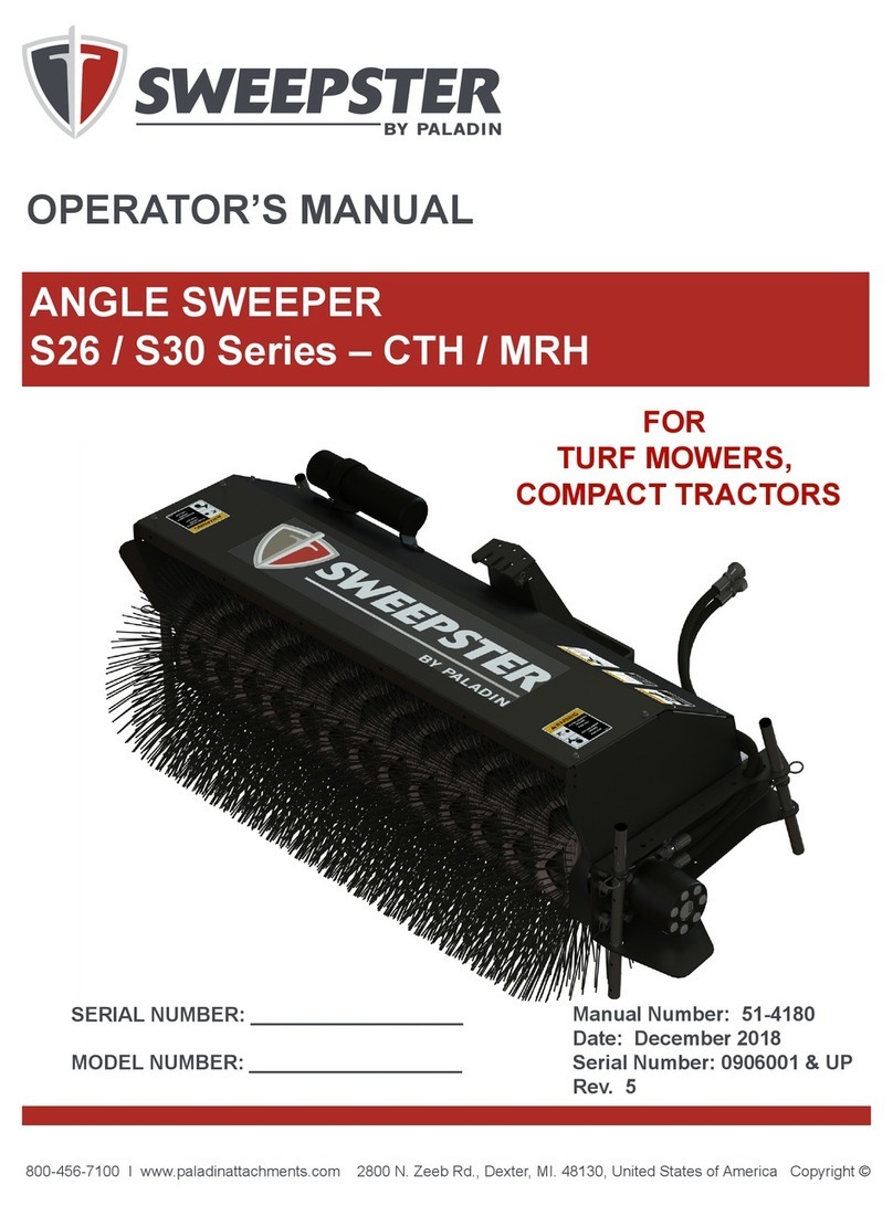
paladin Sweepster M24 Series Product manual

1
51-3000
800-456-7100 I www.paladinattachments.com 2800 N. Zeeb Rd., Dexter, MI. 48130, United States of America Copyright ©
OPERATOR’S AND PARTS MANUAL
M24 Series
L4800, MRM & CTM
Mechanical Windrow Sweepers
Manual Number: 51-3000
Release Date: January 2014
Rev. 1
Serial Number: ___________________
Model Number: ___________________

251-3000
NOTES

3
51-3000
TABLE OF CONTENTS
INTRODUCTION..........................................................................................................................................4
SAFETY STATEMENTS ...............................................................................................................................4
GENERAL SAFETY PRECAUTIONS........................................................................................................5-6
SAFETY SIGNS & LABELS .........................................................................................................................7
INSTALLATION & ADJUSTMENTS.........................................................................................................8-15
OPERATION..........................................................................................................................................16-17
STORAGE ..................................................................................................................................................17
MAINTENANCE ....................................................................................................................................18-21
TROUBLESHOOTING ..........................................................................................................................22-23
BRUSH HEAD ASSEMBLY ...................................................................................................................24-25
DRIVE ASSEMBLIES 1-WAY................................................................................................................26-33
DRIVE ASSEMBLIES 2-WAY................................................................................................................34-43
GEARBOXES........................................................................................................................................44-47
MANUAL ANGLE KIT .................................................................................................................................48
OPTION - DIRT DEFLECTORS ............................................................................................................49-50
OPTION - HYDRAULIC ANGLE KIT .....................................................................................................51-52
OPTION - HYDRAULIC LIFT KITS .......................................................................................................53-56
BOLT TORQUE SPECIFICATIONS ...........................................................................................................57
HYDRAULIC TORQUE SPECIFICATIONS...........................................................................................58-59
GLOSSARY...........................................................................................................................................60-61
WARRANTY ...............................................................................................................................................62

451-3000
INTRODUCTION
Purpose of Sweeper
This sweeper is designed solely for the use in
construction cleanup, road maintenance and similar
operations. Use in any other way is considered
contrary to the intended use. Compliance with and
strict adherence to operation, service and repair
conditions, as specied by the manufacturer, are
also essential elements of the intended use.
Contacting Sweepster
If you have any questions about information in this
manual or need to order parts, please call, write, fax
or e-mail SWEEPSTER.
Sweepster
2800 North Zeeb Road
Dexter, Michigan 48130
Phone: (734)-996-9116 - (800)-456-7100
Fax: (734) 996-9014
e-mail: [email protected]
For help with installation, operation or maintenance
procedures, contact our Technical Service
Department. Direct product questions and parts
orders to our Sales Department.
When ordering parts or accessories, be prepared to
give the following information:
• Sweeper model, serial number and date of
purchase
• Prime mover, make and model
• Part number, description and quantity
Terms Used in Manual
Right-hand, left-hand, front and rear are determined
from the operator’s perspective (either the
operator’s seat or standing behind a walk-behind
unit), facing forward in the normal operating
position.
Warranty
To validate the warranty for this unit, ll out the
warranty card or warranty pages located in the
back of this manual. Then send this information to
SWEEPSTER.
SAFETY STATEMENTS
DANGER! THIS STATEMENT IS USED
WHERE SERIOUS INJURY OR
DEATH WILL RESULT IF THE
INSTRUCTIONS ARE NOT
FOLLOWED PROPERLY.
WARNING! THIS STATEMENT IS USED
WHERE SERIOUS INJURY OR
DEATH COULD RESULT IF
THE INSTRUCTIONS ARE NOT
FOLLOWED PROPERLY.
CAUTION! THIS STATEMENT IS USED
WHERE MINOR INJURY COULD
RESULT IF THE INSTRUCTIONS
ARE NOT FOLLOWED PROPERLY.
NOTICE! THIS STATEMENT IS USED
WHERE EQUIPMENT OR
PROPERTY DAMAGE COULD
RESULT IF THE INSTRUCTIONS
ARE NOT FOLLOWED PROPERLY.
THIS SYMBOL BY ITSELF OR
USED WITH A SAFETY SIGNAL
WORD THROUGHOUT THIS
MANUAL IS USED TO CALL YOUR
ATTENTION TO INSTRUCTIONS
INVOLVING YOUR PERSONAL
SAFETY OR THE SAFETY OF
OTHERS. FAILURE TO FOLLOW
THESE INSTRUCTIONS CAN
RESULT IN INJURY OR DEATH.

5
51-3000
GENERAL SAFETY PRECAUTIONS
WARNING! READ MANUAL PRIOR TO
INSTALL
Improper installation, operation,
or maintenance of this equipment
could result in serious injury or
death. Operators and maintenance
personnel should read this
manual as well as all manuals
related to this equipment and the
prime mover thoroughly before
beginning installation, operation,
or maintenance. FOLLOW ALL
SAFETY INSTRUCTIONS IN
THIS MANUAL AND THE PRIME
MOVERS MANUAL.
WARNING! READ AND UNDERSTAND ALL
SAFETY STATEMENTS
Read all safety decals and safety
statements in all manuals prior
to operating or working on this
equipment. Know and obey all
OSHA regulations, local laws
and other professional guidelines
for your operation. Know and
follow good work practices when
assembling, maintaining, repairing,
mounting, removing or operating this
equipment.
KNOW YOUR EQUIPMENT
Know your equipment’s capabilities,
dimensions and operations before
operating. Visually inspect your
equipment before you start, and
never operate equipment that is not
in proper working order with all safety
devices intact. Check all hardware to
assure it is tight. Make certain that all
locking pins, latches, and connection
devices are properly installed and
secured. Remove and replace any
damaged, fatigued or excessively
worn parts. Make certain all safety
decals are in place and are legible.
Keep decals clean, and replace them
if they become worn and hard to
read.
GENERAL SAFETY PRECAUTIONS
WARNING! PROTECT AGAINST FLYING
DEBRIS
Always wear proper safety glasses,
goggles or a face shield when driving
pins in or out or when operation
causes dust, ying debris, or any other
hazardous material.
WARNING! LOWER OR SUPPORT RAISED
EQUIPMENT
Do not work under raised booms
without supporting them. Do not use
support material made of concrete
blocks, logs, buckets, barrels or any
other material that could suddenly
collapse or shift positions. Make sure
support material is solid, not decayed,
warped, twisted, or tapered. Lower
booms to ground level or onto blocks.
Lower booms and attachments to
the ground before leaving the cab or
operator’s station.
WARNING! USE CARE WITH HYDRAULIC FLUID
PRESSURE
Hydraulic uid under pressure can
penetrate the skin and cause serious
injury or death. Hydraulic leaks
under pressure may not be visible.
Before connecting or disconnecting
hydraulic hoses, read your prime
movers operator’s manual for detailed
instructions on connecting and
disconnecting hydraulic hoses or
ttings.
•Keep unprotected body parts,
such as face, eyes, and arms as far
away as possible from a suspected
leak. Flesh injected with hydraulic
uid may develop gangrene or
other permanent disabilities.
• If injured by injected uid, see a
doctor at once. If your doctor is not
familiar with this type of injury, ask
him to research immediately to
determine proper treatment.

651-3000
WARNING DO NOT MODIFY MACHINE OR
ATTACHMENTS
Modications may weaken the
integrity of the attachment and may
impair the function, safety, life and
performance of the attachment.
When making repairs, use only
the manufacturer’s genuine parts,
following authorized instructions.
Other parts may be substandard
in t and quality. Never modify
any ROPS (Roll Over Protection
System) equipment or device. Any
modications must be authorized in
writing by the manufacturer.
GENERAL SAFETY PRECAUTIONS
CONTINUED
!
WARNING! SAFELY MAINTAIN AND REPAIR
EQUIPMENT
• Do not wear loose clothing, or any
accessories that can catch in
moving parts. If you have long hair,
cover or secure it so that it does
not become entangled in the
equipment.
• Work on a level surface in a well-lit
area.
• Use properly grounded electrical
outlets and tools.
• Use the correct tool for the job at
hand. Make sure they are in good
condition for the task required.
• W e a r t h e p r o t e c t i v e c l o t h i n g
equipment specied by the tool
manufacturer.
WARNING! SAFELY OPERATE EQUIPMENT
Do not operate equipment until you
are completely trained by a qualied
operator in how to use the controls,
know its capabilities, dimensions,
and all safety requirements. See
your prime movers manual for these
instructions.
• Keep all step plates, grab bars,
pedals, and controls free of dirt,
grease, debris, and oil.
• Never allow anyone to be around
the equipment when it is operating.
• Do not allow riders on the
attachment or the prime mover.
• Do not operate the equipment
from anywhere other than the
correct operators position.
• Never leave equipment unattended
with the engine running or with this
attachment in a raise position.
• Do not alter or remove any safety
feature from the prime mover or
this attachment.
• Know your work site safety rules as
well as trafc rules and ow. When
in doubt on any safety issue,
contact your supervisor or safety
coordinator for an explanation.
• Wear safety glasses, protective
clothing, and use a sound piece of
cardboard or wood when
searching for hydraulic leaks.
DO NOT USE YOUR HANDS!
SEE ILLUSTRATION.
GENERAL SAFETY PRECAUTIONS
CONTINUED
WARNING! EXPOSURE TO RESPIRABLE
CRYSTALLINE SILICA
DUST ALONG WITH OTHER
HAZARDOUS DUSTS MAY
CAUSE SERIOUS OR FATAL
RESPIRATORY DISEASE.
It is recommended to use dust
suppression, dust collection and
if necessary personal protective
equipment during the operation of
any attachment that may cause high
levels of dust.

7
51-3000
SAFETY SIGNS & LABELS
There are several specic signs on this sweeper.
The exact location of the hazards and description of
the hazards are reviewed.
Placement or replacement of Safety Signs
1. Clean the area of application with nonammable
solvent, and then wash the same area with soap
and water.
2. Allow the surface to fully dry.
3. Remove the backing from the safety sign,
exposing the adhesive surface.
4. Apply the safety sign to the position shown in
the diagram above and smooth out any bubbles.
Instructions
1. Keep all safety signs clean and legible.
2. Replace all missing, illegible, or damaged safety
signs.
3. Replacement parts, for parts with safety signs
attached, must also have safety signs attached.
4. Safety signs are available, free of charge, from
your dealer.
Item Part Qty Description
1. 50-0147 1 Decal, Frequency of Lube,
Weasler
2. 50-0115 2 Decal, Danger, Rotary
Driveline
3. 50-0236 1 Decal, Gearbox, Hubcity,
Check Oil
4. 50-0721 2 Decal, Warning, Crush point
5. 50-0722 1 Decal, Warning, Misuse
Hazard
6. 50-0726 2 Decal, Warning, Flying
Objects & Entanglement
7. 41043 1 Decal, Warning, Hazardous
dust
1. 50-0147
5. 50-0722
6. 50-0726
4. 50-0721
3. 50-0236
2. 50-0115
2
4
4
5
6
6
2
1
7
3
Serial Tag Location
7. 41043

851-3000
INSTALLATION
gure 1
Mounting Assembly
Install the mounting assembly (gure 1) on the
tractor by the following instructions enclosed with
those parts. Then proceed to Drive Assembly
or Brush Head Assembly if your sweeper has a
mounting assembly that includes a gearbox.
Drive Assembly
NOTE: Some mounting assemblies include a
gearbox. Skip to Installation: Brush Head
Assembly if this applies to your sweeper.
1. Position the drive assembly (gure 1) in front of
the mounting assembly with the gearbox up.
2. Place the rear of the drive assembly on the front
of the mounting assembly. Install a 3/8-16 x 1
1/2 inch cap screw, at washer, lock washer
and nut in the center hole (gure 1), but do not
tighten the hardware completely.
3. Install 2, 3/8-16 x 1 1/2 inch carriage bolts, at
washers, lock washers and nuts in the outer
holes, but do not tighten the hardware.
NOTE: If the mounting assembly includes angles
and an input shield, place angles on the
holes before installing hardware.
4. Connect the input driveline to the tractor
and to the gearbox on the drive assembly.
Follow instructions included with the mounting
assembly.
5. Tighten the cap screw, at washer, lock washer
and nut.
6. Units with input drive shield - Place the input
drive shield (gure 2) over the input driveline.
Attach angle brackets to the input driveline
shield. To make installation easier, put the
washer, lock washer and nut toward the outside
of the shield.

9
51-3000
INSTALLATION
gure 2
gure 3
Brush Head Assembly
1. After installing the mounting and drive
assemblies, position the brush head assembly
(gure 1) in front of the drive assembly.
2. Fasten the brush head assembly to the drive
assembly using 2, 1/2-13 x 1 1/2 inch carriage
bolts, at washers, lock washers and nuts.
Be sure to position the hardware as high as
possible in the slots (gure 2).
3. Connect the output drive shaft to the gearbox
shaft and to sprocket on the right-hand side of
the brush head assembly. Tighten universal joint
set screws.
• If the sweeper has a telescoping drive shaft,
it may need to be cut to length. Be sure to
cut the same amount off both halves.
• If the sweeper has a rectangular drive shaft
and it is too long, shorten it by loosening the
set screw on the universal joint mounted to
the drive assembly gearbox and then sliding
the drive shaft in.
4. Units with rectangular drive shaft - Install the
output driveline shield (gure 2).
a. Place a washer and plastic bushing on the
bolt welded to the output driveline shield.
Place a washer and plastic bushing on the
bolt welded to the gearbox output shield
(gure 2).
b. Insert the bolt on the output driveline shield
through the hole drilled in the chain shield.
Insert the bolt on the gearbox output shield
through the slot on the output driveline
shield.
c. Place a washer and lock nut on both bolts;
tighten.
NOTE: Do not over tighten lock nuts. The shield
must be able to slide back and forth when
the brush head is lowered and raised.

10 51-3000
INSTALLATION
Spring-Chain Assembly, Transport Chain,
Lift Cable
Follow the instructions that match your sweeper.
Spring-Chain Assembly & Transport Chain
Refer to gures 1 and 2.
1. Connect 2, 26-link chains and 2 springs to form
a loop.
2. Place chains in the outside slots in the drive
assembly upright and in the brush head
assembly upright.
3. Place the 36-link transport chain in the center
slot in the drive assembly and in the brush head
assembly upright.
4. Slide a pin in the holes under the drive assembly
upright and a pin in the holes under the brush
head assembly. Insert a hairpin clip in each pin.
Spring-Chain Assembly & Lift Cable
Refer to gures 3 & 4.
1. Connect 2, 26-link chains and 2 springs to form
a loop.
2. Place chains in the outside slots in the drive
assembly upright and in the brush head
assembly upright.
3. Route 1 end of the lift cable through the chain
link welded to the brush head assembly upright.
Loop the loose end around and secure it with a
cable clamp (gure 5).
CAUTION! INSTALL CABLE CLAMPS AS
SHOWN IN FIGURE 5; otherwise;
the cable could slip, possibly
damaging the sweeper or injuring the
operator.
4. Loop the other end through the link on the drive
assembly upright; secure it with a cable clamp.
5. Hook up the electric lift system or optional
hydraulic lift system.
gure 1
gure 2
gure 3

11
51-3000
INSTALLATION
6. Raise the brush head assembly using the lift
system. If the brush head assembly raises 4
inches (101mm) off the ground, the lift cable
is properly adjusted; otherwise, go to the next
step.
7. Adjust the cable.
• If the brush head assembly does not raise
enough, decrease the amount of cable
between the uprights.
• If the brush head assembly raises too much,
increase the amount of cable between the
uprights.
Spring-Chain Assembly, Transport Chain & Lift Cable
Refer to gures 6 & 7.
1. Connect 2, 26-link chains and 2 springs to form
a loop.
2. Place chains in the outside slots in the drive
assembly upright and in the brush head
assembly upright.
3. Route 1 end of the lift cable through the chain
link welded to the brush head assembly upright.
Loop the loose end around and secure it with a
cable clamp (gure 5).
CAUTION! INSTALL CABLE CLAMPS AS
SHOWN IN FIGURE 5; otherwise;
the cable could slip, possibly
damaging the sweeper or injuring the
operator.
4. Loop the other end through the link on the drive
assembly upright; secure it with a cable clamp.
5. Place the 36-link transport chain in the center
slot in the drive assembly and in the brush head
assembly upright.
6. Slide a pin in the holes under the drive assembly
upright and a pin in the holes under the brush
head assembly. Insert a hairpin clip in each pin.
7. Hook up the electric lift system or optional
hydraulic lift system.
gure 4
gure 5
gure 6
gure 7

12 51-3000
INSTALLATION
8. Raise the brush head assembly using the lift
system. If the brush head assembly raises 4
inches (101mm) off the ground, the lift cable
is properly adjusted; otherwise, go to the next
step.
9. Adjust the cable.
• If the brush head assembly does not raise
enough, decrease the amount of cable
between the uprights.
• If the brush head assembly raises too much,
increase the amount of cable between the
uprights.
Spring Chain Assemblies & Lift Cable
Refer to gures 1 & 2.
1. Attach a spring to 1 end of each chain.
2. Hook the springs on the drive assembly upright.
3. Place chains on the brush head assembly
upright using the outside slots. Slide a pin in the
holes under the drive assembly upright to secure
the spring-chain assemblies; insert a hairpin clip
in the pin.
4. Route 1 end of the lift cable through the chain
link welded to the brush head assembly upright.
Loop the loose end around and secure it with a
cable clamp (gure 3).
CAUTION! INSTALL CABLE CLAMPS AS
SHOWN IN FIGURE 5; otherwise;
the cable could slip, possibly
damaging the sweeper or injuring the
operator.
5. Loop the other end through the link on the drive
assembly upright; secure it with a cable clamp.
6. Hook up the electric lift system or optional
hydraulic lift system.
7. Raise the brush head assembly using the lift
system. If the brush head assembly raises 4
inches (101mm) off the ground, the lift cable
is properly adjusted; otherwise, go to the next
step.
gure 1
gure 2
gure 3
gure 4

13
51-3000
INSTALLATION
gure 5
gure 6
To Actuator (R ed)
To Actuator (Yellow )
To Powe
r
(R ed)
To Ground
(Yellow )
To Actuator (Yellow)
To Actuator (Red)
To Ground
(Yellow)
8. Adjust the cable.
• If the brush head assembly does not raise
enough, decrease the amount of cable
between the uprights.
• If the brush head assembly raises too much,
increase the amount of cable between the
uprights.
Spring-Chain Assembly & Standard Hydraulic Lift
Figure 4 shows assemblies fully installed.
1. Connect 2, 26-link chains and 2 springs to form
a loop (gure 5).
2. Place chains in the outside slots in the drive
assembly upright and in the brush head
assembly upright.
3. Attach adapter ttings to both cylinder ports, and
install elbow ttings on adapter ttings. Then,
attach hoses to the elbow ttings and install
quick coupler ttings on the hoses.
4. Place a shackle on the rod end of the cylinder;
then, attach the shackle to the brush frame
upright.
5. Place a shackle on the barrel end of the cylinder
and attach the chain to the shackle. Then, attach
the chain to the center slot in the drive mounting
assembly upright.
6. Connect quick coupler ttings to the front remote
hydraulic outlets on the tractor.
7. Completely collapse the cylinder to check for
adjustment.
• If the brush head assembly lifts 4 inches
(101mm) off the ground, the hydraulic lift is
properly adjusted.
• If the brush head assembly does not lift 4
inches (101mm) off the ground, adjust the
chain. To raise the brush head assembly
more, shorten the chain length between
the cylinder and upright. To lower the brush
head assembly, add to the chain length.
Electric Lift System
NOTE: Sweepers for commercial turf tractors and
those with the hydraulic lift option do not
use an electric lift system.
1. Locate a convenient, open area on the tractor
dash to mount the lift switch.
NOTICE! AVOID DAMAGE TO THE PRIME
MOVER. Before drilling, check
behind the tractor dash to make sure
that you will not drill into any wires or
other objects.
2. Use a center punch to mark the lift switch
location. Drill a pilot hole with a 1/4 inch bit;
then, drill the nish hole with a 1/2 inch bit.
3. Insert the switch and secure it with a nut.
4. Route the control wires and connector to the
front of the tractor. If necessary, strap or tape
wires to the tractor frame to prevent them from
hanging down.
To Power
(Red)

14 51-3000
INSTALLATION / ADJUSTMENTS
NOTICE! AVOID WIRE DAMAGE. Keep wires
away from hot and/or moving parts.
5. Connect the red wire to the tractor power supply.
Connect the yellow wire to a good ground,
preferably the battery ground or tractor frame
(gure 6).
NOTICE! AVOID DAMAGE TO THE
ELECTRIC LIFT SYSTEM. Add a 13-
amp, 12-volt fuse in line if the power
supply is not fused.
6. Connect the wires from the lift switch to the
actuator.
NOTE: If it is necessary to replace a wire, use a
14-gauge or heavier wire.
Leveling
Level the sweeper after installation and before each
use for even brush wear and efcient sweeping.
1. Drive the sweeper to a level, paved area.
2. Lower the brush head assembly into the
sweeping position. Make sure the weight of the
brush head assembly is on the spring-chain
assemblies and the brush just touches the
ground.
3. Level the drive assembly using a level (gure 1).
• If the front of the drive assembly is high, turn
the leveling screws out (to the left) to lower
it.
• If the front of the drive assembly is low, turn
the leveling screws out (to the left) to raise it.
See gure 2 for leveling screw locations.
4. With the brush head assembly in the straight
position, measure from each end of the brush
frame to the ground.
5. Compare measurements.
• If they are not equal, slide the low side of the
brush head assembly up in the slots on the
drive assembly. Repeat steps 4 and 5 until
gure 1
gure 2
gure 3
gure 4
High High
High High
Low Low
Low Low
Leveling Screws
Angled
Angled
Angled
Angled
Left
Left
Right
Right

15
51-3000
ADJUSTMENTS
gure 5
gure 6
Spring-Chain
Assembly Brush Head
Upright
Transport Chain
Drive Assembly
Upright
Swept Area
2-3 Inches
(51-76mm)
the measurements are equal. Tighten the
hardware.
• If they are equal, go to step 6 (2-way
sweepers) or the sweeper is level (1-way
sweepers).
6. 2-way sweepers only - Swing the brush head
assembly to the right. Measure from each end of
the brush frame to the ground. Then, swing the
brush head assembly to the left. Measure from
each end of the brush frame to the ground.
• If all 4 measurements are the same, the
brush head assembly is level.
• If the measurements are not equal, refer to
gures 3 and 4 for adjustments.
Repeat step 6 until the brush head assembly is
level.
Brush Pattern
A properly adjusted brush offers the best sweeper
performance. To check brush pattern:
1. Move the sweeper to a dusty, at surface.
2. Set the prime mover’s parking brake and leave
the engine running.
3. Start the sweeper at a slow speed; then,
lower it so bristle tips touch the ground. Run
the sweeper in a stationary position for 10-30
seconds.
4. Raise the sweeper and back away; switch off
the sweeper and engine and remove the key.
The brush pattern left in the dust should be 2-3
inches (51-76mm) wide, running the length of
the
brush. Compare the swept area with gure 5.
5. Adjust the brush pattern as necessary.
a. Raise the brush head assembly with the
electric lift system, optional hydraulic lift
system or manually.
WARNING! AVOID SERIOUS INJURY OR
DEATH. Do not allow anyone to
go near or touch the brush head
assembly while the sweeper is
running. Always stop the sweeper,
shut off the prime mover engine and
remove the key rst.
b. Adjust the spring-chain assembly (gure 6).
• If the pattern is too wide, decrease the
number of links between the uprights.
• If the pattern is too narrow, increase the
number of links between the uprights.
Transport Chain
The transport chain supports the weight of the brush
head during transport between work sites.
1. Raise the sweeper.
2. Tighten the transport chain (gure 6)
3. Lower the sweeper so the transport chain
supports the weight of the sweeper.

16 51-3000
OPERATION
Before each use
Preform daily maintenance as indicted in
Maintenance: Schedule.
Run the prime mover and sweeper at a slow idle.
Check for loose hardware or other problems and
make corrections, if necessary, before using the
sweeper.
WARNING! AVOID SERIOUS INJURY. Check
for objects that could harm the
operator or others if thrown by the
sweeper. Remove items before
sweeping.
Observe wind direction. Sweeping with the wind
makes sweeping more effective and helps keep
debris off the operator.
Directing Debris
Direct debris by angling the brush head in that
direction.
The terms swing and angle are used
interchangeably.
Manual Angle Kit with Tube Links
1. Remove the lock pin from links.
2. Position the brush head at the desired angle,
aligning holes in the inner and outer link.
3. Insert and close the lock pin.
Manual Angle Kit with T-Pin
1. Pull up on the T-pin.
2. Position the brush head at the desired angle.
3. Allow the pin to spring back into place.
Optional Hydraulic Angle Kit
1. Start the prime mover.
2. Position the brush head at the desired angle by
using the valve control for swing function.
Sweeping
To sweep:
1. Manual Angle Kit Only - Swing the brush head
assembly the direction that you want to direct
debris.
2. Start the prime mover at idle.
3. Engage the PTO.
4. Hydraulic Angle Kit Only - Swing the brush head
assembly the direction that you want to direct
debris.
5. Lower the brush to the ground.
6. Increase prime mover engine rpm to sweeping
speed.
NOTICE! AVOID DAMAGE TO THE PRIME
MOVER PTO. Do not run the engine
at speeds which make the PTO
run faster than the recommended
speed marked on the prime mover’s
tachometer.
7. Travel forward at 5mph (8kph) or less.
At the end of a run: slow engine and travel
speeds, disengage the brush, raise the brush
head assembly and then make the turn.
NOTICE! AVOID SWEEPER DAMAGE. When
approaching obstacles, like utility
poles or re hydrants, slow engine
and travels to avoid hitting these
hazards.

17
51-3000
OPERATION
Operating Tips
NOTICE! AVOID SWEEPER DAMAGE. Do not
ram into piles. Use a dozer blade for
this type of job.
Brush, Engine, & Travel Speeds
Vary brush, engine and travel speeds to match
sweeping conditions.
Large areas
When sweeping a large area, such as a parking lot,
make a path down the middle and sweep to both
sides. This reduces the amount of debris that the
sweeper must sweep in the next pass.
Snow
Fast brush speeds and slow travel speeds are
needed to sweep snow effectively. Start at 3/4
throttle and the lowest gear of the prime mover.
For wet and/or deep snow, increase to almost full
throttle. This helps keep snow from packing up
inside the brush hood.
In deep snow you may need to make multiple
passes to get down to a clean surface.
To keep snow from blowing back onto a swept area,
always sweep so the wind is at your back or so it
follows the brush angle.
Dirt & Gravel
To keep dust at a minimum, plan sweeping for days
when it is overcast and humid or after it has rained.
Also, sweep so the wind blows at your back or in the
direction the brush head is angled.
Low brush speeds and moderate travel speeds work
best for cleaning debris from hard surfaces. Brush
speeds that are too fast tend to raise dust because
of the aggressive sweeper action.
To sweep gravel, use just enough brush speed to
“roll” the gravel, not throw it.
Heavy Debris
Travel slowly - less than 5mph (8kph)
Sweep a path less than the full width of the
sweeper.
Increase engine speed if debris becomes very
heavy.
Thatch
Low brush speeds and low prime mover speeds do
the best thatching job.
To prevent the brush from pulling itself into the
ground, adjust the spring-chain assembly so the
bristle tips barely touch the grass.
If the brush pulls into the grass and stalls while
sweeping, use the lift to raise the brush. Do not
increase throttle to override a stall out.
Use a combination of brush speeds and ground
speeds that rolls up a neat windrow.
To keep thatch from blowing back onto a swept
area, sweep with the wind at your back or in the
direction the brush is angled.
STORAGE
Brushes
NOTICE! DO NOT STORE THE SWEEPER
WITH WEIGHT ON THE
BRUSH. Weight will deform the
bristles, destroying the sweeping
effectiveness. To avoid this problem,
place the sweeper on blocks or use
optional stands.
Do not store polypropylene brushes
in direct sunlight. The material can
deteriorate and crumble before the
bristles are worn out.
Keep polypropylene brush material
away from intense heat or ame.

18 51-3000
MAINTENANCE
Maintenance Record
Use this log to record maintenance performed on the sweeper.
Date Maintenance Procedure
Performed
Performed by Comments

19
51-3000
MAINTENANCE
Schedule
Part Schedule
Daily Every 8
Hours
Every 40
Hours
When
Necessary
Brush Head Assembly - Check brush pattern; adjust
as necessary. (See Adjustments: Brush Height) Level
brush head. (See Adjustments: Leveling)
Drive Chain - Lubricate with oil or chain lubricant.
Drive Shaft - Lubricate universal joints with high-
quality grease. Tighten universal joint set screws.
Electric Lift System - Inspect wires. Apply silicon
spray to connections.
Gearbox - Check oil level; ll with SAE 80-90 weight
oil. Inspect for oil leaks. Check end play in shafts.
Clean shafts and vent plugs.
Hardware - Check for and tighten loose hardware.
Hydraulic Lift Option - Inspect hydraulic hoses and
connections. Replace damaged or worn parts.
Mounting Assembly - Lubricate with high-quality
grease.
Safety Signs - Clean to keep instructions readable.
Swing Plate - Lubricate with high-quality grease.
Tractor Air Cleaner - Clean or replace according to
instructions in tractor’s owner’s manual.
V-Belt - Check tension. Replace ant worn belts.
General
For best performance, regularly maintain your
sweeper. Carefully follow recommendations listed in
this manual.
Lubricating Constant Velocity (CV) Drive Shaft
Lubricate with high-quality grease before starting
work and after every 8 hours.
Clean and grease the drive shaft before each period
of non-use.
To prevent freezing in winter, grease the shield
tubes.
Lubricating Gearbox
After the rst 100 operating hours, drain the oil and
ush the gearbox with an approved, nonammable,
nontoxic solvent. Rell with oil.
Following the rst oil change, oil after every 2,500
operating hours or 6 months, whichever comes rst.

20 51-3000
MAINTENANCE
gure 1
gure 2
gure 3
Replacing Brush Sections
1. Remove the front bolt from inside the right-
hand side of the brush frame. This allows you
to remove the shield and right mounting bracket
(gure 1).
2. Remove the rear screw from the right-hand side
of the brush frame.
3. Remove the 2 bolts from inside the left-hand
side of the brush frame (gure 2).
4. Pull the brush out of the brush frame.
5. Stand the brush on end and rest it on blocks.
6. Loosen screws on the retainer plate and take off
the retainer halves (gure 3).
7. Remove old sections from the core.
8. Install new sections by doing the following:
a. Number the tubes on the core as 1, 2 and 3
(gure 4).
b. Slide the rst section onto the core with the
drive pins on both sides of tube 1. Make sure
that drive pins (gure 5) face up.
NOTE: When using 1/2 poly - 1/2 wire sections,
placeapolysectionrstandlaston
the core to prevent damage to the
hood, driveline and frame.
c. Place the second section on the core with
drive pins on both sides of tube 2. Be sure
drive pins face down.
d. Slide the third section onto the core with
drive pins around tube 3. Be sure the drive
pins face up.
e. Slide sections on until the core is full, making
sure to alternate the tubes used and the
direction of the drive pins.
Front Bolt
This manual suits for next models
3
Table of contents
Other paladin Blower manuals
Popular Blower manuals by other brands

Giant-Vac
Giant-Vac Whisper-Jet 60BWJ Assembly instructions operator's manual parts list

Toro
Toro Flex-Force Power System 51822 Operator's manual

FXA
FXA FXAJD5803 instruction manual

Nilfisk-Advance
Nilfisk-Advance RS 501 user manual

Echo
Echo PB-413H - PARTS CATALOG SERIAL NUMBER P06413001001 -... parts catalog

Clemas & Co
Clemas & Co S3 Operator's manual