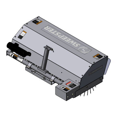
paladin Sweepster S26 Series User manual

ANGLE SWEEPER
S26 / S30 Series – CTH / MRH
800-456-7100 I www.paladinattachments.com 2800 N. Zeeb Rd., Dexter, MI. 48130, United States of America Copyright ©
SERIAL NUMBER: ___________________
MODEL NUMBER: ___________________
FOR
TURF MOWERS,
COMPACT TRACTORS
OPERATOR’S MANUAL
Manual Number: 51-4180
Date: December 2018
Serial Number: 0906001 & UP
Rev. 5


3
51-4180
TABLE OF CONTENTS
PREFACE.............................................................................................................................................. 5
SAFETY PRECAUTIONS
Safety Statements ..................................................................................................................... 6
General Safety Precautions.................................................................................................... 6-8
Equipment Safety Precautions ............................................................................................. 9-10
DECALS......................................................................................................................................... 11-12
INSTALLATION
Installation........................................................................................................................... 13-15
Electric Lift Installation............................................................................................................. 16
MRH Power Pack .................................................................................................................... 17
Pump & Hoses.................................................................................................................... 17-18
Detaching................................................................................................................................. 18
OPERATION
Intended Use ........................................................................................................................... 19
Controls ................................................................................................................................... 19
Before Operating ..................................................................................................................... 19
Operation................................................................................................................................. 20
Brush Pattern Adjustment........................................................................................................ 21
Transport Chain ....................................................................................................................... 21
Operating Tips ......................................................................................................................... 22
Storage / Removal From Storage............................................................................................ 23
Lift Points ................................................................................................................................ 24
Tie Down Points / Transporting................................................................................................ 25
MAINTENANCE
Routine Maintenance............................................................................................................... 26
Leveling ................................................................................................................................... 27
Replacing Brush Sections........................................................................................................ 28
TROUBLESHOOTING................................................................................................................... 29-34
SPECIFICATIONS
SweeperSpecications ........................................................................................................... 35
BoltTorqueSpecications ....................................................................................................... 36
PARTS / WARRANTY......................................................................................................................... 37

51-4180
4
THIS PAGE
IS INTENTIONALLY
BLANK

5
51-4180
PREFACE
10344 1-31-17-5
GENERAL COMMENTS
Congratulations on the purchase of your new product! This product was carefully designed
and manufactured to give you many years of dependable service. Only minor maintenance (such
as cleaning and lubricating) is required to keep it in top working condition. Be sure to observe all
maintenance procedures and safety precautions in this manual and on any safety decals located
on the product and on any equipment on which the attachment is mounted.
This manual has been designed to help you do a better, safer job. Read this manual care-
fully and become familiar with its contents.
WARNING! Never let anyone operate this unit without reading the "Safety Precautions"
and "Operating Instructions" sections of this manual.
Always choose hard, level ground to park the vehicle on and set the brake
so the unit cannot roll.
Unless noted otherwise, right and left sides are determined from the operator’s control posi-
tion when facing forward.
NOTE: The illustrations and data used in this manual were current (according to the infor-
mation available to us) at the time of printing, however, we reserve the right to redesign and
change the attachment as may be necessary without notication.
BEFORE OPERATION
The primary responsibility for safety with this equipment falls to the operator. Make sure the
equipment is operated only by trained individuals that have read and understand this manual. If
there is any portion of this manual or function you do not understand, contact your local authorized
dealer or the manufacturer to obtain further assistance. Keep this manual available for reference.
Provide the manual to any new owners and/or operators.
SAFETY ALERT SYMBOL
This is the “Safety Alert Symbol” used by this industry. This symbol is used to warn
of possible injury. Be sure to read all warnings carefully. They are included for your
safety and for the safety of others working with you.
SERVICE
Use only manufacturer replacement parts. Substitute parts may not meet the required stan-
dards.
Record the model and serial number of your unit on the cover of this manual. The parts
department needs this information to insure that you receive the correct parts.
SOUND AND VIBRATION
Sound pressure levels and vibration data for this attachment are inuenced by many dierent param-
eters: some items are listed below (not inclusive):
• prime mover type, age, condition, with or without cab enclosure and conguration
• operator training, behavior, stress level
• job site organization, working material condition, environment
Based on the uncertainty of the prime mover, operator, and job site, it is not possible to get precise ma-
chine and operator sound pressure levels or vibration levels for this attachment.
NOTE:Alist of all Paladin Patents can be found at http://www.paladinattachments.com/patents.asp.

51-4180
6
SAFETY STATEMENTS
DANGER
GENERAL SAFETY PRECAUTIONS
WARNING! READ MANUAL PRIOR TO INSTALLATION
Improper installation, operation, or maintenance of this equipment could result in
serious injury or death. Operators and maintenance personnel should read this man-
ual, as well as all manuals related to this equipment and the prime mover thoroughly
before beginning installation, operation, or maintenance. FOLLOW ALL SAFETY
INSTRUCTIONS IN THIS MANUAL AND THE PRIME MOVER’S MANUAL(S).
READ AND UNDERSTAND ALL SAFETY STATEMENTS
Read all safety decals and safety statements in all manuals prior to operating or
working on this equipment. Know and obey all OSHA regulations, local laws, and
other professional guidelines for your operation. Know and follow good work
practices when assembling, maintaining, repairing, mounting, removing, or operating
this equipment.
KNOW YOUR EQUIPMENT
Know your equipment’s capabilities, dimensions, and operations before operating.
Visually inspect your equipment before you start, and never operate equipment that
is not in proper working order with all safety devices intact. Check all hardware to
ensure it is tight. Make certain that all locking pins, latches, and connection devices
are properly installed and secured. Remove and replace any damaged, fatigued, or
excessively worn parts. Make certain all safety decals are in place and are legible.
Keep decals clean, and replace them if they become worn or hard to read.
WARNING
CAUTION
NOTICE
THIS SIGNAL WORD INDICATES A HAZARDOUS SITUATION WHICH, IF
NOT AVOIDED, WILL RESULT IN DEATH OR SERIOUS INJURY.
THIS SIGNAL WORD INDICATES A HAZARDOUS SITUATION WHICH, IF
NOT AVOIDED, COULD RESULT IN DEATH OR SERIOUS INJURY.
THIS SIGNAL WORD INDICATES A HAZARDOUS SITUATION WHICH, IF
NOT AVOIDED, COULD RESULT IN MINOR OR MODERATE INJURY.
NOTICE IS USED TO ADDRESS PRACTICES NOT RELATED TO PHYSICAL
INJURY.
THIS SYMBOL BY ITSELF OR WITH A WARNING WORD THROUGHOUT THIS
MANUAL IS USED TO CALL YOUR ATTENTION TO INSTRUCTIONS INVOLVING
YOUR PERSONAL SAFETY OR THE SAFETY OF OTHERS. FAILURE TO FOLLOW
THESE INSTRUCTIONS CAN RESULT IN INJURY OR DEATH.

7
51-4180
GENERAL SAFETY PRECAUTIONS
WARNING! PROTECT AGAINST FLYING DEBRIS
Always wear proper safety glasses, goggles, or a face shield when driving pins in or
out,orwhenanyoperationcausesdust,yingdebris,oranyotherhazardousmate-
rial.
WARNING! LOWER OR SUPPORT RAISED EQUIPMENT
Do not work under raised booms without supporting them. Do not use support mate-
rial made of concrete blocks, logs, buckets, barrels, or any other material that could
suddenly collapse or shift positions. Make sure support material is solid, not de-
cayed, warped, twisted, or tapered. Lower booms to ground level or on blocks. Lower
booms and attachments to the ground before leaving the cab or operator’s station.
WARNING! USE CARE WITH HYDRAULIC FLUID PRESSURE
Hydraulicuidunderpressurecanpenetratetheskinandcauseseriousinjuryor
death. Hydraulic leaks under pressure may not be visible. Before connecting or dis-
connecting hydraulic hoses, read your prime mover’s operator’s manual for detailed
instructionsonconnectinganddisconnectinghydraulichosesorttings.
•Keep unprotected body parts, such as face, eyes, and arms as far away as
possiblefromasuspectedleak.Fleshinjectedwithhydraulicuidmaydevelop
gangrene or other permanent disabilities.
• Ifinjuredbyinjecteduid,seeadoctoratonce.Ifyourdoctorisnotfamiliarwith
this type of injury, ask him to research it immediately to determine proper treat-
ment.
• Wear safety glasses, protective clothing, and use a piece of cardboard or wood
when searching for hydraulic leaks. DO NOT USE YOUR HANDS!
SEE ILLUSTRATION.
CARDBOARD
HYDRAULIC HOSE
OR FITTING
MAGNIFYING GLASS

51-4180
8
GENERAL SAFETY PRECAUTIONS
WARNING! DO NOT MODIFY MACHINE OR ATTACHMENTS
Modicationsmayweakentheintegrityoftheattachmentandmayimpairthefunc-
tion, safety, life, and performance of the attachment. When making repairs, use only
themanufacturer’sgenuineparts,followingauthorizedinstructions.Otherpartsmay
besubstandardintandquality.NevermodifyanyROPS(RollOverProtective
Structure)orFOPS(FallingObjectProtectiveStructure)equipmentordevice.Any
modicationsmustbeauthorizedinwritingbythemanufacturer.
WARNING! SAFELY MAINTAIN AND REPAIR EQUIPMENT
•Do not wear loose clothing or any accessories that can catch in moving parts. If
you have long hair, cover or secure it so that it does not become entangled in the
equipment.
• Work on a level surface in a well-lit area.
• Use properly grounded electrical outlets and tools.
• Use the correct tools for the job at hand. Make sure they are in good condition for
the task required.
• Weartheprotectiveequipmentspeciedbythetoolmanufacturer.
SAFELY OPERATE EQUIPMENT
Donotoperateequipmentuntilyouarecompletelytrainedbyaqualiedoperator
in how to use the controls, know its capabilities, dimensions, and all safety require-
ments. See your machine’s manual for these instructions.
•Keep all step plates, grab bars, pedals, and controls free of dirt, grease, debris,
and oil.
• Never allow anyone to be around the equipment when it is operating.
• Do not allow riders on the attachment or the prime mover.
• Do not operate the equipment from anywhere other than the correct operator’s
position.
• Never leave equipment unattended with the engine running, or with this attach-
ment in a raised position.
• Do not alter or remove any safety feature from the prime mover or this attach-
ment.
• Knowyourworksitesafetyrulesaswellastrafcrulesandow.Whenindoubt
on any safety issue, contact your supervisor or safety coordinator for an explana-
tion.
WARNING! CALIFORNIA PROPOSITION 65 WARNING.
This product may contain a chemical known to the state of California to cause
cancer, or birth defects or other reproductive harm. www.P65Warnings.ca.gov

9
51-4180
EQUIPMENT SAFETY PRECAUTIONS
WARNING! KNOW WHERE UTILITIES ARE
Observe overhead electrical and other utility lines. Be sure equipment will clear
them. When digging, call your local utilities for location of buried utility lines, gas,
water,andsewer,aswellasanyotherhazardyoumayencounter.
WARNING! EXPOSURE TO RESPIRABLE CRYSTALLINE SILICA DUST
ALONG WITH OTHER HAZARDOUS DUSTS MAY CAUSE
SERIOUS OR FATAL RESPIRATORY DISEASE.
It is recommended to use dust suppression, dust collection and if necessary
personal protective equipment during the operation of any attachment that may
cause high levels of dust.
WARNING! REMOVE PAINT BEFORE WELDING OR HEATING
Hazardousfumes/dustcanbegeneratedwhenpaintisheatedbywelding,soldering
or using a torch. Do all work outside or in a well ventilated area and dispose of paint
and solvent properly. Remove paint before welding or heating.
When sanding or grinding paint, avoid breathing the dust. Wear an approved
respirator. If you use solvent or paint stripper, remove stripper with soap and water
before welding. Remove solvent or paint stripper containers and other flammable
material from area. Allow fumes to disperse at least 15 minutes before welding or
heating.
WARNING! END OF LIFE DISPOSAL
At the completion of the useful life of the unit, drain all fluids and dismantle by
separatingthedifferentmaterials(rubber,steel,plastic,etc.).Followallfederal,state
and local regulations for recycling and disposal of the fluid and components.
OPERATING THE SWEEPER
• Do not exceed the lifting capacity of your prime mover.
• Operate only from the operator’s station.
• When traveling on rough terrain, reduce speed to avoid “bouncing” the sweeper.
Loss of steering can result.
• When operating on slopes, drive up and down, not across. Avoid steep hillside
operation, which could cause the prime mover to overturn.
• Reduce speed when driving over rough terrain, on a slope, or turning, to avoid
overturning the vehicle.
• An operator must not use drugs or alcohol, which can change his or her alertness
or coordination. An operator taking prescription or over-the-counter drugs should
seek medical advice on whether or not he or she can safely operate equipment.
• Before exiting the prime mover, lower the attachment to the ground, apply the
brakes, turn off the prime mover’s engine and remove the key.
• Never lift the lowest portion of the attachment plate higher than 5’ above
the ground.
• Do not lock the auxiliary hydraulics of your prime mover in the “ON” position.

51-4180
10
EQUIPMENT SAFETY PRECAUTIONS
TRANSPORTING THE SWEEPER
• Travel only with the attachment in a safe transport position to prevent uncon-
trolled movement. Drive slowly over rough ground and on slopes.
• When transporting on a trailer: Secure attachment at recommended tie down
locations using tie down accessories that are capable of maintaining attachment
stability.
• Whendrivingonpublicroadsusesafetylights,reectors,SlowMovingVehicle
signs etc., to prevent accidents. Check local government regulations that may
affect you.
• Do not drive close to ditches, excavations, etc., cave in could result.
• Do not smoke when refueling the prime mover. Allow room in the fuel tank for
expansion. Wipe up any spilled fuel. Secure cap tightly when done.
MAINTAINING THE SWEEPER
• Before performing maintenance lower the attachment to the ground, apply the
brakes, turn off the engine and remove the key.
• Neverperformanyworkontheattachmentunlessyouareauthorizedandqual-
iedtodoso.Alwaysreadtheoperatorservicemanualsbeforeanyrepairis
made. After completing maintenance or repair, check for correct functioning of
the attachment. If not functioning properly, always tag “DO NOT OPERATE” until
all problems are corrected.
• Worn, damaged, or illegible safety decals must be replaced. New safety decals
can be ordered from Paladin.
• Never make hydraulic repairs while the system is under pressure. Serious per-
sonal injury or death could result.
• Never work under a raised attachment.

11
51-4180
DECALS
DECAL PLACEMENT
SERIAL TAG LOCATION
GENERAL INFORMATION
The diagram on this page shows the location of the decals used on your attachment.
Thedecalsareidentiedbytheirpartnumbers,withreductionsoftheactualdecalslocatedon
the following page. Use this information to order replacements for lost or damaged decals. Be
sure to read all decals before operating the attachment. They contain information you need to
know for both safety and product longevity.
IMPORTANT: Keep all safety decals clean and legible. Replace all missing, illegible, or
damaged safety decals. When replacing parts with safety decals attached, the safety decals
must also be replaced. Safety decals are available, free of charge, from your local dealer or
Paladin.
REPLACING SAFETY DECALS: Cleantheareaofapplicationwithnonammablesolvent,
then wash the same area with soap and water. Allow the surface to fully dry. Remove the
backing from the safety decal, exposing the adhesive surface. Apply the safety decal to the
position shown in the diagram above and smooth out any bubbles.
#50-0721
#50-0726
#50-0724
#50-0722
#41043
#50-0721
#50-0726

51-4180
12
DECALS
# 50-0721 WARNING! CRUSH HAZARD # 50-0724 WARNING! HIGH
PRESSURE FLUID HAZARD
# 50-0722 WARNING! MISUSE
HAZARD
# 50-0726 WARNING! FLYING
OBJECTS & ENTANGLEMENT
# 41043 WARNING!
HAZARDOUS DUST
NOTE: CONTACT YOUR LOCAL DEALER FOR MODEL NUMBER
AND LOGO DECALS

13
51-4180
INSTALLATION
INSTALLATION
Install the mounting assembly to the swing assembly according to the instructions
included with the mounting kit for you application.
WARNING! To avoid personal injury, make sure mounting/swing assembly is securely
latched to the attachment mechanism of your unit. Failure to do so could
result in separation of the attachment from the prime mover.
1. Position the brush head assembly in front of the mounting/swing assembly.
2. Attach the brush head assembly to the front of the swing plate with the two .50” carriage
bolts,atwashers,lockwashersandnuts.
3. Install the spring-chain assembly by following the instructions that apply to your
mounting/swing assembly.
11-17174 SWING ASSEMBLY (SEE FIGURE #1)
1. Connect a spring to each end of one 26-link chain.
2. Connect the ends of the remaining 26-link chain to the other ends of the springs.
3. Loop one of the 26-link chains through the bracket on the mounting frame.
4. Loop the other end of the spring-chain assembly over the outside slots on the brush
head upright.
5. Transport Chain: Install the 36-link transport chain by placing one end in the center slot
of the brush head upright and the other end on the mounting frame bracket.
Transport Cable: Install cable through the center hole in the brush head upright. Loop
the loose end around and secure it with a cable clamp. Attach the other end of the cable
totheliftactuatorsystem.(ifthemountingassemblyincludesaweldedlink,threadthe
cable through the link before attaching to the lift actuator.)
6. Refer to “LEVELING”
FIGURE #1
BRUSH
HEAD
UPRIGHT
TRANSPORT
CHAIN
SPRING/CHAIN
ASSEMBLY

51-4180
14
INSTALLATION
FIGURE #2
11-17176 SWING ASSEMBLY (WITH POWER PACK) & 11-17410 SWING
ASSEMBLY (WITHOUT POWER PACK) (SEE FIGURE #2)
1. Connect a spring to each end of a10-link chain.
2. Pass a 26-link chain through the front eye on the swing assembly and connect onto
each spring.
3. Loop the other end of the spring-chain assembly over the outside slots on the brush
head upright.
4. Attach the remaining 10-link chain to the rod end of the cylinder assembly using one of
the shackles provided. Attach the other end to the center slot on the brush head upright.
5. Attach the barrel end of the cylinder assembly to the rear eye of the swing assembly
with the remaining shackle.
6. Connecttheadapterttingandhosetotheportontherodendofthecylinder,andthe
ventttingandhosetotheportonthebarrelend.
7. Refer to “LEVELING”
11-17432 SWING ASSEMBLY (SEE FIGURE #3)
1. Connect a spring to each end of a 26-link chain.
2. Connect the ends of the remaining 26-link chain to the other ends of the springs.
3. Loop one of the 26-link chains through the bracket on the mounting frame.
4. Loop the other end of the spring-chain assembly over the outside slots on the brush
head upright.
5. Installadapterttingstobothcylinderportsfollowedbythehosesandelbowsprovided.
Install quick couplers onto the hoses.
6. Attach a shackle to the rod end of the cylinder and attach to the brush frame upright.
7. Attach the remaining shackle and 36-link chain to the barrel end of the cylinder
assembly and then attach the 36-link chain to the center slot on the mounting upright.
NOTE: Completely collapse the cylinder to check for proper adjustment. The brush head
assembly should lift 4” off the ground. If it does not: readjust the chain until 4” of lift is
achieved.
8. Refer to “LEVELING”
FRONT EYE
REAR EYE
26-LINK CHAIN
10-LINK CHAIN
BRUSH HEAD
UPRIGHT

15
51-4180
INSTALLATION
FIGURE #3 CYLINDER SHACKLE
36-LINK CHAIN
26-LINK CHAIN
BRUSH HEAD
UPRIGHT
MANUAL ANGLE KIT
ELECTRIC LIFT INSTALLATION
IMPORTANT: Not all sweepers include electric lift and some units include a bracket for
mounting the lift switch. If your unit is equipped with an electric lift and a mounting bracket,
refer to the instructions included with your mounting assembly to install the bracket.
To install the electric switch onto the prime mover dash:
1. Locate a convenient area on the prime mover dash to mount the lift switch. Disconnect
the battery.
FOR UNITS WITH ELECTRIC LIFT:
Refer to the instructions included with your mounting assembly.
1. Connect a spring to one end of each 7-link chain.
2. Connect the springs to the holes in the swing assembly upright and the chains to the
outside slots on the brush head upright.
3. Install cable through the center hole in the brush head upright. Loop the loose end
around and secure it with a cable clamp. Attach the other end of the cable through the
center hole in the swing assembly upright. Loop the loose end around and secure it with
a cable clamp.
4. Refer to “LEVELING”
DANGER! BATTERY ACID CAUSES SEVERE BURNS. Batteries contain sulfuric acid.
Avoid contact with skin, eyes or clothing.
Antidote:EXTERNAL-ushwithwater.INTERNAL-drinklargequantities
of water or milk. Follow with milk of magnesia, beaten eggs or vegetable
oil.Callphysicianimmediately.EYES-ushwithwaterfor15minutesand
get prompt medical attention.
WARNING! When working around batteries, remember that all of the exposed metal
parts are “live”. Never lay a metal object across the terminals because a
spark or short circuit may result.

51-4180
16
INSTALLATION
MRH POWER PACK
Refer to the instructions included with your mounting assembly.
The hydraulic tank can be mounted in 1 of 2 positions:
1. On 3-point arms
2. Above the 3-point hitch attachment
ON 3-POINT HITCH ARMS. SEE FIGURE #2
1. Connect the mounting bracket to the hitch
arms with hitch pins. Secure with ring pins.
2. Connect the top link to ears on the
mounting bracket.
3. Fasten the two tank mounting plates to the
mounting bracket’s bottom channel. Use
two,.50”carriagebolts,atwashers,lock
washers and nuts.
FIGURE #2
MOUNTING
BRACKET
MOUNTING
PLATE
EARS
TOP LINK
HITCH
ARM
NOTICE: Route wires away from hot and/or moving parts to avoid wire damage.
5. Connect the red wire from the switch to the tractor power supply. Connect the yellow
wire to the battery ground or tractor frame. See Figure #1
NOTICE: Add a 13 amp, 12 volt fuse to the power supply to avoid damage to the electric
lift system if it is not already fused.
6. Mount the actuator on the mounting assembly if not previously installed.
7. Connect the wires from the lift switch to the actuator.
8. Verify wiring is correct and then reconnect the battery.
NOTE: Only use 14 gauge or heavier when replacing a wire.
TO POWER
(RED)
TO ACTUATOR
(RED)
TO ACTUATOR
(YELLOW)
TO GROUND
(YELLOW)
FIGURE #1
NOTICE: To avoid damage to the prime mover,
before drilling verify that you will not
drill into wires or other parts that could be
damaged during the installation process.
2. Mark the lift switch location with a punch and
drill a .50” hole. We recommend making a
pilot hole using a punch or .25” bit.
3. Install the lift switch using the nut provided
to secure in place.
4. Route the control wires and connector to
the front of the prime mover. If necessary,
secure the wires to the tractor frame to
prevent them from hanging down and
becoming damaged.
ACTUATOR
SWITCH
Mount the tank onto the 3-point arms unless you
are using another 3-point attachment.
Then mount the tank above the 3-point hitch
attachment.

17
51-4180
INSTALLATION
FIGURE #3
PUMP & HOSES
1. Installthereliefvalveandttingsonthepump.SeeFigure#4
2. Slide the pump onto the tractor PTO shaft. Make sure that the relief valve is on the
left side.
FIGURE #4
HOSE BARB #03-0710
(INLET PORT)
ELBOW #03-3787
(OUTLET PORT)
NIPPLE #03-1943
NIPPLE #03-3750
PUMP
RELIEF VALVE
#03-0129
3. Fasten the 10-link chain to the bottom threaded hole on
the right side of the pump.
Bolt the other end of the chain to the tractor. The chain
must be attached to a position on the tractor that is
above and forward of the connection on the pump. The
chain must also be taut. See Figure #5
NOTE: This chain holds the pump on the shaft and
prevents it from spinning during operation. FRONT OF
TRACTOR
FIGURE #5
TOP
LINK
EAR
MOUNTING
BRACKET
SUPPORT
ARM
4. Place the tank on top of the mounting plates and bolt in place with four,
.38” carriage bolts, lock washers and nuts.
5. Go to “PUMP & HOSES”.
ABOVE 3-POINT HITCH. SEE FIGURE #3
1. Connect the attachment, the mounting
bracket ears and the top link.
2. Assemble the support arms using four,
.38”capscrews,atwashers,lockwashers
and nuts.
3. Connect support arms to the hitch arms
(withpinsusedonthehitch)andtothe
mounting bracket.
4. Level mounting bracket from front to back
and from left to right by adjusting the
support arms.
5. Install the tank on the mounting bracket
with four carriage bolts.
6. Go to “PUMP & HOSES”.

51-4180
18
INSTALLATION
DETACHING
1. Before exiting the prime mover, lower the attachment to the ground, apply the brakes,
turn off the prime mover’s engine, and remove the key.
2. Follow prime mover operator’s manual to relieve pressure in the hydraulic lines.
3. Disconnect power and return hoses from the auxiliary hydraulics.
4. Followyourprimemoveroperator’smanualfordetaching(removing)anattachment.
5. Connect hydraulic couplers together or install caps to prevent contaminants from
entering the hydraulic system. Store hoses off of the ground to help prevent damage.
4. Installthe1”hosebarbttingintotheportonthesideofthetank.SeeFigure#6
5. Connect the suction hose to the hose barb on the pump inlet port and on the tank.
Secure with hose clamps. See Figure #6
8. Installtheadaptertotheoillter.
9. Connectoneofthe156”hosestothelterassembly
10. Connect the remaining 156” hose to the relief valve.
11. Route both 156” hoses to the front of the tractor.
12. Install couplers on the 156” hoses.
13. Connecthosesincludedwiththeswingassembly(120”or98”)tothehydraulicmotor.
NOTICE! If needed, cut the suction hose to length, leaving enough slack to allow the
3-point hitch to move and down.
FIGURE #6
P
R
E
SSURE
RE
T
UR
N
TANK
OIL FILTER
48” HOSE
1” HOSE BARB
156” RETURN HOSE
156” PRESSURE HOSE
RELIEF VALVE
PUMP
SUCTION HOSE
6. Connect the 48” hose to the center port on the tank and to the nipple on the relief valve.
7. Installnippletothetankfollowedbyoillter.
NOTICE: Make sure the arrow on the lter points towards the tank.

19
51-4180
OPERATION
INTENDED USE
This sweeper is designed solely for use in construction cleanup, road maintenance and
similar operations. Use in any other way is considered contrary to intended use. Compliance
withandstrictadherencetooperation,serviceandrepairconditionsasspeciedbythe
manufacturer, are essential elements of intended use.
STARTING AND STOPPING THE SWEEPER
Thesweeperusestheprimemoverhydraulicowtooperate.Tostartthebrush,turnon
theprimemoverauxiliaryhydraulics.Tostopthebrush,turnofftheauxiliaryhydraulicow.To
avoid motor damage, do not stop the sweeper at high engine speed. Decrease engine RPM
beforeturningoffthehydraulicow.
TRAVEL DIRECTION
Travel should be in the forward direction and brush rotation always away from the
operator.
BRUSH SPEED
To increase brush speed, increase prime mover RPM. Use the LOWEST speed needed
to complete the job at hand. In general, half throttle provides the necessary engine speed.
RUN, SWING AND LIFT CONTROLS
Run, swing and lift functions vary according to how the unit is equipped. The sweeper
controls are activated by switches on the control box. Refer to operation decal on control box.
MANUAL ANGLE
• Remove the lock pin from links.
• Position the brush head at the desired angle, aligning holes in the inner and outer link.
• Insert and close the lock pin.
HYDRAULIC ANGLE
• Start the prime mover.
• Engage the hydraulics.
• Position the brush head at the desired angle.
BEFORE OPERATING SWEEPER
• Adjust brush pattern for optimum sweeping performance.
• Learn sweeper and prime mover controls in an off-road location.
• Besureyouareinasafearea,awayfromtrafcorotherhazards.
• Check to make sure the attachment is securely latched to the attachment mechanism on
your prime mover.
• Completedailymaintenancechecklist.(SeeMaintenanceSection)
• Removeallpropertythatcouldbedamagedbyyingdebrisfromsweepingarea.
• Be sure all persons not operating the sweeper are clear of sweeper discharge area.
• AlwayswearproperapparelandPPE(personalprotectiveequipment)foryourworksite.

51-4180
20
OPERATION
OPERATION
Carry the sweeper low to the ground so the operator has good visibility and stability.
Avoid any sudden movements. Observe wind direction. Sweeping with the wind makes
sweeping more effective and helps keep debris off the operator.
The terms swing and angle are used interchangeably.
Basic Sweeping Operation:
With the sweeper level and the brush pattern adjusted you are ready to begin sweeping.
1. Swing the brush head assembly in the direction that you want to direct debris.
2. Start the prime mover at an idle and raise the brush.
3. Engage the brush head and then lower it to the ground.
4. Increase prime mover engine RPM. Using the lowest speed needed to complete the job
at hand.
5. Beginforwardtravelat5MPH(8kph)orless.
DANGER! Avoid electrical shock. Stay away from overhead wires.
WHILE OPERATING SWEEPER
• When operating sweeper, adhere to all government rules, local laws and other professional
guidelines for your sweeping application.
• Avoid excessive downward pressure on brush sections to prevent excessive wear. A
2to4inch(5-10cm)widepatternissufcientformostapplications.Ensurethatthe
sweeper is level to prevent uneven wear pattern.
• Before exiting the prime mover, lower the attachment to the ground, apply the brakes, turn
off the prim mover’s engine and remove the key.
• Minimizeyingdebris-useslowestrotatingspeedthatwilldothejob.
• Keep hands, feet, hair and other loose clothing away from all moving parts.
• Leave all shields and safety equipment in place when operating sweeper and primer mover.
• Be aware of the extra weight and width a sweeper adds. Reduce travel speed accordingly.
Keep in mind the center of gravity changes when an attachment is installed.
• When traveling on rough terrain, reduce speed to avoid “bouncing” the sweeper. Loss of
steering can result.
• Never sweep toward people, buildings, vehicles or other objects that can be damaged by
yingdebris.
• Only operate sweeper from the operator’s station of the prime mover. Only operate controls
while the engine is running.
• Operate sweeper slowly in open area, check for proper operation of all controls and all
protective devices. Report any needed repairs.
This manual suits for next models
3
Table of contents
Other paladin Blower manuals