Hand Dryer
Operating Instructions and Parts Manual
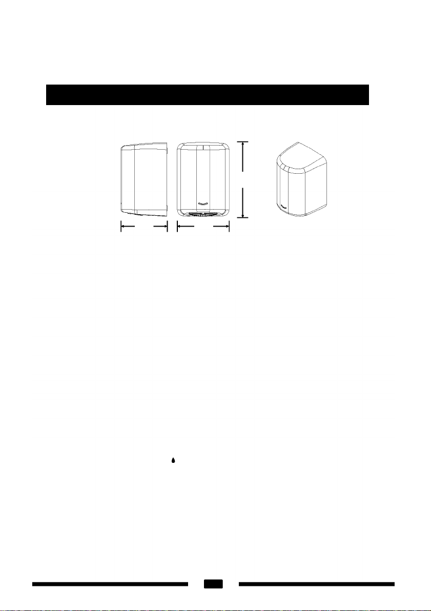
Surface-mounted high speed hand dryer
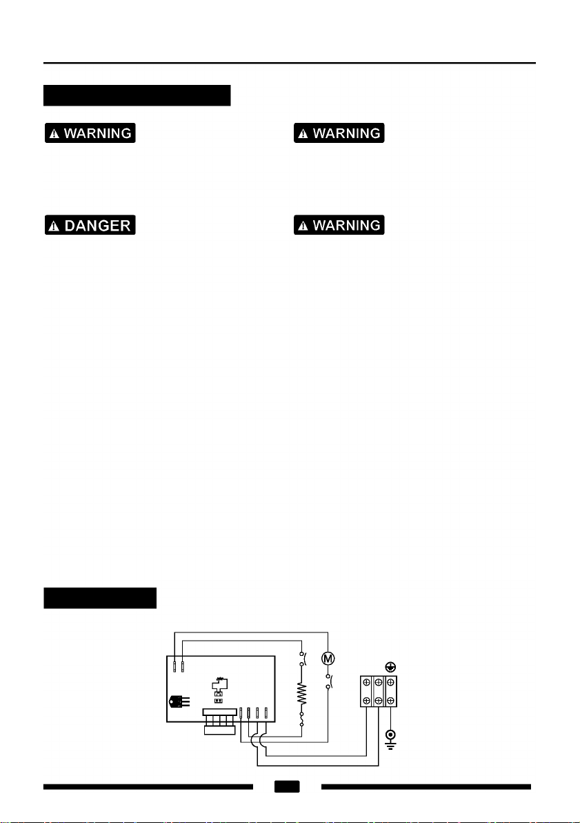
Diagnostics and Remedies
Symptom Corrective Actions for Initial Installation Failures
If the dryer will not run
The dryer cycles by itself
or runs constantly
The dryer makes a loud
Noise and does not run
for a complete cycle
The dryer runs but air
stream is low pressure
and/or low velocity
First ensure that the breaker supplying the dryer is operational. If it is,
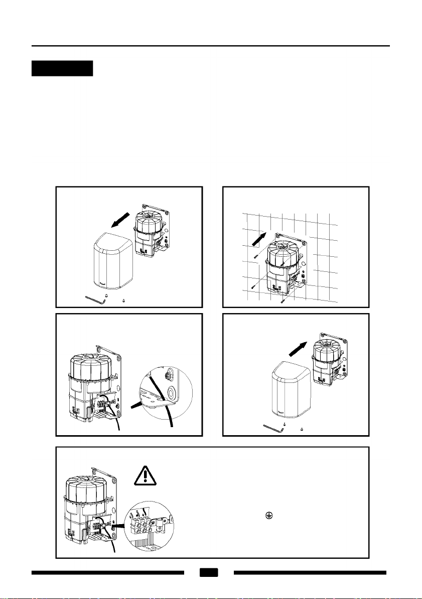
disconnect the power and remove the dryer cover. Taking suitable
precautions to avoid shock hazard, reconnect the power and check for
Voltage at the terminal block. Verify that connections are made correctly.
Adjust the VR to make sure it is not set too low.
Ensure that there is no obstruction on or in front of the IR sensor. Clean
any dirt or debris off the sensor lens. If problem persists, replace sensor.
Ensure that the supply Voltage is correct. Dryer will make a loud humming
noise if the input Voltage is too high. Verify Voltage requirement on unit
rating label and correct supply as required. If CBM has been damaged,
replace CBM, IR sensor module and VR component and cable.
Ensure that the supply Voltage is correct. Dryer will run weakly if the
input Voltage is too low. Verify Voltage requirement on unit rating label
and correct supply as required.
Symptom Corrective Actions for In-Service Failures
If the dryer will not run
The IR sensor only "sees"
close range objects
The heater gets hot but
no air stream is produced
The dryer only blows cold
air during a full cycle
The air stream is low
pressure and velocity
First ensure that the breaker supplying the dryer is operational. If it is,
disconnect the power and remove the dryer cover. Replace the CBM
and IR sensor module. Test the VR for open circuit (see Technical
Specifications for value). Replace VR if Ω= ∞. Taking suitable precautions
to avoid shock hazard, reconnect the power and check for Voltage at
the terminal block.
Ensure that there is no obstruction on or in front of the IR sensor. Clean
any dirt or debris off the sensor lens. If problem persists, disconnect the
power and remove the dryer cover. Taking suitable precautions to avoid
shock hazard, reconnect the power and try carefully adjusting the sensitivity
control (yellow shaft in blue box on CBM) to increase the sensing range.
If problem persists, replace sensor.
Disconnect the power. Remove the dryer cover and disassemble the blower-
motor/fan housing. Replace the fan motor.
Disconnect the power. Remove the dryer cover and disassemble the blower-
motor/fan housing. Test the thermostat for open circuit. Check the heater
element for signs of burning or breakage. Damaged element must be replaced.
Check the output nozzle for obstructions. If none are present, disconnect
the power. Remove the dryer cover. Remove any dust/lint buildup
from intake vent slots. Disassemble the blower-motor/fan housing.
Check the motor brushes for worn condition (
≤
25/64" [10 mm] graphite
remains) and replace them, if necessary.
5