Palstar AA30 User manual

Palstar Incorporated
9676 N. Looney Rd.,
Piqua, OH 45356 USA
Customer Service and Sales Telephone:
1-800-773-7931
Fax:
1-937-773-8003
Email:
in o@palstar.com
REV 2.1 03.18.2009
© Copyright 2010 Palstar Inc.
Printed in the U.S.A.
Owner’s Manual
AA30 Active
Antenna

1-8 00-773-7931 WWW.PALSTAR.COM
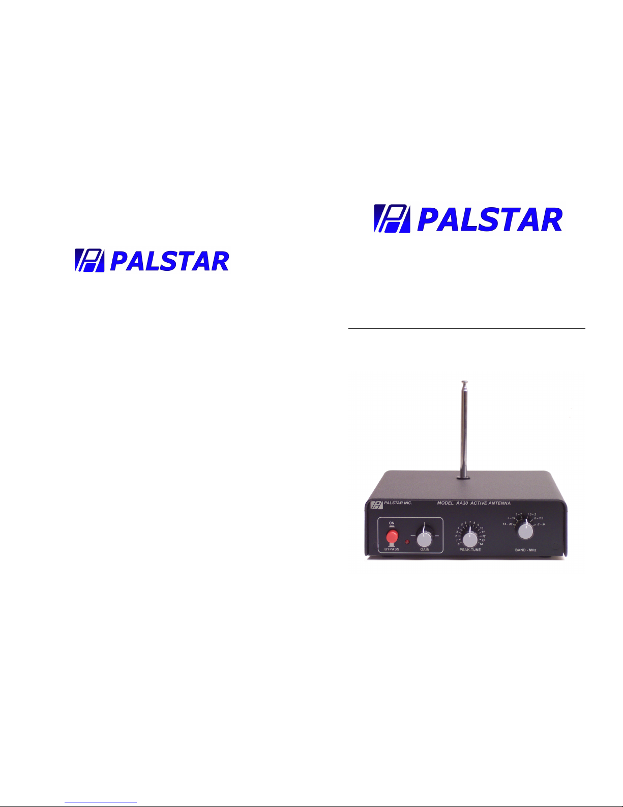
2 AA30 Active Antenna
Specifications:
Frequency Range 300 KHz to 30 MHz
Gain -10 to +15 db adjustable
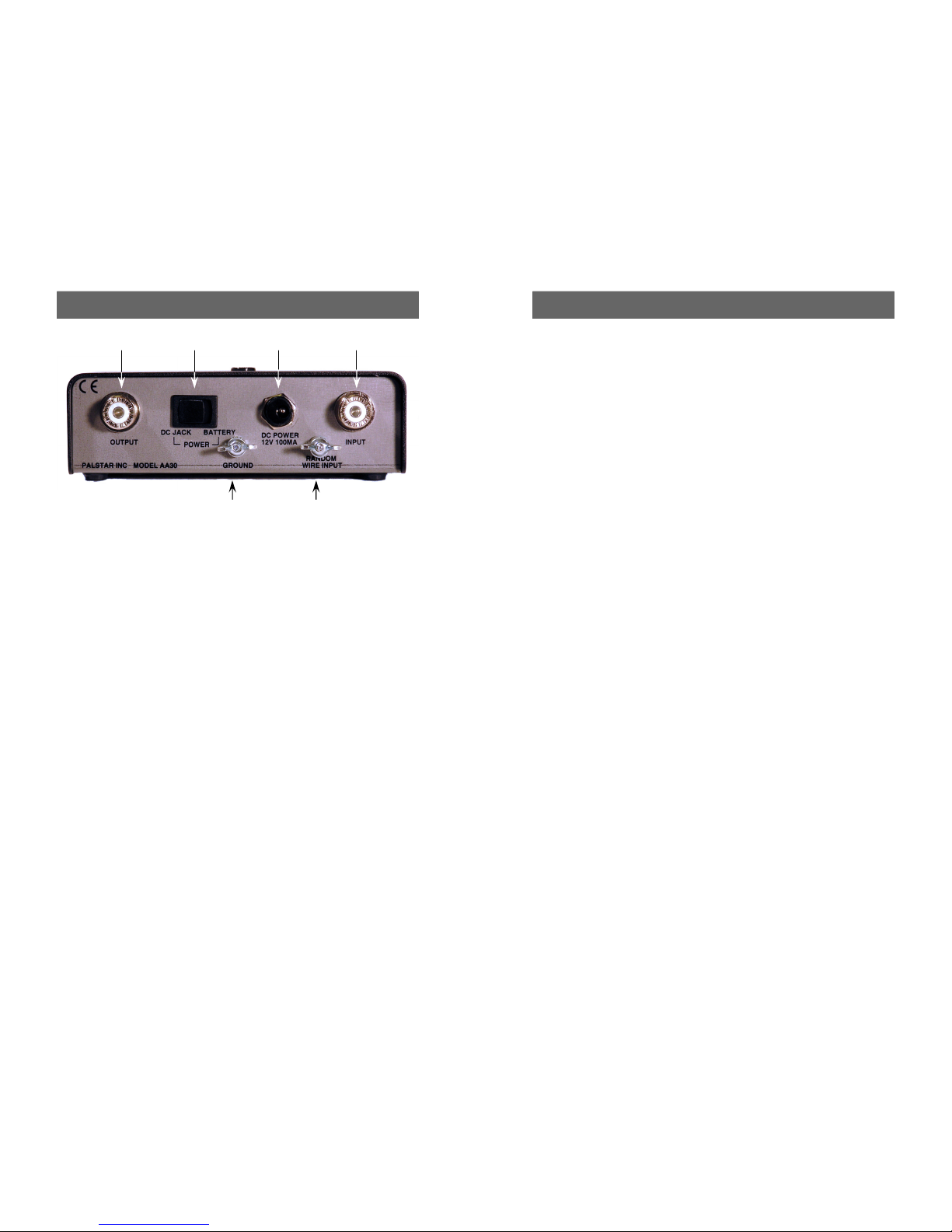
Antenna 50Ω SO-239, random wire or
20” telescoping whip
Power 9VDC PP3 battery or 12VDC
(2.1mm plug, center +). Rear
panel switch selects between
battery and AC adapter
Dimensions 1.75” H x 6” W x 6” D
Weight .5 Lbs
Description:
The AA30 Active Antenna is designed or the avid SWL
who is unable to put up an outdoor antenna.
Utilizing the built in whip antenna or an external wire, the
AA30’s pre-ampli ier circuit provides rom –10 to +15 db o
gain over a requency range o 300KHz to 30MHz.
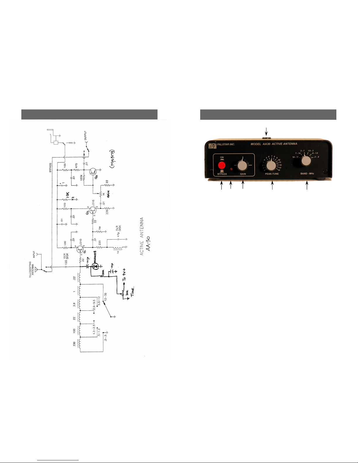
A varactor-tuned pre-selector with 6 band ranges prevents
strong out-o -band signals rom overloading the pre-
ampli ier.
Service and Warranty 7
1-8 00-773-7931 WWW.PALSTAR.COM
Limited Warranty
Palstar Inc. warrants products manu-
actured by it to be ree rom de ects
in material and workmanship under
normal use and service for a period
of one 1) year from the date of
delivery to the first buyer (the
“Warranty Period”). Palstar Inc’s obli-
gation under this warranty is limited to
repair or replacement o the product;
at its option at the Palstar actory in
Piqua, OH.
E ective only when the product is
returned to the actory with all trans-
portation charges prepaid and exami-
nation o the product discloses in Pal-
star’s judgment, to have been de ective
during the Warranty Period.
The Warranty Period shall not extend
beyond its original term with respect
to interim in-warranty repairs by Pal-
star. This Warranty Period shall not
apply to any product which has been
repaired or altered by anyone other
than Palstar without prior written
authorization. Warranty does not ex-
tend to any products which have been
subject to damage rom improper in-
stallation, application or maintenance in
accordance with the operating speci i-
cation. Palstar neither assumes nor
authorizes any person to assume or it
any obligation or liability other than
herein stated.
Repair Policy
When sending in a product or service,
please “double” box it care ully and
ship it insured or your protection.
Please include a note clearly describing
the problem, how you wish the item
returned and how you wish to pay or
the service. Package your radio prop-
erly. Palstar, Inc. is not responsible or
merchandise damaged in shipment.
Our service rate is $30 per hour (1/2
hr. minimum).
Return Policy
All returns must receive prior authori-
zation rom Palstar. Returned items
must be received in original—AS
SHIPPED– condition including the
original box, manuals, accessories, and
copy o sales receipt. Returns must be
within 14 days o purchase. Returned
items are subject to a 25% restocking
ee. Shipping is not re undable.

6 AA30 Schematic
LM7410
Power
Jack
9V
Battery
Power Select
Switch
1-8 00-773-7931 WWW.PALSTAR.COM
Front Panel 3
1
2 3 4 5
1. Telescoping Whip Socket. Insert Telescoping Whip
into this hole and screw it down until it is snug. Be care-
ul when starting so not as to cross-thread the ittings.
(Do not mount telescoping whip i you are using an ex-
ternal wire antenna.
2. On/Bypass Switch. Pressing the latching button to
the IN position turns on the pre-ampli ier and varactor
tuned pre-selector. When the button is in the OUT po-
sition, active circuits are turned o and antenna (wire or
telescoping) is bypassed directly to the output jack.
3. Indicator LED. Lights when On/Bypass Switch is ON.
4. Gain Control. Adjusts gain o pre-ampli ier.
5. Peak Tune. Tunes the varactor controlled pre-
selector.
6. Band Switch. Selects the requency tuning range o
the pre-selector.
6

4 Rear Panel
1-8 00-773-7931 WWW.PALSTAR.COM
1 2 3 4
5 6
1. Output SO-239 Jack. Connect to the Antenna Jack o
your receiver.
2. Power Select Switch. Select between external
power jack and internal 9v Battery (PP3).
3. DC Power Jack. 12VDC input or external power.
4. Input SO-239 Jack. For connecting a low impedance,
coax- ed antenna. Disconnect all antennas during light-
ning storms.
5. Ground Post. Connect a ground or counterpoise wire
to this post when using a single ended (non-dipole) an-
tenna. Disconnect during lightning storms.
6. Random Wire Antenna Post. For connecting a ran-
dom length wire antenna. Disconnect all antennas dur-
ing lightning storms.
Operation 5
1-8 00-773-7931 WWW.PALSTAR.COM
Operation:
1. I operating rom battery, remove the cover and install a 9V
battery (PP3), securing it in the battery clip on the circuit
board.
2. Chose the antenna you will use. I using the telescoping whip,
install as described on page 3. I using a wire antenna, con-
nect it to the appropriate connector (number 4 or 6 on page
4). Connect a ground wire (number 5, page 4) i needed. Do
not operate with both an external antenna and the telescop-
ing whip at the same time.
3. Select the power source with the switch on the back.
4. Connect the AA30 output to the antenna jack o your re-
ceiver.
5. Select the requency range you wish to use with the Band
Switch (number 6, page 3), and set the Gain Control (number
4, page 3) to 9 o’clock. Turn on receiver and AA30. The
LED on the ront panel will light.
6. Adjust the Tune control until an increase in signal is heard or
indicated on the receiver S-meter.
7. Most tuning will be between 5 and 14 on the Tune dial.
8. Increasing the Gain control beyond 12 o’clock is usually un-
necessary, and risks overloading the receiver or the AA30.
(The risk is bigger the longer your antenna is.)
9. You will notice that the tuning sharpness increases on the
low bands, and will be more broad on the higher bands.
10. Looking or the peaks where the AA30 tunes depends where
the Gain control is set, the conditions o the bands, and time
o day or night.
11. The bands tend to overlap at the band edges. I having trouble
tuning near a band edge, try switching to the next adjacent
higher or lower band.
12. Best results will be obtained with long wire antennas, even i
it is just wire strung around inside a room. However, good
results have been had with the short telescoping whip an-
tenna in the Medium Wave band.
13. A good ground is mandatory with long wires and generally is
a good practice. Disconnect ground and all antennas during
storms.
Table of contents
Popular Antenna manuals by other brands

IFM
IFM DTA Series quick start guide

Hy-Gain
Hy-Gain TH-3JRS instruction manual

EnGenius
EnGenius SN-900 installation instructions

Siklu
Siklu EtherHaul 8000 Series Installation, operation and maintenance manual

A.H. Systems
A.H. Systems SAS-551 Operation manual

A.H. Systems
A.H. Systems AK-4G Operation manual