Panasonic 140 Manual

Panasonic. IMM_ECOI-W_140-210_EN_09.19
September 2019
Read through the Installation Instructions before you proceed with the installation. In particular, you will need to read under
the “ IMPORTANT ! ” section at the top of the page.
INSTALLATION AND
MAINTENANCE MANUAL
“Original Language”
Heat Pump Chiller
This Heat Pump Chiller uses the refrigerant R410A.
Model No.
Outdoor Unit
Class Standard without
buffer tank With buffer tank
140 U-140CWNB U-140CWBL
150 U-150CWNB U-150CWBL
170 U-170CWNB U-170CWBL
190 U-190CWNB U-190CWBL
210 U-210CWNB U-210CWBL

2
Contents
PagePage
1. General recommendations . . . . . . . . . . . . . . . . . . . . . 5
1.1. Safety directions. . . . . . . . . . . . . . . . . . . . . . . . . 5
1.2. Warning . . . . . . . . . . . . . . . . . . . . . . . . . . . . . . . 5
1.3 Pressure equipment safety. . . . . . . . . . . . . . . . . 5
1.4. Equipment safety data . . . . . . . . . . . . . . . . . . . . 6
2. Inspection and storage . . . . . . . . . . . . . . . . . . . . . . . . 6
2.1 Disposal information. . . . . . . . . . . . . . . . . . . . . . 7
3. Warranty . . . . . . . . . . . . . . . . . . . . . . . . . . . . . . . . . . . . 7
4. Presentation . . . . . . . . . . . . . . . . . . . . . . . . . . . . . . . . . 7
5. Contents of package . . . . . . . . . . . . . . . . . . . . . . . . . . 8
5.1. Optional accessories . . . . . . . . . . . . . . . . . . . . . 8
6. Dimensions . . . . . . . . . . . . . . . . . . . . . . . . . . . . . . . . . 8
7. Handling . . . . . . . . . . . . . . . . . . . . . . . . . . . . . . . . . . . . 8
7.1. Net weight. . . . . . . . . . . . . . . . . . . . . . . . . . . . . . 8
7.2. Gravity center position . . . . . . . . . . . . . . . . . . . . 8
7.3. Handling generalities . . . . . . . . . . . . . . . . . . . . . 9
8. Technical specifications . . . . . . . . . . . . . . . . . . . . . . 11
8.1. Physical characteristics . . . . . . . . . . . . . . . . . . 11
8.2. Refrigeration specifications . . . . . . . . . . . . . . . 12
8.3. Electric specifications . . . . . . . . . . . . . . . . . . . . 13
8.4. Operating limits. . . . . . . . . . . . . . . . . . . . . . . . . 13
9. Installation . . . . . . . . . . . . . . . . . . . . . . . . . . . . . . . . . 14
9.1. Siting the installation. . . . . . . . . . . . . . . . . . . . . 14
9.2. Clearance . . . . . . . . . . . . . . . . . . . . . . . . . . . . . 15
9.3. Attachment to the ground . . . . . . . . . . . . . . . . . 15
10. Hydraulic links . . . . . . . . . . . . . . . . . . . . . . . . . . . . . . 16
10.1. Main hydraulic circuit . . . . . . . . . . . . . . . . . . . . 16
10.2. Anti-clogging protection . . . . . . . . . . . . . . . . . . 16
10.3. Minimum water volume requirements. . . . . . . . 17
10.4. Maximum water volume requirements . . . . . . . 17
10.5. Rinsing the circuit . . . . . . . . . . . . . . . . . . . . . . . 17
10.6. Frost protection. . . . . . . . . . . . . . . . . . . . . . . . . 18
10.7. Water quality. . . . . . . . . . . . . . . . . . . . . . . . . . . 19
10.8. Heat insulation . . . . . . . . . . . . . . . . . . . . . . . . . 20
10.9. Filling the system with water. . . . . . . . . . . . . . . 20
11. Wiring diagram and legend. . . . . . . . . . . . . . . . . . . . 21
11.1. Wiring diagram . . . . . . . . . . . . . . . . . . . . . . . . . 21
11.2. Legend . . . . . . . . . . . . . . . . . . . . . . . . . . . . . . . 21
12. Electrical connections. . . . . . . . . . . . . . . . . . . . . . . . 23
13. Control . . . . . . . . . . . . . . . . . . . . . . . . . . . . . . . . . . . . 25
13.1. Order of priority for control systems . . . . . . . . . 25
13.2. User interface . . . . . . . . . . . . . . . . . . . . . . . . . . 25
13.3. Initial settings . . . . . . . . . . . . . . . . . . . . . . . . . . 27
13.4. Launching the ECOi-W system . . . . . . . . . . . . 28
13.5. Alarms . . . . . . . . . . . . . . . . . . . . . . . . . . . . . . . 36
13.6. Schedule. . . . . . . . . . . . . . . . . . . . . . . . . . . . . . 37
14. Commissioning . . . . . . . . . . . . . . . . . . . . . . . . . . . . . 38
14.1. Pre-start check list . . . . . . . . . . . . . . . . . . . . . . 38
14.2. Operating check list . . . . . . . . . . . . . . . . . . . . . 39
15. In case of warranty - material return procedure . . . 40
16. Ordering service and spare parts order . . . . . . . . . 40
17. Maintenance . . . . . . . . . . . . . . . . . . . . . . . . . . . . . . . . 41
17.1. Weekly check . . . . . . . . . . . . . . . . . . . . . . . . . . 41
17.2. Periodic table of service and maintenance. . . . 42
17.3. Maintenance procedures . . . . . . . . . . . . . . . . . 44
18. Trouble shooting . . . . . . . . . . . . . . . . . . . . . . . . . . . . 46

3
IMPORTANT!
Please Read Before Starting
This air conditioner must be installed by the
sales dealer or installer.
This information is provided for use only by
authorized persons.
For safe installation and trouble-free
operation, you must:
• Carefully read this instruction booklet before
beginning.
• Follow each installation or repair step exactly
as shown.
• This air conditioner shall be installed in
accordance with National Wiring Regulations.
• This equipment complies with EMC directive
2014/30/EU.
• Pay close attention to all warning and caution
notices given in this manual.
WARNING
This symbol refers to a
hazard or unsafe practice
which can result in severe
personal injury or death.
CAUTION
This symbol refers to a hazard
or unsafe practice which can
result in personal injury or
product or property damage.
If Necessary, Get Help
These instructions are all you need for most
installation sites and maintenance conditions. If
you require help for a special problem, contact
our sales/service outlet or your certified dealer
for additional instructions.
In Case of Improper Installation
The manufacturer shall in no way be
responsible for improper installation or
maintenance service, including failure to follow
the instructions in this document.
Notice
The English text is the ‘Original language’
The content of this document is intended for
use by the manufacturer professional personnel
only.
SPECIAL PRECAUTIONS
WARNING When Wiring
ELECTRICAL SHOCK CAN
CAUSE SEVERE PERSONAL
INJURY OR DEATH. ONLY A
QUALIFIED, EXPERIENCED
ELECTRICIAN SHOULD
ATTEMPT TO WIRE THIS
SYSTEM.
• Do not supply power to the unit until all wiring
and tubing are completed or reconnected and
checked.
• Highly dangerous electrical voltages are
used in this system. Carefully see the wiring
diagram and section 2 when wiring. Improper
connections and inadequate grounding can
cause accidental injury or death.
• Connect all wiring tightly. Loose wiring may
cause overheating at connection points and a
possible fire hazard.
• Provide a power outlet to be used exclusively
for each unit.
• ELCB must be incorporated in the fixed
wiring. Circuit breaker must be incorporated
in the fixed wiring in accordance with the
wiring regulations.
Circuit
breaker
Circuit
breaker
U-140CW... 125A U-190CW... 160A
U-150CW... 125A U-210CW... 200A
U-170CW... 160A
* See Electrical Specifications Fuse rating aM, for systems
with alternate pump and fan options.
• Provide a power outlet exclusively for each
unit, and full disconnection means having
a contact separation by 3mm in all poles
must be incorporated in the fixed wiring in
accordance with the wiring rules.
• To prevent possible hazards from
insulation failure, the unit must be
grounded.
• This equipment is strongly recommended
to be installed with Earth Leakage Circuit
Breaker (ELCB) or Residual Current Device
(RCD). Otherwise, it may cause electrical
shock and fire in case of equipment
breakdown or insulation breakdown.

4
When Transporting
• It may need two or more people to
carry out the installation work.
• Care should be taken when lifting or
moving the liquid cooler to reduce
the chance of serious injury. Do not
attempt to move the equipment
without the correct means of lifting.
When Installing…
Select an installation location which is
rigid and strong enough to support or
hold the unit, and select a location for
easy maintenance.
…In Moist or Uneven Locations
Use a raised concrete pad or concrete
blocks to provide a solid, level
foundation for the outdoor unit. This
prevents water damage and abnormal
vibration.
…In an Area with High Winds
Securely anchor the outdoor unit down
with bolts and a metal frame. Provide a
suitable air baffle.
…In a Snowy Area (for Heat Pump-type
Systems)
Install the outdoor unit on a raised
platform that is higher than drifting
snow. Provide snow protection.
When Servicing
• Turn the power OFF at the main
power box (mains), wait at least
10 minutes until it is discharged,
then open the unit to check or repair
electrical parts and wiring.
• Keep your fingers and clothing away
from any moving parts.
• Clean up the site after you finish,
remembering to check that no metal
scraps or bits of wiring have been left
inside the unit.
WARNING
• This product must not be
modified or disassembled under
any circumstances. Modified or
disassembled unit may cause fire,
electric shock or injury.
• Users must not clean in side the
unit. Engage authorized dealer or
specialist for cleaning.
• In case of malfunction of this
appliance, do not repair by
yourself. Contact to the sales
dealer or service dealer for a repair
and disposal.
CAUTION
• Ventilate any enclosed areas when
installing or testing the refrigeration
system. Leaked refrigerant gas,
on contact with fire or heat, can
produce dangerously toxic gas.
• Confirm after installation that no
refrigerant gas is leaking. If the gas
comes in contact with a burning
stove, gas water heater, electric room
heater or other heat source, it can
cause the generation of toxic gas.
Others
When disposal of the product, comply
with national regulations.
CAUTION
• Do not touch the air inlet or
the sharp aluminum fins of
the outdoor unit. You may get
injured.
• Do not sit or step on the unit,
you may fall down accidentally.
• Do not stick any object into the
FAN CASE.
You may be injured and the unit
may be damaged.

5
POWER SUPPLY MUST BE SWITCHED OFF BEFORE STARTING WORK IN
THE ELECTRIC CONTROL BOX.
1. General recommendations
The purpose of this Manual is to provide users with instructions for installing, commissioning, using and maintaining the
units. It also contains instructions on starting up the machine as well as recommendations to avoid bodily injury and risks
of damage to the device during its operation.
It does not contain the complete description of all the maintenance operations guaranteeing the unit’s long life and
reliability. Only the services of a qualified technician can guarantee the unit’s safe operation over a long service life.
Please read the following safety precautions very carefully before installing the unit.
1.1. Safety directions
Follow the safety rules in forces when you are working on your appliance.
The installation, commissioning, use and maintenance of these units should be performed by qualified personnel having a
good knowledge of standards and local regulations, as well as experience of this type of equipment.
This appliance has not been designed for use by persons (including children) with reduced physical, sensorial or mental
faculties or by persons without any experience or knowledge of heating systems, unless they act under the safety and
supervision of a responsible person or have received prior training concerning the use of the appliance.
The unit should be handled using lifting and handling equipment appropriate to the unit’s size and weight.
Any wiring produced on site must comply with the corresponding national electrical regulations.
Make sure that the power supply and its frequency are adapted to the required electric current of operation, taking into
account specific conditions of the location and the current required for any other appliance connected to the same circuit.
The unit must be EARTHED to avoid any risks caused by insulation defects.
It is forbidden to start any work on the electrical components if water or high humidity is present on the installation site.
1.2. Warning
Cutoff power supply before starting to work on the appliance.
When making the hydraulic connections, ensure that no impurities are introduced into the pipe work.
The manufacturer declines any responsibility and the warranty becomes void if these instructions are not
respected.
If you meet a problem, please call the Technical Department of your area.
If possible, assemble the compulsory or optional accessories before placing the appliance on its final location (see
instructions provided with each accessory).
In order to become fully familiar with the appliance, we suggest to read also our Technical Instructions.
The information contained in these Instructions are subject to modification without advance notice.
1.3. Pressure equipment safety
Gas Fluid Group PS (bar) Category (1) Evaluation module (2) Notified body
R410A 2 42 2 D1 0062
1) According the 14 § 6 b) article of the directive 2014/68/EU.
2) According the 14 § 2 article of the directive 2014/68/EU.
• These units contain pressurised refrigerant. The pressurised elements within these units should only be disturbed during
maintenance by fully qualified and trained personnel.
• Do not damage, bend, or impact the pressurised pipe work.
• Failure to follow these recommendations may result in serious or fatal injury.

6
1.4. Equipment safety data
Safety Data R410A
Toxicity Low
In contact with skin
Skin contact with the rapidly evaporating liquid may cause tissue chilblains. In case of skin contact with the
liquid, warm the frozen tissue with water and call a doctor. Remove contaminated clothing and footwear. Wash
the clothing prior to re-use.
In contact with eyes Vapours have no effect. Liquid splashes or sprays may cause freeze burns. In these cases rinse your eyes with
running water or with a solution for eye lavages for at least 10 minutes. Immediately contact a doctor.
Ingestion In this case, burns may result. Do not attempt to make the patient vomit. If the patient is conscious, rinse the
mouth with water. Call a doctor immediately.
Inhalation
In case of inhalation, move the patient to an area with fresh air and provide oxygen if necessary. Perform
artificial respiration if the patient has stopped breathing or lacks air. In case of cardiac arrest, perform external
cardiac massage. Call a doctor immediately.
Further Medical Advice
Exposure to high concentrations can be dangerous for individuals with cardiac problems, as the presence of
catecholamines such as adrenalin in the bloodstream may lead to increased arrhythmia and possible cardiac
arrest.
Occupational exposure limits R410A: Recommended limits: 1,000 ppm v/v 8 hours TWA.
Stability Stable product
Conditions to avoid Increased pressure due to high temperatures may cause the container to explode. Keep out of the sun and do
not expose to a temperature >50°C.
Hazardous reactions Possibility of dangerous reactions in case of fire due to the presence of F and/or CI radicals
General precautions
Avoid the inhalation of high concentrations of vapours. The concentration in the atmosphere shall be kept at
the minimum value and anyway below the occupational limits. Since vapours are heavier than air and they
tend to stagnate and to build up in closed areas, any opening for ventilation shall be made at the lowest level.
Breathing protection In case of doubt about the actual concentration, wear breathing apparatus. It should be self-contained and
approved by the bodies for safety protection.
Storage Preservation Refrigerant containers shall be stored in a cool place, away from fire risk, direct sunlight and all heat sources,
such as radiators. The maximum temperature shall never exceed 50°C in the storage place.
Protection clothes Wear boots, safety gloves and glasses or masks for facial protection.
Behaviour in case of leaks or
escapes
Never forget to wear protection clothes and breathing apparatus. Isolate the source of the leakage, provided
that this operation may be performed in safety conditions. Any small quantity of refrigerant which may have
escaped in its liquid state may evaporate provided that the room is well ventilated. In case of a large leakage,
ventilate the room immediately. Stop the leakage with sand, earth or any suitable absorbing material. Prevent
the liquid refrigerant from flowing into drains, sewers, foundations or absorbing wells since its vapours may
create an asphyxiating atmosphere.
Disposal
The best procedure involves recovery and recycle. If this is not possible, the refrigerant shall be given to a
plant which is well equipped to destroy and neutralise any acid and toxic by-product which may derive from
its disposal.
Combustibility features R410A: Non-inflammable at ambient temperatures and atmospheric pressures.
Containers If they are exposed to the fire, they shall be constantly cooled down by water sprays. Containers may explode
if they are overheated.
Behaviour in case of fire In case of fire wear protection clothes and self-contained breathing apparatus.
2. Inspection and storage
At the time of receiving the equipment carefully cross check all the elements against the shipping documents in order to ensure
that all the crates and boxes have been received. Inspect all the units for any visible or hidden damage.
In the event of shipping damage, write precise details of the damage on the shipper’s delivery note and send
immediately a registered letter to the shipper within 48 hours, clearly stating the damage caused. Forward a copy of
this letter to the manufacturer or his representative.
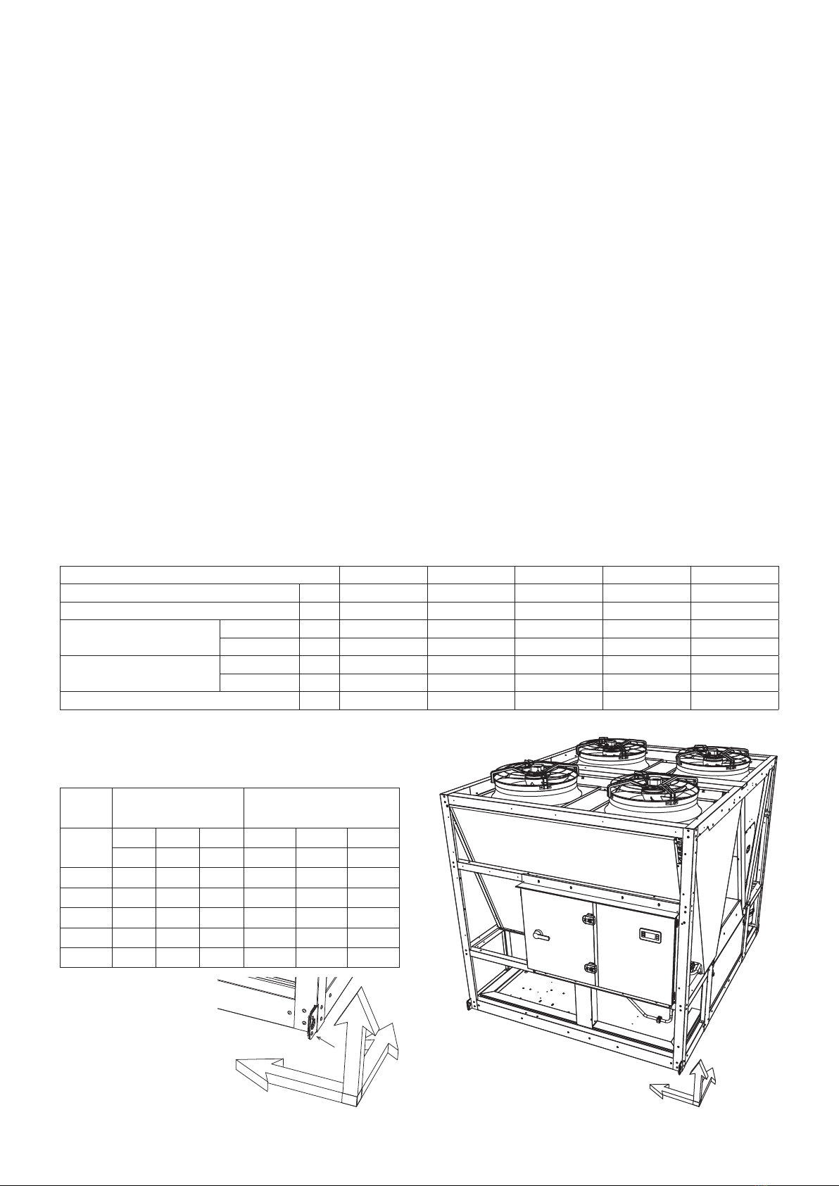
Never store or transport the unit upside down. It must be stored indoors, completely protected from rain, snow etc. The unit
must not be damaged by changes in the weather (high and low temperatures). Excessively high temperatures (above 60°C)
can harm certain plastic materials and cause permanent damage. Moreover, the performance of certain electrical or electronic
components can be impaired.

7
2.1. Disposal information
Units must be disposed of in accordance with local regulations
Information for Users on Collection and Disposal of Old Equipment and Used Batteries
These symbols on the products, packaging, and/or accompanying documents mean that used electrical and electronic products and
batteries should not be mixed with general household waste.
For proper treatment, recovery and recycling of old products and used batteries, please take them to applicable collection points, in
accordance with your national legislation and the Directives 2002/96/EC and 2006/66/EC.
By disposing of these products and batteries correctly, you will help to save valuable resources and prevent any potential negative
effects on human health and the environment which could otherwise arise from inappropriate waste handling.
For more information about collection and recycling of old products and batteries, please contact your local municipality, your waste
disposal service or the point of sale where you purchased the items.
Penalties may be applicable for incorrect disposal of this waste, in accordance with national legislation.
For business users in the European Union
If you wish to discard electrical and electronic equipment, please contact your dealer or supplier for further information.
[Information on Disposal in other Countries outside the European Union]
These symbols are only valid in the European Union. If you wish to discard these items, please contact your local authorities or dealer
and ask for the correct method of disposal.
Note for the battery symbol (bottom two symbol examples):
This symbol might be used in combination with a chemical symbol. In this case it complies with the requirement set by the Directive
for the chemical involved.
3. Warranty
The appliances are delivered fully assembled, factory tested and ready to operate.
Any modification to the units without the manufacturer’s prior approval, shall automatically render the warranty null and void.
The following conditions must be respected in order to maintain the validity of the warranty:
• Commissioning shall be performed by specialised technicians from technical services approved by the manufacturer.
• Maintenance shall be performed by technicians trained for this purpose.
• Only Original Equipment spare parts shall be used.
• All the operations listed in the present manual shall be performed within the required time limits.
THE WARRANTY SHALL BE NULL AND VOID IN THE EVENT OF NON-
COMPLIANCE WITH ANY OF THE ABOVE CONDITIONS.
4. Presentation
All the models in the ECOi-W liquid coolers range are produced to state-of-the-art design and manufacturing standards.
In this way, they offer guarantees of high performance and reliability as well as the capability of adapting to all types of air
conditioning installations operating with both chilled water and glycol solutions (and with hot water for the Heat pump units).
The unit, designed for an outdoor mounted application, is not suitable for any use other than those specified in the present
manual. Improper usage of the unit or a use for purposes other than those originally intended, without the prior approval by the
manufacturer or its agents, could result in the unit functioning outside its safe operating limits and could present risks to both
personnel and property.
ECOi-W are packaged units, optimized for air conditioning applications.
After the units are assembled, the refrigerating and electrical circuits are tested at the factory in order to guarantee correct
operation. The units are filled with an operational refrigerant fluid charge and are subjected to pressure tightness tests.
In cooling operation, the units can produce chilled water at temperatures varying between +18°C to +5°C or chilled water/
glycol solution at temperatures varying between +5°C to -10°C.
For heating operation, the units can produce hot water at temperatures varying between +20°C and +50°C.

8
5. Contents of package
1 ECOi-W
1 Water filter
1 Bag with the documentation
5.1. Optional accessories
Anti-vibration rubber pads
Spring pads
Isolating valve
Additional optional accessories are available. Please see Technical Data Manual for reference.
On opening the carton, check that all the accessories required for installation are present.
6. Dimensions
See appendix
7. Handling
7.1. Net weight
140 150 170 190 210
Cooling only - Without pump kg 1422 1425 1515 1584 1847
Heat pump - Without pump kg 1577 1597 1687 1777 2087
Standard pump 1 pump kg 90 90 90 93 93
2 pumps kg 122 122 122 131 131
High pressure pump 1 pump kg 106 106 106 106 106
2 pumps kg 150 150 150 150 150
Buffer tank Kg 132 132 132 132 132
7.2. Gravity center position
Without pump and
without buffer tank
With dual high pressure
pump and buffer tank
XGYGZGXGYGZG
mm mm mm mm mm mm
140 1241 1063 784 1 465 1 083 745
150 1241 1063 759 1 463 1 082 721
170 1255 1021 758 1 463 1 050 728
190 1253 1067 760 1 455 1 084 734
210 1265 1071 800 1 440 1 086 696
0
X
Y
Z

9
7.3. Handling generalities
The method of handling depends on the model of ECOi-W and its final destination.
• Take care to avoid any rough handling or impacts when unloading and moving the appliance.
• Before hoisting into position, test lift to insure stability and balance. Avoid twisting or uneven lifting of the units.
• The units shall be carefully inspected before unit installation to make sure that no handling damage has occurred.
• All these sections have been inspected before leaving the factory. It is therefore important to insure that no bolts, screws or
other fixing system are loosened or missing before the commissioning.
CAUTION Never submit the metal work (panels, posts) of the ECOi-W to handling constraints, as only its base is
designed for that purpose.
CAUTION Do not tilt the ECOi-W during handling, as it would be irrevocably damaged.
CAUTION Never move the ECOi-W on rollers.
CAUTION When handling the ECOi-W, beware not to damage the finned coil block. Protect it with cardboard or
particle panels.
7.3.1. Handling with a forklift
When a forklift is used to handle the 140/150/170/190/210 models, lift them only along their width.
Place a safety wedge between the unit base and the fork lift truck to avoid damaging the unit’s structure and casing.

10
7.3.2. Handling by slinging
Lifting is also possible by slinging.
A spreader must be used to prevent damage to the machine edges.
CAUTION Slings must never touch the unit casing of ECOi-W.
Without buffer tank
With buffer tank

11
8. Technical specifications
8.1. Physical characteristics
Models 140 150 170 190 210
Standard without buffer tank U-140CWNB U-150CWNB U-170CWNB U-190CWNB U-210CWNB
With buffer tank U-140CWBL U-150CWBL U-170CWBL U-190CWBL U-210CWBL
Power supply 400V / 3~ N / 50Hz
Cooling
Capacity kW 125,4 137,6 150,9 175,8 195,4
Power input kW 43,55 47,77 52,73 64,83 72,54
Total EER 100% *1 — 2,88 2,88 2,86 2,71 2,69
Energy class EER *2 —C C C C D
SEER *2 — 3,87 3,87 3,91 3,69 3,68
ηsc *2 — 152 152 153 145 144
Energy class SEER — C C C C D
Heating
Capacity kW 143,7 153,7 170,1 194,9 217,6
Power input kW 45,8 50,2 55,4 67,5 78,3
Total COP 100% *1 — 3,14 3,06 3,07 2,89 2,78
Energy class COP *2 —B B B C D
SCOP *2 — 3,32 3,36 3,31 3,29 3,23
ηsh *2 — 138 145 165 185 195
Energy class SCOP *2 —A+A+A+A+A+
Startup type Direct Direct Direct Direct Direct
Maximum operating current A 108 119 136 153 170
Startup current (without Soft Starter) A 251 262 324 341 396
Startup current (with Soft Starter) A 130 141 161 178 201
Refrigerant
Type R410A R410A R410A R410A R410A
Number of refrigerant circuit 2 2 2 2 2
Charge *3 kg 24,70 / 24,70 24,70 / 24,70 24,70 / 33,30 33,30 / 33,30 33,30 / 33,30
Compressors
Number 4 4 4 4 4
Type Scroll Scroll Scroll Scroll Scroll
Part load steps % 0/24/26/48/50
52/74/76/100
0/23/27/46/50
54/73/77/100
0/20/24/44/45
55/69/80/100
0/22/28/44/50
56/72/78/100
0/19/31/38/50
62/69/81/100
Crankcase heater W 66+66+66+66 66+66+66+66 66+66+82+66 82+66+82+66 95+66+95+66
Evaporator Number 1 1 1 1 1
Type Plate Plate Plate Plate Plate
Water flow Cooling m³/h 21,56 23,65 25,95 30,24 33,62
Heating m³/h 33 39 24 32 40
Water pressure drop Cooling kPa 24,73 26,45 29,58 33,52 37,44
Heating kPa 44 50 31 41 50
Water volume l 8,49 8,49 12,21 12,21 12,21
Antifreeze heater W 60 60 120 120 120
Coil
Number 4 4 4 4 4
Frontal surface m² 11,88 11,88 11,88 11,88 11,88
Number of rows 2 + 2 2 + 2 2 + 3 3 + 3 3 + 3
Fan
Number 4 4 4 4 4
Standard
Air flow m³/h 56000 56000 71000 86000 83000
Rotational speed tr/mn 900 900 900 900 900
Power input each fan W 940 940 940 - 1650 1650 1650
Water connections
Type Victaulic connection
Inlet diameter Inch 2"1/2 2"1/2 2"1/2 2"1/2 2"1/2
Outlet diameter Inch 2"1/2 2"1/2 2"1/2 2"1/2 2"1/2
Buffer tank (optional) Volume L 300 300 300 300 300
Dimensions without
buffer tank
Length mm 2856 2856 2856 2856 2856
Width mm 2210 2210 2210 2210 2210
Height mm 2295 2295 2321 2321 2321
Dimensions with buffer
tank
Length mm 3666 3666 3666 3666 3666
Width mm 2210 2210 2210 2210 2210
Height mm 2295 2295 2321 2321 2321
Weight Dry weight - Without
buffer tank kg 1577 1597 1687 1777 2087
Acoustical data Sound power level dB(A) 85,4 85,4 87,0 88,1 88,1
Sound pressure level * dB(A) 53,4 53,4 55,0 56,1 56,1
* Sound pressure levels calculated at 10 meters. Sound pressure levels refer to ISO standard 3744 with parallepiped shape.
*1 According to EN 14511-3:2011.
*2 According to Eurovent.
*3 Indicatives values - see nameplate.

12
8.2. Refrigeration specifications
8.2.1. Refrigerant circuit diagram
See appendix
8.2.2. Refrigerant charge
CAUTION This equipment contains fluorinated gas with greenhouse gas effects covered by the Kyoto agreement.
The type and quantity of refrigerating fluid per circuit are indicated on the product plate.
The installer and end user will get informed on local environmental regulations for the installation, operation and disposal of the
equipment ; more particularly, for the collection of substances hazardous for the environment (refrigerating fluid, oil, antifreeze,
etc.). A refrigerating fluid, whatever it is, must not be vented. Refrigerating fluids must be handled by skilled personnel.
CAUTION
ECOi-W units use the R410A fluoro-carbonated fluid, belonging to group 2 as defined in directive 2014/68/
UE. Considering the maximum operating pressure of these units (42 bar g), they integrate category 2 (or
lower) components as defined in directive 2014/68/UE.
8.2.3. Fluorocarbon gas regulations
The EC No. 517/2014 regulation covering fluorinated greenhouse gases requires of refrigeration equipment operators to
comply with the following five obligations:
1. Installation, servicing, maintenance as well as checking the sealing must be carried out by qualified personnel.
2. The fluorinated gas must be recovered during servicing and maintenance as well as the end of the installation.
3. All the necessary measures must be taken to prevent the leakage of fluorinated gases and any leaks must be repaired as
rapidly as possible.
4. Regular checks on any leaks must be performed according to the following conditions:
- for equipment containing fluorinated greenhouse gases in quantities greater than or equal to the equivalent of 5 tonnes
of CO2but less than the equivalent of 50 tonnes of CO2: at least every twelve months or, if a leak detection system is
installed, at least every twenty-four months
- for equipment containing fluorinated greenhouse gases in quantities greater than or equal to the equivalent of 50 tonnes of
CO2but less than the equivalent of 500 tonnes of CO2: at least every six months or, if a leak detection system is installed,
at least every twelve months
- for equipment containing fluorinated greenhouse gases in quantities greater than or equal to the equivalent of 500 tonnes
of CO2: at least every three months or, if a leak detection system is installed, at least every six months.
5. A document grouping a description of all the operations carried out on the cooling circuit must be drafted and conserved.
CAUTION
Non-compliance with one of these obligations constitutes an offense and can result in financial penalties.
Furthermore, compliance of the equipment with the fluorinated gases regulation must be proven to the
insurance company.
8.2.3.1. Calculating greenhouse gas quantities
Greenhouse gas quantity (kg of CO2) = Quantity of gas (kg) x gas’ GWP
Quantity of greenhouse gas expressed in weight (kg) and CO2 equivalent
Quantity of gas: amount of gas contained in the machine in kg (see ID plate)
GWP (Global Warming Potential) of the gas contained in the machine (see ID plate)
• GWP for the R410A = 2088

13
8.3. Electric specifications
140 150 170 190 210
Power supply 400V / 3~ N / 50Hz
Without
pump
Maximum current A 108 119 136 153 170
Fuse rating aM A 125 125 160 160 200
Total starting current (without Soft starter) A 251 262 324 341 396
Total starting current (with Soft starter) A 130 141 161 178 201
With
Standard
pump
Maximum current A 115 125 142 159 176
Fuse rating aM A 125 160 160 200 200
Total starting current (without Soft starter) A 257 268 331 347 403
Total starting current (with Soft starter) A 136 147 168 184 208
With High
pressure
pump
Maximum current A 119 130 146 163 180
Fuse rating aM A 125 160 160 200 200
Total starting current (without Soft starter) A 262 272 335 352 407
Total starting current (with Soft starter) A 141 151 172 189 212
IMPORTANT
* This data is given for guidance only. Values must be checked and verified at commissioning according to prevailing
standards. They depend on the installation and the cables used.
It is mandatory to supply a main fuse or suitable circuit breaking device on the power supply.
• Fuses not supplied
• Cables not supplied
8.4. Operating limits
8.4.1. Cooling mode
55
50
45
40
35
30
25
20
15
10
5
0
-5
-10
-15
25
20
15
10
5
0
-5
-10
-15
-20
-15 -10 -5 0 5 10 15 20
15 20 25 30 35 40 45 50 55 60
Air temperature (°C)Air temperature (°C)
Leaving water temperature (°C)
BRINES or WATER +
GLYCOL
BRINES or WATER +
GLYCOL +
Fan speed controller
WATER
WATER +
Fan speed controller
8.4.2. Heating mode*
* 55°C can be achieved with periodic operation.
Please contact your local Panasonic sales or
service representative for full details.

14
9. Installation
CAUTION
The unit is not designed to withstand weights or stresses from adjacent equipment, pipe work or
constructions. Any foreign weight or stress on the unit structure could lead to a malfunction or a
degradation with dangerous consequences for personnel and property. In such an event, the warranty shall
be null and void.
CAUTION The unit base shall be arranged as indicated in the manual. There could be a risk of personal injury or
damage to property in the event of the unit being incorrectly supported.
9.1. Siting the installation
The ECOi-W must be installed outdoors with sufficient surrounding clearance to enable unobstructed air circulation through
the appliance and access for maintenance work.
CAUTION Do not expose the ECOi-W to emissions from chimneys or vents. Fumes charged with soot or grease as
well as acidity are likely to clog or damage the condenser irrevocably. This would void the warranty.
Prevailing wind
In the case of the unit being sited in areas exposed to high winds, you must avoid the wind hitting the fan blowing surface
areas directly to avoid any risk of recycling cooled air. Exchanger fan operation can be disrupted by strong winds, which can
cause de-icing problems and fan malfunctions.
CAUTION Unit operation depends on air temperature. Any recycling of air extracted by the fan lowers the air intake
temperature across the exchanger fins and alters the standard operating conditions.
9.1.1. Condensate water management in heating mode
Depending on temperature and outdoor air humidity conditions, water vapour contained in the air can condense on the finned
heat exchanger and even form ice under low outdoor temperature conditions (around < 5°C). This condensate water and
defrosted water runs off via outlets provided under the exchanger. To aid water run-off and avoid frozen water remaining in the
appliance in winter, we recommend that it is mounted at a height ≥100mm above the ground or supporting structure. In this
way, water can run off freely and be absorbed into the ground, or channelled to a basin built under the appliance, in order to
protect the environment.
In areas where outdoor temperatures fall below 1°C, the system can be equipped with a condensate anti-freeze protection
system (e.g. a heated pipe sheath, optional accessory not supplied with the standard unit).
9.1.2. How to reduce noise pollution
In order to contain noise levels, we equip our appliances with quiet fans and encase the technical compartment in sound-
proofed panels. However, noise levels can be reduced even further by following a few installation precautions:
• Do not install the appliance near a window.
• Do not install the unit in enclosed or confined yards, narrow locations where noise may be reflected on walls.
• Install rubber pads or anti-vibration pads (available as an option) under the appliance.
• Do not join the concrete slab supporting the appliance to the structure of the dwelling (structure- borne noise transmission).
• Electrical and hydraulic connections to the unit must be flexible to avoid transmitting vibrations.

15
9.2. Clearance
When choosing the location for the ECOi-W, take care to
leave sufficient free clearance on all sides to ensure easy
access for maintenance work.
The minimum free clearance dimensions indicated must be
observed to ensure both proper system operation and allow
access for maintenance and cleaning.
CAUTION When several ECOi-W units are installed, ensure proper clearance is implemented around the condensers
specific to each machine.
9.3. Attachment to the ground
The surface of the floor or structure located under the ECOi-W must be flat, and with sufficient strength to withstand the unit’s
weight with its full liquid load, and occasional presence of maintenance equipment.
For normal applications, rigidity of the ECOi-W and the
positions of supports allow for an installation minimizing
vibrations. However, the installers can use anti-vibration
rubber pads (supplied optionally).
The ECOi-W does not require anchoring on the foundations,
except in regions exposed to a high earthquake risk or if the
device is installed on a high level on a steel frame.
When fitting anti-vibration pads, refer to the manual supplied with the kit.
Without buffer tank
With buffer tank
Without buffer tank
With buffer tank
5000
1500
2000
1500
1500
5000
1500
1500
1500
1500
2148
152 1145 1249
152 1145
1249
2148
152 1145 1249
152 1145
1249

16
10. Hydraulic links
CAUTION When choosing and installing water pipes, you must consult and observe all current local standards,
regulations and instructions.
10.1. Main hydraulic circuit
CAUTION The main hydraulic circuit will provide a constant water flow on the refrigerating fluid/water plate exchanger
in case of load variation.
You must design the pipe network with the minimum number of bends and keep the number of changes in height to the strict
minimum. This will help to reduce installation costs and ensure optimum system performance. The pipe network must include:
• A vibration elimination system (e.g.: link hoses available as an accessory) on all pipes connected to the appliance in order to
reduce vibrations and noise transmitted to the building fabric.
• A balancing valve on the water outlet pipe in order to adjust the water flow.
• Stop cocks to isolate the hydraulic circuit during maintenance.
• Manual or automatic bleed valves at the highest points on the water circuit.
• Drain points at all low points to allow complete circuit draining
• A circulation pump guaranteeing flow necessary for the operation of the ECOi-W unit. This may be a pump fitted within the
unit.
• A diaphragm expansion tank fitted with a safety pressure relief valve and draining valve must be visible.
• A low water pressure sensor (available as option), to secure the water pump against cavitation if the water pressure in the
circuit decreases.
• The installation of thermometers and pressure gauges on the heat exchanger inlet and outlet to facilitate day-to-day controls
and system maintenance.
• An element ensuring ground continuity of all piping. An unbalance of grounding connection points can cause electrolytic
corrosion.
CAUTION The expansion tank must be dimensioned to be able to absorb an expansion corresponding to 2% total
volume of water contained in the installation (exchanger, piping, installations and buffer tank, if present).
CAUTION The warranty does not cover damage due to corrosion resulting from electrolytic phenomena.
10.2. Anti-clogging protection
CAUTION To avoid any risk of foreign bodies entering the appliance and to guarantee operating performance, it is
imperative to install water filter on the ECOi-W inlet pipe.
Failure to install the filter to the inlet of the ECOi-W
could result in blockage within the plate heat
exchanger. Should there be insufficient water flow rate,
it may result in IRREVOCABLE damage.
A filter mesh ≤800µm is required.
CAUTION The manufacturer’s warranty is void
if the filter supplied with the ECOi-W is not installed to protect the appliance.

17
10.3. Minimum water volume requirements
To ensure that the system operates correctly you must use suitably sized and properly routed pipes for the hydraulic links
between the ECOi-W and the main network. Proper operation of the control and safety devices is ensured only when the water
volume is sufficient.
For cooling only operation, the total volume on the level of the primary water circuit must never below:
• application air conditioning
- 3,5 L/kW refrigeration power
• application process
- 10 L/kW refrigeration power
When utilising heating mode, a water volume equal to 6,5 L/kW is recommended, so that energy reserves are enough to ensure
the defrosting cycle without any discomfort for the end user.
If the total volume of the primary hydraulic circuit does not allow to reach these recommendations, a buffer tank or volumiser
must be added to the installation, to increase the water volume up to the minimum required value.
If the unit runs with a low volume of water (with air treatment plant…) or if it is used for industrial processes, a buffer tank or
volumiser is compulsory to guarantee sufficient thermal inertia and satisfactory temperature stability.
A buffer tank can be required to increase the water volume of the whole hydraulic circuit in the system, so as to reach the
minimum water volume requested.
Internal buffer tank:
• 140/150/170/190/210 models: 300L
10.3.1. Cooling only operation
140 150 170 190 210
Minimum water volume in the system application air conditioning L469 515 565 658 731
Minimum water volume in the system application process 1340 1470 1612 1878 2088
10.3.2. Heating operation
140 150 170 190 210
Minimum water volume in the system L935 1000 1106 1268 1415
10.4. Maximum water volume requirements
The maximum water volume is limited by the sizing of the unit’s expansion tank and/or the expansion tank present in the
facility’s hydraulic circuit. Expansion tanks must be sized according to the glycol percentage in the hydraulic circuit.
The expansion tank should be installed at the pump suction, and the pressure inside will be adjusted by taking into account
the whole hydraulic circuit.
The volume of the expansion tanks selected with Single pump and double pump options are:
140 150 170 190 210
Volume of the expansion tank supplied with hydraulic options L25 25 25 25 25
10.5. Rinsing the circuit
CAUTION Before filling the installation, check it and remove any contamination such as sand, stone, welding chips
and other materials likely to damage the ECOi-W.
Fully rinse all water pipes before final connection to the ECOi-W.
When using an off-the-shelf acid rinsing solution, implement a temporary branching around the ECOi-W to prevent damaging
internal components (particularly the plate exchanger, flow switch, pump...).

18
10.6. Frost protection
10.6.1. Water loop glycoling
CAUTION The use of a glycol-based solution is the only effective frost-protection means
The glycol-based water solution must be sufficiently concentrated to ensure appropriate protection and prevent ice from
forming. Take precautions when using non inert MEG antifreeze solutions (Mono Ethylene Glycol) or MPG (Mono Propylene
Glycol). With this type of antifreeze solution, corrosion may occur in the presence of oxygen.
Contact glycol resellers to ensure that its characteristics are compatible with environmental directives applicable on site (this is
not under manufacturer responsibility).
CAUTION
Glycol concentration in the installation’s hydraulic circuit must be entered in the controller upon start-up.
This parameter setting changes the safety and alarm triggering threshold limits. An incorrect value may
cause malfunctions and potential destruction of the unit’s heat exchanger.
AVERTISSEMENT It is strongly recommended to post, on the electric box of the unit, glycol type and concentration in
the hydraulic circuit.
Glycoling the water loop worsens slightly the performances, in particular the pressure drops. The hereunder table gives
corrective factors with respect of type and concentration of the glycol. For instance, the 20% MEG glycoling will:
• Increase the pressure drop: with glycol = 1,160 x without glycol
• Increase the flow rate: with glycol = 1,050 x without glycol
• Decrease the capacity: with glycol = 0,985 x without glycol
Mono Ethylene Glycol concentration % 10 20 30 45
Correction factor
Load loss 1,070 1,160 1,235 1,368
Water flow 1,015 1,050 1,085 1,169
Thermodynamic power 0,995 0,985 0,970 0,949
Mono Propylene Glycol concentration % 10 20 30 45
Correction factor
Load loss 1,112 1,175 1,290 1,520
Water flow 1,005 1,030 1,067 1,162
Thermodynamic power 0,991 0,977 0,945 0,894
Draining the water circuit is not recommended for frost protection, for the following reasons:
• The water circuit will rust, which will shorten its lifetime.
• Water will remain at the bottom of the plate exchangers and freezing may cause damage.
CAUTION
Never fill the hydraulic circuit with pure glycol. Maximum glycol concentration is 45%. The water and glycol
mixture must be precisely prepared before filling the hydraulic circuit. If the mixture is too concentrated, the
hydraulic circuit components may be damaged and the ECOi-W unit may not perform normally. In this case,
unit warranty will be void.
CAUTION For Heat pump models, if the outdoor temperature is likely to fall below +1°C, provide means to prevent the
condensates from freezing (e.g. heating cord).
10.6.2. Outer air protection
In case of negative temperatures, the water loop must be protected against icing when the unit is off. Concentration must
comply with the temperature level:
Minimum outer air temperature °C 5 > T > 0 0 > T > -5 -5 > T > -10 -10 > T > -27
MEG concentration % 10 20 30 45
MPG concentration % 10 20 30 45

19
10.6.3. Leaving water protection
In case of low temperature setpoint or reduced water flow, the water loop must be protected against icing during the operation
of the unit. Concentration must comply with the minimum water temperature of the installation. The choice of the type of glycol
shall take in consideration the increase of pressure drops.
For instance, we recommend to protect a -10°C setpoint down to -18°C. Using MPG, that protection is achieved with a 35%
concentration.
10.7. Water quality
The water must be analyzed; the hydraulic network system installed must include all elements necessary for water treatment:
filters, additives, intermediate exchangers, drain valves, vents, check valves, etc., according to the results of the analysis.
CAUTION The ECOi-W must not run on a network with open loops, this is likely to cause incidents related to
oxygenation, or with non treated table water.
Using improperly treated or non treated water in the ECOi-W may cause scaling, erosion, corrosion, algae or sludge deposits in
the exchangers. Refer to a specialist skilled in water treatment to determine any treatment to apply. The manufacturer will not
be held liable for damages caused when non-treated or improperly treated water, demineralized water, salty water or sea water
are used.
Apply the following guidelines:
• No NH4
+ammonium ions in the water, highly detrimental to copper. <10mg/l
• Cl- chloride ions are detrimental to copper with a risk of puncture by pitting corrosion. <10mg/l.
• SO4
2- sulphate ions may cause perforating corrosion. < 30mg/l.
• No fluoride ions (<0,1 mg/l)
• No Fe2+ and Fe3+ ions, particularly in case of dissolved oxygen. Fe< 5mg/l with dissolved oxygen < 5mg/l. The presence of
these ions with dissolved oxygen indicates corrosion of steel parts, likely to generate corrosion of copper parts under Fe
deposits, particularly in the case of multitubular exchangers.
• Dissolved silica: silica is an acid element of water and may also cause corrosion. Content < 1mg/l.
• Water hardness: Values between 10°fH and 25°fH may be recommended. This facilitates scaling deposits likely to limit
copper corrosion. Excess TH values may lead to clogging the pipes.
• TAC<100
• Dissolved oxygen: Prevent any sudden change in the water’s oxygenation conditions. Also, avoid deoxygenating water by
sparging inert gas as well as overoxygenating it by pure oxygen sparging. Disturbing oxygenation conditions destabilizes
copper hydroxides and particle salting-out.
• Electrical Resistivity - Conductivity: The higher the resistivity, the slower the corrosion. Values above 3000 ohm/cm are
preferred. A neutral environment favours maximum resistivity. For electrical conductivity, values around 200-600 S/cm can be
recommended.
• pH: neutral pH at 20°C (7 < pH < 8)
CAUTION If the water circuit is to be drained for a time exceeding one month, the circuit must be fully charged with
nitrogen to prevent any risk of corrosion by differential venting.
CAUTION
The manufacturer is not liable for recommendations in terms of water treatment (call a specialized
company). However, this matter has a critical nature, and particular care must be given to ensure that the
type of treatment applied is effective. The liability of the manufacturer or its representative will not be sought
when non-treated water or non-compliant quality water is used.

20
10.8. Heat insulation
To guarantee proper energy efficiency and compliance with current standards, water pipes passing through uninhabited zones
should be properly lagged to retain heat.
To achieve correct insulation with resistivity of 0,04 W/mK, lag the pipes with insulating material with a radial thickness
between 25mm and 30 mm.
10.9. Filling the system with water
CAUTION Filling or draining the water circuit must be performed by skilled persons using the appropriate devices on
the external hydraulic circuit by the installer.
It is important to ensure that the mains water supply pressure is sufficient to fill the installation.
Once the installation is complete and after having clean and rinsed out the circuit network, you must fill the water circuit in
accordance with current professional standards until you obtain the service pressure which will be:
0,5 bar < Service Pressure < 2,5 bar
A 3,5 bar safety valve is mounted in the unit when hydraulic options are selected (single or double pump).
Always check that the manual or automatic air purge valves are installed at all the high points of the hydraulic network.
When two or three units are connected in parallel, it is recommended that the return circuit connections are reversed
(Tichelmann loop system) in order to reduce the pressure loss in each unit’s circuit.
Install a balancing valve on the output pipe to adjust the water flow.
CAUTION The water inlets and outlets must be connected as described on the labels affixed near the connections.
When the hydraulic pump option is selected, a safety valve
is mounted (factory assembled) at the Aqualogic water inlet
to prevent over pressurising the circuit. The installer must
install a drain pipe at the safety valve to allow for removal of
water.
VV VR
VV VR
UNIT 1
UNIT 2
V: Isolating valves. VR: Balancing valves.
This manual suits for next models
14
Table of contents
Popular Chiller manuals by other brands

Carrier
Carrier AquaForce 30XQ0502 Installation, operation & maintenance instructions

S&A
S&A CW-5000 Series Service and repair handbook

Carrier
Carrier 17EX Series Start-up, operation and maintenance instructions

York
York YMC2 Installation and assembly

Skope
Skope SC112N-AC manual

Nordcap
Nordcap SKF 12 GN 1/1 Installation

Thermo
Thermo NESLAB RTE Series Installation, Operation, Basic Maintenance

York
York MILLENNIUM YCAL0043SC manual

Randell
Randell BC-18-PUB Operator's manual

Haier
Haier CA0070AANB Installation & operation manual

Galletti
Galletti MCA Series Technical manual

SMC Networks
SMC Networks HRS-R Series Operation manual