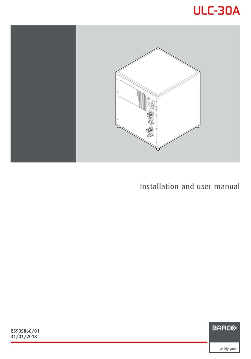
Barco ULC-30A User manual

ULC-30A
Service manual
R5906015/01
01/02/2018

Barco NV
President Kennedypark 35, 8500 Kortrijk, Belgium
Phone: +32 56.36.82.11
Fax: +32 56.36.883.86
Support: www.barco.com/en/support
Visit us at the web: www.barco.com
Printed in Belgium

Copyright ©
All rights reserved. No part of this document may be copied, reproduced or translated. It shall not otherwise be recorded, transmitted or
stored in a retrieval system without the prior written consent of Barco.
Trademarks
Brand and product names mentioned in this manual may be trademarks, registered trademarks or copyrights of their respective holders.
All brand and product names mentioned in this manual serve as comments or examples and are not to be understood as advertising for
the products or their manufacturers.
Changes
Barco provides this manual ’as is’ without warranty of any kind, either expressed or implied, including but not limited to the implied war-
ranties or merchantability and fitness for a particular purpose. Barco may make improvements and/or changes to the product(s) and/or the
program(s) described in this publication at any time without notice.
This publication could contain technical inaccuracies or typographical errors. Changes are periodically made to the information in this
publication; these changes are incorporated in new editions of this publication.
The latest edition of Barco manuals can be downloaded from the Barco web site www.barco.com or from the secured Barco web site
https://www.barco.com/en/signin.


Table of contents
TABLE OF CONTENTS
1. Safety................................................................................................................. 3
1.1 Servicing safety instructions ......................................................................................................... 3
2. General information................................................................................................ 7
2.1 Conventions .......................................................................................................................... 7
2.2 General description. .................................................................................................................. 7
2.3 Covers ................................................................................................................................ 8
2.4 Service kit............................................................................................................................. 9
2.5 Chiller service tool . . .................................................................................................................. 9
3. Preventive maintenance .........................................................................................13
3.1 Monthly maintenance................................................................................................................13
3.2 Yearly maintenance..................................................................................................................13
3.3 3 yearly maintenance................................................................................................................13
3.4 30000 hours maintenance. . ......................................................................................................... 13
4. Switching on/off power...........................................................................................15
4.1 Switching off power and locking the switch.........................................................................................15
4.2 Switching on power..................................................................................................................15
5. Covers...............................................................................................................17
5.1 Removing a cover ...................................................................................................................17
5.2 Installing a cover.....................................................................................................................18
6. Fan unit .............................................................................................................21
6.1 Removal of the fan unit..............................................................................................................21
6.2 Installation of the fan unit............................................................................................................ 22
7. Coolant procedures...............................................................................................25
7.1 First use of the Chiller service kit — Air removal procedure .. .....................................................................25
7.2 Draining the coolant circuit..........................................................................................................26
7.3 Filling the coolant circuit.............................................................................................................28
7.4 Adding coolant to the tank...........................................................................................................31
7.5 Replacing the tank cap assembly...................................................................................................33
7.6 Cooling liquid visual check ..........................................................................................................35
8. Primary pump unit ................................................................................................37
8.1 Primary pump replacement process ................................................................................................37
8.2 Disconnecting the primary pump wiring . .. . ........................................................................................38
8.3 Removing the primary pump unit . ..................................................................................................40
8.4 Installing the primary pump unit.. ...................................................................................................43
8.5 Connecting the primary pump wiring................................................................................................45
9. Secondary cooling unit...........................................................................................47
9.1 Removing the Secondary cooling unit .............................................................................................. 47
9.2 Installing the Secondary cooling unit ...............................................................................................51
10. Refrigeration unit..................................................................................................55
10.1 Refrigeration unit replacement process. . . . . ........................................................................................55
10.2 Removing the refrigeration unit .....................................................................................................56
10.3 Installing the refrigeration unit.......................................................................................................61
11. Electronics Unit....................................................................................................67
11.1 SD logging status . . . .................................................................................................................67
11.2 Removing the electronics unit.......................................................................................................67
11.3 Installing the electronics unit ........................................................................................................71
11.4 Replacing the logic board . . .........................................................................................................75
11.5 Pump inverter replacement .........................................................................................................77
11.5.1 Removing the J1000 pump inverter . . ........................................................................................77
11.5.2 Installing the J1000 pump inverter ... ........................................................................................79
11.5.3 Removing the V1000 pump inverter. . ........................................................................................ 82
11.5.4 Installing the V1000 pump inverter .. . ........................................................................................84
12. Pressurization Unit................................................................................................89
12.1 Removing the pressurization Unit...................................................................................................89
12.2 Installing the pressurization Unit .................................................................................................... 91
13. Air filter..............................................................................................................93
13.1 Replacing the filter...................................................................................................................93
13.2 Vacuum cleaning of the dust filters .................................................................................................94
A. Appendix .............................................................................................................95
A.1 Hazards..............................................................................................................................95
R5906015 ULC-30A 01/02/2018 1

1. Safety
1. SAFETY
About this chapter
Read this chapter attentively. It contains important information to prevent personal injury while servicing the ULC-30A on-site. Fur-
thermore, it includes several cautions to prevent damage of the ULC-30A components. Ensure you understand and follow all the
safety guidelines, safety instructions and warnings mentioned in this chapter before performing any servicing on the ULC-30A. After
this chapter additional “warnings” and “cautions” are given depending on the servicing procedure. Read and follow these “warnings”
and “cautions” as well.
WARNING:This manual is only intended for qualified service personnel.
Overview
• Servicing safety instructions
1.1 Servicing safety instructions
WARNING:Before removing/replacing any chiller components, switch off power. See "Switching off power
and locking the switch", page 15.
Personal protection
WARNING:Ensure you understand and follow all the safety guidelines, safety instructions, warnings and
cautions mentioned in this manual.
R5906015 ULC-30A 01/02/2018 3

1. Safety
Safety Instructions
1. Before returning the chiller to the customer, always make a safety check of the entire chiller, including, but not limited to, the
following items:
a) Be sure that no built-in protective devices are defective and/or have been defeated during servicing. (1) Protective shields
are provided on this chassis to protect both the technician and the customer. Correctly replace all missing protective shields,
including any removed for servicing convenience. (2) When reinstalling the chassis and/or other assembly in the cabinet,
be sure to put back in place all protective devices, including, but not limited to, insulating materials, barriers, covers/shields,
and isolation resistor/capacitor networks. Do not operate this chiller or permit it to be operated without all protective devices
correctly installed and functioning. Service people who defeat safety features or fail to perform safety checks may be liable
for any resulting damage.
b) Be sure that there are no cabinet openings through which an adult or child might be able to insert their fingers and contact a
hazardous voltage. Such openings include, but are not limited to, (1) excessively wide cabinet ventilation slots, and (2) an
improperly fitted and/or incorrectly secured cover panels.
c) Leakage Current Hot Check. With the chiller completely reassembled, plug the AC line cord directly into a 220 V AC outlet
(Do not use an isolation transformer during this test). Use a leakage current tester or a metering system that is designed
to comply with the new IEC, ANSI and UL standards. With the chiller AC switch first in the on position and then in the
off position, measure from a known earth ground (metal waterpipe, conduit, etc.) to all exposed metal parts of the chiller
(antennas, handle bracket, metal cabinet, screwheads, metallic overlays, control shafts, etc.). especially any exposed metal
parts that offer an electrical return path to the chassis. Any current measured must not exceed 3,5 mA. Reverse the chiller
power cord plug in the outlet and repeat test. ANY MEASUREMENTS NOT WITHIN THE LIMITS SPECIFIED HEREIN
INDICATE A POTENTIAL SHOCK HAZARD THAT MUST BE ELIMINATED BEFORE RETURNING THE INSTRUMENT
TO THE CUSTOMER OR BEFORE CONNECTING ACCESSORIES.
Leakage Current Tester
Reading should
not be above
3,5 mA
Test all exposed metal surfaces
Earth
Ground
+-
2-Wired cord
Also test with plug reversed
(Using AC Adapter plug as required)
AC Leakage Test
Device Under Test
Image 1-1
2. Read and comply with all caution and safety-related notes on or inside the chiller.
3. Design Alteration Warning - Do not alter or add to the mechanical or electrical design of this apparatus. Design alterations and
additions, including, but not limited to, circuit modifications and the addition of items such as auxiliary audio and/or video output
connections, might alter the safety characteristics of this apparatus and create a hazard to the user. Any design alterations
or additions may void the manufacturer’s warranty and may make you, the servicer responsible for personal injury or property
damage resulting therefrom.
4. Observe original lead dress. Always inspect in all areas for pinched, out-of-face, or frayed wiring. Do not change spacing
between components, and between components and the printed-circuit board. Check AC power cord for damage. Take extra
care to assure correct lead dress in the following areas:
a) near sharp edges
b) near thermally hot parts - be sure that leads and components do not touch thermally hot parts
c) the AC supply
d) high voltage
5. Components, parts, and/or wiring that appear to have overheated or are otherwise damaged should be replaced with compo-
nents, parts, or wiring that meet original specifications. Additionally, determine the cause of overheating and/or damage and, if
necessary, take corrective action to remove any potential safety hazard.
6. PRODUCT SAFETY NOTICE - Many electrical and mechanical parts have special safety-related characteristics some of which
are often not evident from visual inspection, nor can the protection they give necessarily be obtained by replacing them with
components rated for higher voltage, wattage, etc. Use of a substitute replacement that does not have the same safety charac-
teristics as the recommended replacement part in BARCO service data parts list might create shock, fire, and/or other hazards.
Product Safety is under review continuously and new instructions are issued whenever appropriate. For the latest information,
always consult the appropriate current BARCO service literature.
4R5906015 ULC-30A 01/02/2018

1. Safety
7. Do not spray chemicals on or near the chiller or any of its assemblies.
8. Electrostatically Sensitive (ES) Devices. Some semiconductor (solid state) devices can be damaged easily by static electricity.
Such components commonly are called Electrostatically Sensitive (ES) Devices. Examples of typical ES devices are integrated
circuits and some field-effect transistors and semiconductor "chip" components. The following techniques should be used to
help reduce the incidence of component damage caused by static electricity:
a) Immediately before handling any semiconductor-equipped assembly, drain off any electrostatic charge on your body by
touching a known earth ground. Wear a commercially available high impedance discharging wrist strap device.
b) After removing an electrical assembly equipped with ES devices, place the assembly on a static dissipative surface such as
a 3M No 8210 table mat, to prevent electrostatic charge buildup or exposure of the assembly.
c) Do not use freon-propelled chemicals. These can generate electrical charges sufficient to damage ES devices.
d) Do not remove a replacement ES device from its protective package until immediately before you are ready to install it
(Most replacement ES devices are packaged with leads electrically shorted together by conductive foam, aluminium foil or
comparable conductive material).
e) Immediately before removing the protective material from the leads of a replacement ES device, touch the protective material
to the chassis or circuit assembly into which the device will be installed. CAUTION: Be sure no power is applied to the chassis
or circuit, and observe all other safety precautions.
f) Minimize bodily motions when handling unpacked replacement ES devices (Otherwise harmless motion such as the brush-
ing together of your clothes fabric or the lifting of your foot from a carpeted floor can generate static electricity sufficient to
damage an ES device).
R5906015 ULC-30A 01/02/2018 5

1. Safety
6R5906015 ULC-30A 01/02/2018

2. General information
2. GENERAL INFORMATION
Overview
• Conventions
• General description
•Covers
• Service kit
• Chiller service tool
2.1 Conventions
Chiller orientation
In this manual the reference to locations (i.e. left, right, front, rear, top, bottom) is taken with respect to the front side, where the
Barco logo is situated.
TOP
BOTTOM
LEFT
REAR
FRONT
RIGHT
TOP
BOTTOM
LEFT
REAR
FRONT
RIGHT
Image 2-1
Chiller orientation
2.2 General description
Usage
The ULC-30A is designed and manufactured for the purpose of cooling the lasers and DMD of the laser projector. Cooling is estab-
lished by means of a liquid solution made of glycol and demineralized water.
A circulation pump forces the coolant to circulate inside a closed circuit where it acquires the heat generated by the equipment being
cooled. The radiator dissipates the heat acquired by the coolant by means of ambient temperature air generated by a fan.
The ULC-30A can be used either separately or coupled with another chiller of the same type. Two ULC-30A units are connected by
means of a serial connection.
The ULC-30A is controlled by the projector by means of a serial connection.
R5906015 ULC-30A 01/02/2018 7

2. General information
Main parts
D F
CGAB
E
Image 2-2
A Main pump unit
B Pressurization unit
C Refrigeration unit
DCooling fan unit
ESecondary cooling unit
F Electronic equipment unit
G Coolant tank
2.3 Covers
WARNING:Always install all covers before using the chiller.
About the covers
Safety covers can be removed by a 3 mm hex screwdriver. It is advised to use an electric screwdriver due to the high amount of
screws each cover is attached with.
8R5906015 ULC-30A 01/02/2018

2. General information
A
AAAA
Image 2-3
AFixed covers to prevent unwanted access to ULC-30A parts and electric components.
2.4 Service kit
About the Chiller service kit
Barco has provided a kit with all accessories and hoses necessary to perform all service actions described in this service manual.
This kit includes the following:
• The PC cable to connect your computer to the chiller (customized USB to 15–pins serial connector).
• Bypass tube
• 2 Open-ended tubes (female connector to open end)
• 1 Open-ended tube (male connector to open end)
• 20 Spare cover screws
• 2 aluminium caps, used when removing the refrigeration module (to prevent fluid from leaking).
• 2 red plastic caps to cover the bypass tube
• Fan dummy plug
• Empty 5l tank
2.5 Chiller service tool
About the Service Tool
Barco has provided a tool to help perform service actions on the Chiller. While the main page of the tool gives an overview of the
chiller parameters, The tool also allows you to perform several service actions and diagnostics tests.
To check for the most recent software version, go to myBarco log in on Barco’s web site http://www.barco.com and enter your
credentials.
R5906015 ULC-30A 01/02/2018 9

2. General information
Image 2-4
How to connect to the Service tool?
Proceed as follows:
• Plug the 15 pins serial connector of the PC cable (included in chiller service kit) to any one of the two serial ports at the rear
side of the chiller. Plug the other end of the cable into a USB port of the PC.
Image 2-5
• Launch the Chiller service tool.
• The service tool will automatically search for any connected chiller and add them in the “Connected Chiller” dropdown list.
Select the desired chiller and click RS485 connect.
Image 2-6
• The Service tool will launch.
10 R5906015 ULC-30A 01/02/2018

2. General information
If the desired chiller did not appear in the drop-down list, click on the arrowhead and select Refresh.
If you want to test what the service tool does without connecting it to chiller, you can also select Demo mode.
This will open the service tool and click on all service actions, without it affecting any device.
Image 2-7
Service actions
The following service actions can be performed using the service tool:
• Primary Pump unit replacement. For more info on this procedure, see also"Primary pump replacement process", page 37.
• Secondary unit replacement. For more info on this procedure, see also "Secondary cooling unit", page 47.
• Refrigeration unit replacement. For more info on this procedure, see also "Refrigeration unit replacement process", page 55.
• Tank cooling liquid replacement. For more info on this procedure, see also "Coolant procedures", page 25.
• Liquid quality visual check. For more info on this procedure, see also "Cooling liquid visual check", page 35.
• Pressurization unit replacement. For more info on this procedure, see also "Pressurization Unit", page 89.
• Fan unit replacement. For more info on this procedure, see also "Fan unit", page 21.
• Electronic unit replacement. For more info on this procedure, see also "Electronics Unit", page 67.
• Pump inverter replacement. For more info on this procedure, see also "Pump inverter replacement", page 77.
• Logic board replacement. For more info on this procedure, see also "Replacing the logic board", page 75.
• SD logging status. For more info, see also "SD logging status", page 67.
• Air removal procedure. For more info on this procedure, see also "First use of the Chiller service kit — Air removal procedure",
page 25.
While the service actions can be performed using the service tool only, it is strongly advised to read the ser-
vice manual first to get a clear understanding of what needs to be done.
Diagnostic tests
The following diagnostics tests can be performed:
What it tests
Full test wizard Full functionality test of the chiller.1
Primary pump / bypass
valve
The primary cooling circuit is tested twice, once while the bypass valve is closed and again once
opened.
Secondary pump / valve The functionality of the secondary circuit is tested, if available.
Pressure pump The pressure pump is given a few short bursts. Open the tank cap slightly to see if cooling liquid
flows through properly.
In order to open the tank cap, the same procedure can be used as when adding coolant to the tank.
For more info, see "Adding coolant to the tank", page 31.
Primary circuit flow test Flow test of the primary cooling circuit
Secondary circuit flow test Flow test of the secondary cooling circuit.2
The bypass tube from the service kit will be needed to perform the full test and the pump tests. Refer to the
test wizard to see how the tube needs to be connected.
1. Take into account that a full functionality test will take up to 25 minutes
2. Only available on Chiller units with the secondary cooling circuit installed
R5906015 ULC-30A 01/02/2018 11

2. General information
The flow tests are best performed when connected to a projector. While the tests can be performed using the
bypass tube instead, the end result may trigger unnecessary errors or warnings.
12 R5906015 ULC-30A 01/02/2018

3. Preventive maintenance
3. PREVENTIVE MAINTENANCE
This chapter is intended for trained personnel or expert operators.
Overview
• Monthly maintenance
• Yearly maintenance
• 3 yearly maintenance
• 30000 hours maintenance
3.1 Monthly maintenance
Overview
Description Comments Required parts
Check/clean/replace air filter Check the air filter for dust and grease. Clean if necessary. If
not possible due to damage, replace with a new one.
Spare Chiller filter
3.2 Yearly maintenance
Overview
Description Comments Required parts
Check air extraction system Check booth air extraction system for adequate extraction
Check for InfoT’s Check if any Info-T have been released that need an
intervention on the ULC-30A.
Check runtime Check runtime to verify if any runtime-driven interventions are
required.
Check for leaks Check for liquid leaks in the ULC-30A
Check insulation Check status of insulation
3.3 3 yearly maintenance
Overview
Description Comments Required parts
Flush cooling liquid Replace the cooling liquid of the system (± 30l)
ULC-30A draining and refill tool needed. Includes refill tool,
Service SW, cable to connect laptop to chiller.
Cooling liquid 5l
To o li ng
3.4 30000 hours maintenance
Overview
Description Comments Required parts
Replace Secondary cooling unit Replace together with primary pump DCM-60A secondary
cooling unit
R5906015 ULC-30A 01/02/2018 13

3. Preventive maintenance
Description Comments Required parts
Replace Main Pump ULC-30A draining and refill tool needed. Includes refill tool,
Service SW, cable to connect laptop to chiller.
Replace together with Secondary cooling unit
Draining and refill tool kit
Replace filter cap Replace together with primary pump Chiller filter cap
Refrigeration unit Chiller refrigeration unit
14 R5906015 ULC-30A 01/02/2018

4. Switching on/off power
4. SWITCHING ON/OFF POWER
About this chapter
This chapter explains the disconnection of the power supply to the ULC-30A and how to lock the main disconnect switch to prevent
unintentional switching on during service.
Overview
• Switching off power and locking the switch
• Switching on power
4.1 Switching off power and locking the switch
Necessary tools
Small padlock
How to switch off power and lock the switch?
1. Switch off power.
Image 4-1
2. Lock the power switch using a user-provided padlock.
- Press the yellow button (reference 1 image 4-2) to open the hole (reference 2 image 4-2).
- Insert a padlock (reference 3 image 4-2, not provided by Barco) in the hole and close the padlock.
13
2
Image 4-2
4.2 Switching on power
Howtoswitchonpower?
1. Release the padlock from the power switch.
R5906015 ULC-30A 01/02/2018 15

4. Switching on/off power
2. Switch on the power switch.
Image 4-3
WARNING:Always install all covers before using the chiller.
16 R5906015 ULC-30A 01/02/2018
Other manuals for ULC-30A
1
Table of contents
Other Barco Chiller manuals
Popular Chiller manuals by other brands

Thermo Scientific
Thermo Scientific NESLAB HX Series Installation, Operation, Basic Maintenance

TERMOTEK
TERMOTEK P320-20240 Instruction book

Skope
Skope B550-2 user manual

ATC
ATC K-Series instruction manual

Viessmann
Viessmann Vitoclima 200-C Service instructions

Carrier
Carrier AquaEdge 19DV series installation instructions