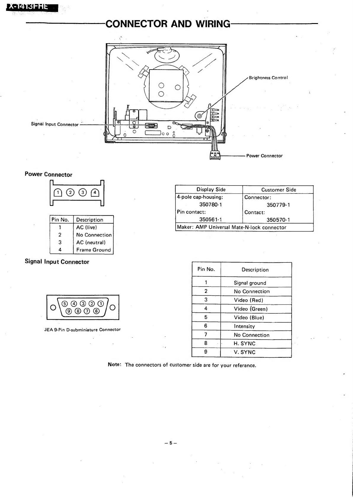
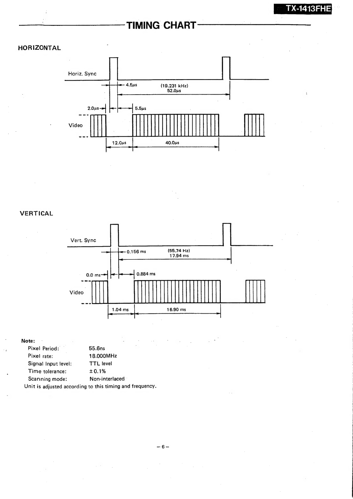
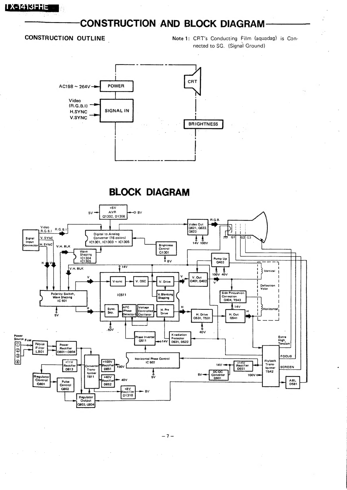
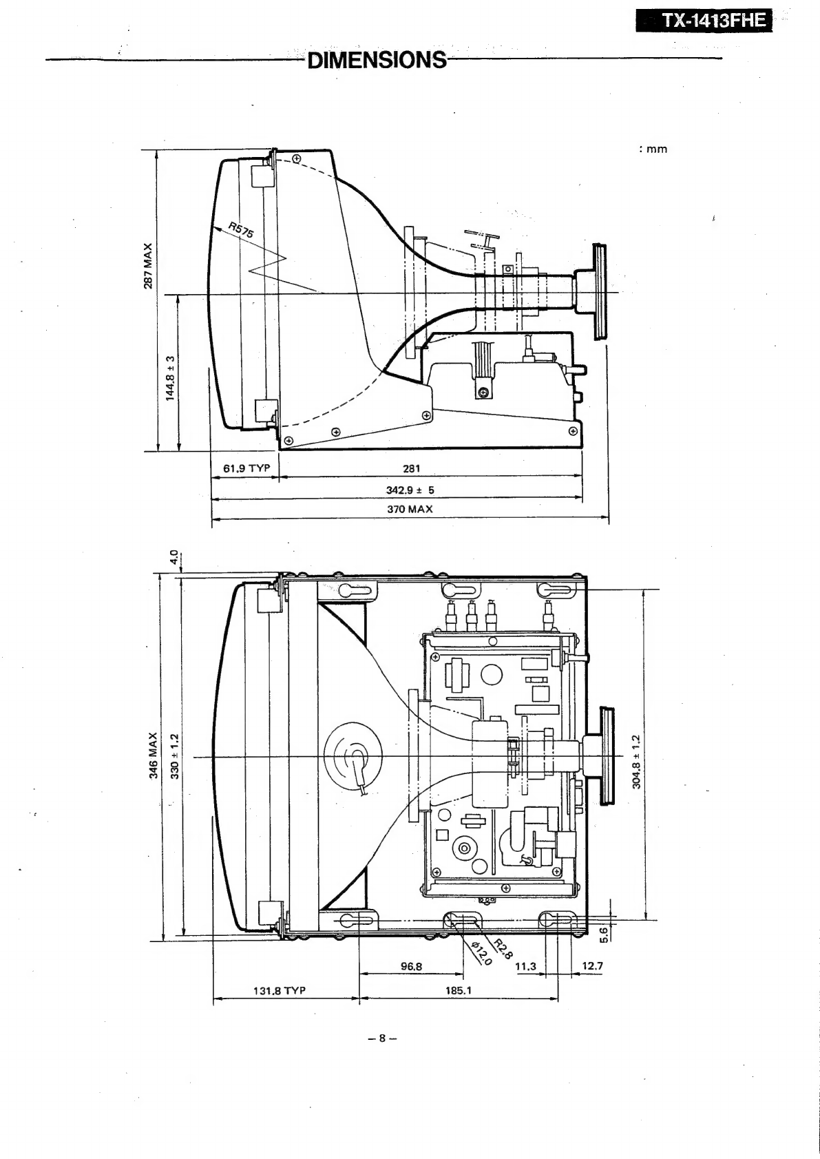
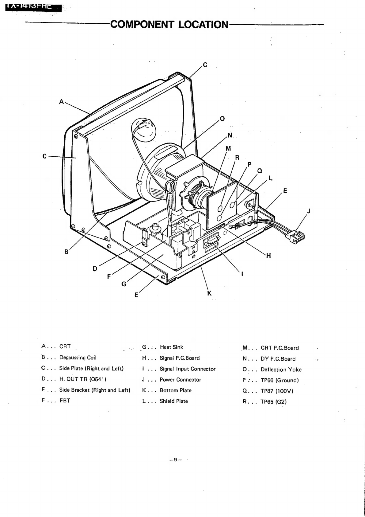
Panasonic TX-1413FHE User manual
Other Panasonic Monitor manuals

Panasonic
Panasonic WVLD1500 - 15" LCD Monitor User manual

Panasonic
Panasonic TH-80LF50ER User manual

Panasonic
Panasonic BT-LH2550 User manual

Panasonic
Panasonic TH-37PW7BX User manual

Panasonic
Panasonic TH-50PHW6BX User manual

Panasonic
Panasonic WVCM1470 - COLOR MONITOR User manual

Panasonic
Panasonic TH-L37U20R User manual

Panasonic
Panasonic CF-VDL01 User manual

Panasonic
Panasonic TH-37PR10B User manual

Panasonic
Panasonic PANASYNC E15 User manual

Panasonic
Panasonic 58PF12UK - TH - 58" Plasma Panel User manual

Panasonic
Panasonic TH-85VX200C User manual

Panasonic
Panasonic TH-42PF30U User manual

Panasonic
Panasonic M-900 Series User manual

Panasonic
Panasonic TH-42PWD4A User manual

Panasonic
Panasonic BT-H1700P User manual

Panasonic
Panasonic Viera TH-42PWD4 User manual

Panasonic
Panasonic TH-80LFB70U User manual

Panasonic
Panasonic Viera TH-37PH10 Setup guide

Panasonic
Panasonic GT01 User manual