manuals.online logo
Brands
  1. Home
  2. •
  3. Brands
  4. •
  5. Panasonic
  6. •
  7. Multiplexer
  8. •
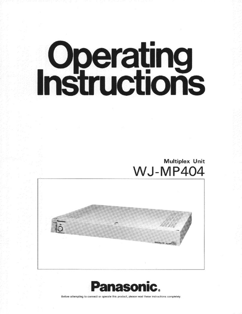
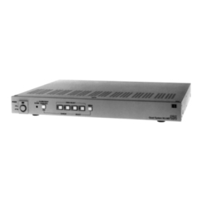
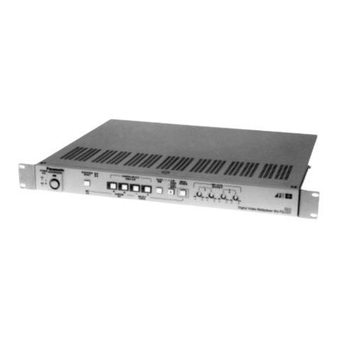
  9. Panasonic WJFS216 - SWITCHER User manual

Panasonic WJFS216 - SWITCHER User manual

rating
ructions
Video
Multiplexer
WJ-FS216
Panasonic.
Balore
attempling
ro
connect
ar
operate
rthig
product,
plaasé
read
these
insrruastions
camplately
CONTENTS
PREFACE
m
Gusto
bad
oh
m
cedo
paar
rA
ED
ppp
UN
ep
LN
I
AE
co
Lud
etes
pt
ecce
ete
doo
1
FEATURES
x
EL
1
IMPORTANT-
NOTICES
vaticinia
teste
v
ra
eh
eer
cee
onan
t
hec
tont
ete
Aceto
id
d
d
qui.
tib
a
ES
TAA
a
d
a
ap
quis
1
PRECAUTIONS
e
——————m————M———
eR
TN
net
1
MAJOR
OPERATING
CONTROLS
AND
THEIR
FUNCTIONS
"re
——€—
2
RACK
MOUNTING
raara
pee
cece
be
ots
LP
PO
FO
Pa
Ote
feri
t
rede
Oe,
til
ates
eue
IURI
5
SETTING
UP
THE
MENU
osstievetf
verum
t
enu
OE
coat
biu
a
ADS
Cho
e
prp
eta
Fen
Me
ted
oae
Lv
mra
tat
REAR
A
6
A.
Setting
up
MENU
1
OF
3
in
the
MULTIPLEX
Modo
ieee
Onc
ante
REOR
URL
Rc
7
B.
Setting
up
MENU
2
OF
3
in
the
MULTIPLEX
Mode:
«ioi
eo
e
air
eer
te
re
tg
reta
ett
vince
tica
ai
p
reote
bwin:
9
C.
Setting
up
MENU
3
OF
3
in
the
MULTIPLEX
ModE
het
n
te
o
o
PR
Rd
ef
S
E
TEE
a
SESA
EN
oia
o
D
eee
rli
en
aa
10
A.
Setting
up
MENU
1
OF
3
in
the
MULTISCREEN
mode
ico
Cote
ito
co
tnt
Cert
ri
o
aont
epa
en
E
ni
tel
teres
12
E.
Setting
up
MENU
2
OF
3
in
the
MULTISCHREEN
triod8-.
oid
IE
eerte
era
etu
tne
THER
et
ng
ala
MR
Deux
Pith
ba
13
C.
Setting
up
MENU
3
OF
3
in
the
MULTISCREEN
mode
etes
ee
estet
tpa
a
obe
e
e
dc
p
ERR
Pb
anite
e
eda
es
13
SETTING
UP
THE
TIME
LAPSE
VCR
dosi
UN
"e
RON
A
Ene
os
ts
canes
13
OPERATION
.
m"
TEE
MERE
MULTIPLEX
Mode
Snape
rot
etas
tera
codices
fuh
edet
cad
Mead
a
slack
ne
mI
Nerea
E
s
teil
E
EA
dod
vd
14
MOUETISOB
OGG
iore
ensure
Bero
QU
RP
DS
ERR
EORR
DEC
LASER
EE
T
oh
Le
PEE
CO
SUE
Pv
oi
upto
dd
Gad
eta
oe
d
in
19
CONNECTION
zi
reuse
ose
Eventa
bts
Fe
CES
vin
tree
a
Prec
esed
Med
da
s
es
rm
rona
ORL
caeci
dvd
a
Chro
rad
21
SPECIFICATIONS
aseeseen
"etr
MEER
25
STANDARD
ACCESSORIES
eie
situe
nri
a
eda
RON
ete
Pe
a
dn
avc
Feud
ect
doen
bs
VI
AN
EA
25
CAUTION
CAUTION:
Before
attempting
to
connect
or
operate
this
product,
please
read
the
label
on
the
bottom.
CAUTION:
TO
REDUCE
THE
RISK
OF
ELECTRIC
SHOCK,
DQ
BM...
70^————-——7—77———————-
For
U.S.A
.-.,
Warning:
This
equipment
generates
and
uses
radio
frequency
ener-
gy
and
if
not
installed
and
used
properly,
i.e.,
in
Strict
accordance
with
the
instruction
manual,
may
cause
harmful
interference
to
radio
communications.
It
has
been
tested
and
found
to
comply
with
the
limits
for
a
Class
A
computing
device
pursuant
to
Subpart
J
of
Part
15
of
FCC
Rules,
which
are
designed
to
provide
reasonable
protection
against
such
interference
when
operated
in
a
commercial
environment.
NOT
REMOVE
COVER
(OR
BACK).
NO
USER
SER-
VICEABLE
PARTS
INSIDE.
REFER
SERVICING
TO
QUALIFIED
SERVICE
PER-
SONNEL.
The
lightning
flash
with
arrowhead
sym-
bol,
within
an
equilateral
triangle,
is
intended
to
alert
the
user
to
the
pres-
ence
of
uninsulated
"dangerous
voltage"
within
the
product's
enclosure
that
may
be
of
sufficient
magnitude
to
constitute
a
L2lll2l20.--.--2-2-22222—-2-2--2-22-
—
——
——
—
——
——M—À
— —
ee
——
——
————
mm
————————
———
a
—
E
a
SA
1965
fisk
of
electric
chock
to
persons.
Mis
opi
rumoer
of
this
product
may
be
found
on
the
bot
f
n
f
.
You
should
note
the
serial
number
of
this
unit in
the
space
The
exclamation
point
within
an
equilat-
provided
and
retain
this
book
as
a
permanent
record
of
your
eral
triangle
is
intended
to
alert
the
user
purchase
to
aid
identification
in
the
event
of
theft.
to
the
presence
of
important operating
and
maintenance
(servicing)
instructions
Model
No.
WJ-FS216
.
inthe
literature
accompanying
the
appli-
ance.
Serial
No.
SA
1966
WARNING:
TO
PREVENT
FIRE
OR
ELECTRIC
SHOCK
HAZARD,
DO
NOT
EXPOSE
THIS
APPLIANCE
TO
RAIN
OR
MOISTURE.
PREFACE
NN
The
WJ-FS216
Video
Multiplexer
is
designed
to
pick
up
the
field
signals
from
video
cameras
and
record
the
camera
images
on
a
time
lapse
VCR.
The
pictures
of
up
to
16
cameras
can
be
monitored
in
single,
quad
or
multi
picture
mode.
Camera/pictures
can
be
called
from
the
time
lapse
VCR
output
by
a
title
added
to
the
camera
picture
or
by
simply
pressing
the
selection
but-
ton
for
the
respective
camera.
FEATURES
The
WJ-FS216
Video
Multiplexer
is
designed
to
pick
up
the
field
signals
from
video
cameras
and
record
the
camera
images
on
a
time
lapse
VCH.
Up
to
16
cameras
(black
&
white
or
color
cameras)
can
be
connected
to
the
WJ-FS216
regardless
of
whether
the
camera
signals
are
synchronized
or
not.
The
functions
of
the
two
available
modes,
MULTIPLEX
and
MULTISCR,
are
as
follows:
e
MULTIPLEX
mode
1.
Monitoring
sequential
or
single
(spot)
pictures
and
simultaneously
recording
them
on
the
time
lapse
VCR.
2.
Easy
selection
of
playback
picture
from
the
time
lapse
VCR
and
displaying
it
as
a
single
(spot)
or
multt
picture
(quad,
3x3,
or
4x4)
by
simply
pushing
the
camera
selection
button.
The
Quad
Shift
function
allows
you
to
shift
between
up
to
four
quad
pictures
(each
consisting
of
4
pic-
tures).
3.
Pauses
can
be
inserted
in
the
pictures
reproduced
by
the
time
lapse
VCR
(STILL
ON
mode).
In
multi
picture
mode,
pauses
can
also
be
inserted
in
any
monitored
pictures,
and
single
spot
pictures
can
be
zoomed
up
to
twofold.
*
MULTISCR
mode
1.
You
can
monitor
sequential,
single
(spot)
or
multi
pictures
(quad,
3x3,
or
4x4)
and
record
them
simul-
taneously
on
the
time
lapse
VCR.
2.
You
can
switch
between
display
patterns
(spot,
quad,
3x3,
or
4x4)
by
simply
pressing
any
of
the
camera
selection
buttons
1
to
3.
3.
The
Quad
Shift
function
allows
you
to
display
up
to
four
quad
pictures
(each
consisting
of
4
pictures)
on
one
screen.
4.
You
can
pause
(STILL
ON
mode)
or
zoom
the
piay-
back
picture.
In
multi
picture
mode,
all
pictures
monitored
can
be
paused,
but
only
one
specified
picture
can
be
zoomed.
«
Common
to
both
modes
1.
Remote
control
2.
An
alarm
beeps
to
indicate
that
a
cable
is
discon-
nected.
3.
Memory
backup
(approx.
72
hours)
for
menus.
IMPORTANT
NOTICES
The
playback
picture
of
the
Time
Lapse
VCR
with
linear
mode
may
be
disturbed
by
another
channel
picture.
In
this
case
playback
again
for
the
dis-
turbed
picture
scene
of
playback
VCR
without
linear
mode.
The
WJ-FS10
cannot
play
back
tapes
recorded
on
the
WJ-FS216.
These
Operating
Instructions
explain
the
operating
procedure
when
using
the
AG-6730
Time
Lapse
VCR
or
equivalent.
This
unit
does
not
accept
the
camera
motion
detec-
tor
alarm
signal.
Do
not
attempt
to
disassemble
the
unit.
In
order
to
prevent
electrical
shock,
do
not
remove
screws
or
Covers.
There
are
no
user-serviceable
parts
inside.
Do
not
abuse
the
unit.
Avoid
striking,
shaking
etc.
It
could
be
damaged
by
improper
handling
or
stor-
age.
Do
not
use
strong
or
abrasive
detergents
when
cleaning
the
unit
body.
Do
not
expose
the
unit
to
water
or
moisture,
and
do
not
operate
it
in
wet
or
humid
areas.
Do
not
use
the
unit
in
an
extreme
environment
where
either
high
temperature
or
high
humidity
exist.
Handle
the
unit
with
care.
Take
immediate
action
if
ever
the
unit
does
become
wet.
Tune
the
power
off
and
refer
servicing
to
quali-
fied
service
personnel.
Moisture
can
damage
the
unit
and
also
create
a
danger
of
electric
shock.
Use
the
unit
under
conditions
where
temperature
is
within
—10°C
to
+50°C
(14°F
to
122°F),
and
humidity
is
below
9096.
When
installing
the
unit
in
the
rack,
it
is
recommended
to
install
the
fan.
e
The
input
power
source
is
120
V
AC,
60
Hz.
Refer
all
installation
work
to
qualified
service
per-
sonnel
or
system
installers.
MAJOR
OPERATING
CONTROLS
AND
THEIR
FUNCTIONS
Osgial
Video
MultipiexerWw
J-F
S
21
6
.
Power
ON/OFF
Switch
(POWER
ON/OFF)
This
switch
is
used
to
turn
the
power
of
this
unit
on
or
off.
The
POWER
indicator
lights
when
the
power
of
this unit
is
on.
.
Alarm
LED
(ALARM)
This
LED
flashes
while
the
alarm
signal
is
received.
It
lights
in
the
following
cases:
e
When
the
ALARM/REMOTE
connector
receives
the
alarm
reset
signal.
*
When
the
alarm
reset
time
specified
for
AUTO
RESET
in
MENU
1
OF
3
has
elapsed
(in
multi-
screen
mode).
To
turn
off
the
LED,
press
the
ALARM
RESET
but-
ton.
.
Sequence/Alarm
Reset
Button
(SEQUENCE/ALARM
RESET)
This
button
activates
SEQUENCE
mode
when
the
MODE
SELECT/CAMERA
SELECT
switch
is
in
CAMERA
SELECT
position.
During
the
alarm
is
activating,
this
button
is
activat-
ed
as
the
ALARM
RESET
button
regardless
of
the
.
MODE
SELECT/CAMERA
SELECT
switch
position.
Sequence
Button
This
button
is
used
to
activate
the
sequence
mode.
In
this
mode,
a
series
of
pictures
is
displayed
in
succession
on
the
monitor
screen
with
the
order
and
duration
you
set.
Alarm
Reset
Button
This
button
is
used
to
cancel
an
active alarm.
Press
this
button
during
the
alarm
is
activating
so
that
the
alarm
is
reset
and
return
to
the
condition
before
the
alarm
function
activates.
4.
Zoom/Multiscreen/Quad
Shift
Button
(ZOOM/
MULTISCREEN/QUAD
SHIFT)
This
button
has
three
functions.
The
functions
change
according
to
the
position
of
the
MODE
SELECT/CAMERA
SELECT
switch
as
follows:
When
the
MODE
SELECT/CAMERA
SELECT
switch
is
in
CAMERA
SELECT
position,
this
button
works
as
the
MULTISCREEN
or
the
QUAD
SHIFT
button.
When
the
MODE
SELECT/CAMERA
SELECT
switch
is
in
MODE
SELECT
position,
this
button
works
as
the
ZOOM
button.
¢
MULTISCREEN
button
Pressing
this
button
changes
the
picture
(cam-
era
picture
or
playback
picture
from
the
time
lapse
VCR)
to
four
(quad),
3x3
or
4x4
(multi)
pictures.
*
QUAD
SHIFT
button
Pressing
this
button
when
monitoring
a
quad
picture
shifts
to
another
of
up
to
four
quad
pic-
tures.
See
page
16
for
details.
*
ZOOM
button
Pressing
this
button
zooms
up
a
specified
por-
tion
of
the
monitored
picture.
See
page
18
or
20
for
details.
5.
Camera
Selection
Button
(1...16,
EE,
GB,
&B,
CAMERA/VCR,
A, V,
<,
>,-,
+,
SET,
STILL
ON)
When
the
MODE
SELECT/CAMERA
SELECT
switch
is in
CAMERA
SELECT
position,
these
buttons
can
be
used
to
select
the
desired
camera.
The
LED
in
the
button
lights
to
indicate
the
number
of
the
selected
camera.
Except
for
buttons
4,
5,
6
and
7,
the
function
of
these
buttons
changes
when
the
MODE
SELECT/
CAMERA
SELECT
switch
is
set
to
MODE
SELECT
position.
The
functions
of
each
button
are
as
fol-
lows:
Button
No.1
(G5)
When
the
MULTIPLEX
mode
is
selected,
the
play-
back
picture
is
displayed
as
a
quad
picture.
When
the
MULTISCR
mode
is
selected,
the
camera
picture
is
displayed
as
a
quad
picture.
Button
No.2
(G3)
When
MULTIPLEX
mode
is
selected,
the
monitor
screen
is
divided
into
nine
fields
for
displaying
playback
piciures.
When
MULTISCR
mode
is
selected,
the
screen
is
divided
into
nine
fields
for
displaying
camera
pic-
tures.
Button
No.3
(&
)
When
MULTIPLEX
mode
is
selected,
the
monitor
screen
is
divided
into
sixteen
fields
for
displaying
playback
pictures.
When
MULTISCR
mode
is
selected,
the
screen
is
divided
into
sixteen
fields
for
displaying
camera
pictures.
Button
No.8
(CAMERA
/
VCR)
This
button
is
used
to
select
the
camera
picture
or
playback
picture
to
be
displayed
on
the
monitor.
While
the
playback
picture
is
displayed,
the
CAM-
ERA/VCR
indicator
lights
to
indicate
that
VCR
is
selected.
Button
No.9
(^)
Moves
the
*+"
sign
(zoom
cursor)
upward.
Use
this
button
to
move
the
cursor
on
the
menu.
Button
No.10
(V)
Moves
the
“+”
sign
(zoom
cursor)
downward.
Use
this
button
to
move
the
cursor
on
the
menu.
Button
No.11
(«J)
Moves
the
"+"
sign
(zoom
cursor)
to
the
left.
Use
this
button
to
move
the
cursor
on
the
menu.
Button
No.12
(©)
Moves
the
“+”
sign
(zoom
cursor)
to
the
right.
Use
this
button
to
move
the
cursor
on
the
menu.
Button
No.13
(-)
Moves
the
character
selection
cursor
in
reverse
alphabetical
order.
Button
No.14
(+)
Moves
the
character
selection
cursor
in
alphabeti-
cal
order.
10.
11.
12.
Button
No.15
(SET)
This
button
is
used
as
the
SET
button
in
setting
pro-
cedures.
Button
No.16
(STILL
ON)
This
button
is
used
to
pause
the
picture
on
the
screen
and
monitor
the
still
picture
(STILL
ON
mode).
.
CAMERA/VCR
Indicator
While
this
indicator
is
lit,
the
playback
picture
can
be
displayed
on
the
monitor.
.
STILL
ON
indicator
While
this
indicator
is
lit,
the
picture
can
be
made
still
by
pressing
one
of
the
camera
selection
but-
tons.
.
MODE
SELECT/CAMERA
SELECT
switch
This
switch
is
used
to
change
the
functions
of
the
buttons
on
the
front
panel.
When
this
switch
is
positioned
at
CAMERA
SELECT,
the
buttons
operate
as
indicated
by
the
printed
but-
ton
name
in
the
gray
square.
When
this
switch
is
positioned
at
MODE
SELECT,
the
buttons
operate
normally
as
indicated
by
the
printed
button
name.
.
Menu
button
(MENU)
This
button
is
used
to
display
the
setup
menu.
Pressing
this
button
for
2
seconds
or
longer
will
dis-
play
the
menu
on
the
monitor
screen.
To
return
to
monitoring,
press
this
button
again
for
2
seconds
or
longer.
Camera
Input
Connectors
These
connectors
input
the
composite
video
signal
from
the
cameras.
Note:
If
the
video
signal
is
interrupted
due
to
a
cable
disconnection,
for
example,
the
message
“CHXXLOSS”
is
displayed
and
the
buzzer
beeps.
Check
that
the
connections
are
correct
and
firm,
then
input
the
video
signal
again
or
press
the
SEQUENCE/ALARM
RESET
button.
This
stops
the
buzzer
and
resets
the
alarm
and
the
unit
to
the
condition
before
the
video
signal
was
interrupted.
Caution:
The
picture
may
be
disturbed
when
switching
non-synchronized
camera
signals.
This
can
be
avoided
by
synchronizing
the
camera
signals.
Camera
Output
Connectors
(CAMERA
OUT)
The
signals
from
the
input
cameras
are
loopéd
through
at
these
connectors,
Connecting
a
coaxial
cable
will
automatically
select
high
impedance
video
loop.
Playback
Input
Connector
(PLAY
IN)
The
playback
signal
from
the
time
lapse
VCR
is
supplied
to
this
connector.
This
connector
works
only
when
MULTIPLEX
mode
is
selected.
13.
14.
15.
16.
17.
18.
Recording
Output
Connector
(REC
OUT)
When
MULTIPLEX
mode
is
selected,
the
recording
signal
for
the
time
lapse
VCR
is
supplied
from
this
connector.
When
MULTISCR
mode
is
selected,
the
multiscreen
picture
video
signal
for
the
time
lapse
VCR
is
sup-
plied
from
this
connector.
Caution:
In
MULTIPLEX
mode,
the
unit
adds
codes
to
video
signals
during
vertical
blanking
while
they
are
recorded
on
the
VCR.
This
is
the
reason
why
video
signals
with
a
certain
code
are
not
recordable
during
vertical
blanking.
Monitor
Output
Connector
(MONITOR
OUT)
This
connector
supplies
a
composite
video
signal
for
monitoring.
Sequential
picture,
time
lapse
VCR
playback
pictures
and
the
menus
can
be
displayed
on
à
connected
monitor.
Camera
Switching
Signal
Input
Connector
(CAMERA
SW
IN)
The
camera
switching
signal
from
the
time
lapse
VCR
is
supplied
to
this
connector.
This
connector
works
only
when
the
MULTIPLEX
mode
is
selected.
Note:
When
REC
MODE
is
set
to
T/L
but
no
camera
switching
signal
is
supplied,
time
lapse
record-
ing
will
not
work
properly.
ALARM/REMOTE
Connector
This
connector
is
used
for
remote
controlling.
You
can
control
the
following
functions:
e
Alarm
Output
Recover
Input
MULTISCREEN
SEQ
Receiving
the
alarm
input
signal
at
the
camera
site,
or
the
remote
input
signal
for
the
camera
selection
buttons.
Ground
Terminal
Power
Cord
RACK
MOUNTING
To
install
the
WJ-FS216
Video
Multiplexer
in
an
EIA
19-
inch
rack,
use
the
rack
mounting
brackets
(provided)
and
eight
screws
(provided,
M3x10).
1.
Turn
off
the
power
of
the
unit.
2.
Remove
the
four
screws
fixing
the
rubber
legs
and
remove
the
four
rubber
legs
from
the
unit.
Remove
four
rubber
legs.
3.
Attach
the
rack
mounting
brackets
on
both
sides
and
fix
them
with
eight
screws
(provided).
Eight
screws
(Provided)
Fix
the
rack
mounting
brackets
4.
Install
the
unit
in
the
rack
with
four
screws
(to
be
procured
locally).
Cautions:
1.
Leave
one
space
free
both
above
and
below
the
unit,
or
install
a
cooling
fan
in
the
rack.
2.
If
the
rack
is
subject
to
vibrations,
secure
the
rear
of
the
unit
to
the
rack
using
additional
rack
mounting
brackets
(to
be
procured
locally).
SETTING
UP
THE
MENU
*
Before
the
settings
1.
Confirm
the
cameras
and
peripherals
are
connect-
ed
correctly
and
firmly.
2.
Turn
the
power
of
this
unit
and
connected
peripher-
als
on.
`
1.
Displaying
the
Menus
1.
Set
the
MODE
SELECT/CAMERA
SELECT
switch
to
MODE
SELECT
position.
Bb
2.
Press
the
MENU
button
for
2
seconds.
MENU
1
OF
3
appears
on
the
monitor.
MENU
L]
2.
Selecting
the
system
mode
This
unit
can
be
adapted
to
specific user
needs.
Before
performing
other
settings,
follow
the
steps
below
to
select
the
system
mode
that
best
meets
your
requirements.
1.
After
displaying
MENU
1
OF
3,
use
buttons
9
-
12
(A,
V,
<,
©}
to
display
MENU
3
OF
3.
The
func-
tions
of
these
buttons
in
the
menu
are
as
follows:
å
<
m
e
Button9
(A)
Moves
the
cursor
upward.
Pressing
this
button
when
the
cursor
is
on
the
first
menu
item
displays
the
previous
menu.
e
Button
10
(V)
Moves
the
cursor
downward.
Pressing
this
button
when
the
cursor
is
on
the
last
menu
item
displays
the
next
menu.
*
Button
11
(<4)
Moves
the
cursor
to
the
left
or
upward.
Pressing
this
button
when
the
cursor
is
on
the
first
menu
item
displays
the
previous
menu.
*
Button
12
(D)
Moves
the
cursor
to
the
right
or
downward.
Pressing
this
button
when
the
cursor
is
on
thé
last
menu
item
displays
the
next
menu.
2.
3.
*
MENU1
OF
3
*
DYNAMIC
REC
OFF
ALARM
BUZZER
28
ALARM
OUTPUT
2s
REC
MODE
4FIELDS
PLAYBACK
MODE
FIELD
*
MENU2
OF
3
*
TITLE SETUP
*
TITLE
POSITION
*
TITLE
DISPLAY
ON
STILL/ALARM
DISP
ON
*
MENU3
OF
3
*
BORDER
WHITE
AUTO SKIP
OFF
SEQUENCE
SETUP
*
START
SCREEN
l-SEQ
SYSTEM
MODE
MULTIPLEX
Move
the
cursor
to
SYSTEM
MODE
by
pressing
but-
ton
9
(A)
or
10
(V
).
Select
MULTIPLEX
or
MULTISCR
by
pressing
but-
ton
13
(-)
or
14
(4).
MULTIPLEX:
Select
this
mode
to
monitor
the
camera
pictures
or
píayback
pictures.
In
MULTIPLEX
mode
you
can
perform
the
following
monitoring
operations:
1.
Camera
picture
*
Single
spot
picture
e
Single
spot
picture
sequence
2.
Playback
picture
oí
the
time
lapse
VCR
Single
spot
picture
Single
spot
picture
sequence
Multi
spot
picture
Quad
picture
sequence
Still
single
spot
picture
Still
multi
spot
picture
Single
spot
picture
zoom
e
9
9 o
9
9*9
è
MULTISCR:
Select
this
mode
to
monitor
the
camera
pictures.
In
MULTISCR
mode
you
can
perform
the
following
monitoring
operations:
1.
Camera
picture
Single
spot
picture
Multi
spot
picture
Single
spot
picture
sequence
Quad
picture
sequence
Still
mutti
spot
picture
Multi
spot
picture
zoom
The
menu
content
is
different
depending
on
the
selected
mode.
(Compare
MENU
1
OF
3
for
MUL-
TIPLEX
and
MULTISCR
mode
below.)
This
is
described
in
more
detail
on
the
following
pages.
*
MENU1
OF
3
*
DYNAMIC
REC
ALARM
BUZZER
ALARM
OUTPUT
REC
MODE
4FIELDS
PLAYBACK
MODE
FIELD
MULTIPLEX
mode
*
MENU1
OF
3
*
-608
-
FM
EE
ALARM
BUZZER
23
AUTO
RESET
ALARM
OUTPUT
2s
MULTISCR
CH
SET
*
MULTISCR
mode
4.
Press
the
MENU
button
to
return
to
monitoring.
*
How
to
Operate
the
Menus
To
select
the
desired
item,
press
the
9-12
(A,
V.
<,
>)
buttons.
Each
time
you
press
the
button,
the
cursor
moves
to
the
parameter
ol
selected
item.
To
set
or
select
the
desired
parameter
of
selected
item,
press
the
13
(-)
or
14
(+)
button.
Note:
Some
items
have
a
submenu
(for
example,
TITLE
SETUP
in
MENU
2
OF
3).
To
make
set-
ting
in
a
submenu,
press
button
15
(SET).
7.
A.
Setting
up
MENU
1
OF
3
in
the
1.
1.
MULTIPLEX
mode
The
content
of
MENU
1
OF
3
in
MULTIPLEX
mode
is
as
shown
below.
*
MENU1
OF
3
*
DYNAMIC
REC
ALARM
BUZZER
ALARM
OUTPUT
REC
MODE
4FIELDS
PLAYBACK
MODE
FIELD
DYNAMIC
REC
When
ON
is
selected
for
DYNAMIC
REC,
the
cam-
era
picture
of
a
channe!
that
is
received
an
alarm
signal
is
recorded
with
more
frames
than
normal.
If
the
alarm
signal
is
received
to
multiple
channels,
the
pictures
of
all
these
channels
are
recorded.
Move
the
cursor
to
the
DYNAMIC
REC
parameter.
ele
fe
Ec
å
< >
2.
Select
ON
or
OFF.
ON:
The
video
signa!
of
the
channel
that
is
received
the
alarm
signal
is
recorded
with
more
frames
than
normal.
If
the
alarm
signal
is
received
to
multiple
channels,
the
pictures
of
all
these
channels
are
recorded.
l
OFF:
Sequential
pictures
are
recorded
from
chan-
nels
number
1
to
16
regardless
of
any
channels
receiving
the
alarm
signal.
The
factory
setting
is
OFF.
*
|f
you
do
not
change
any
other
parameters,
press
the
MENU
button
for
2
seconds.
The
setup
menu
is
closed
and
the
display
returns
to
the
monitoring
picture.
If
turning
the
power
off,
make
sure
to
finalize
your
settings
by
pressing
the
MENU
button.
Otherwise
the
new
settings
will
not
be
stored
and
the
previous
settings
remain
in
effect.
Turn
the
power
off
after
the
monitoring
picture
appears
on
the
display.
2.
2.
ALARM
BUZZER
The
buzzer
beeps
when
this
unit
receives
the
alarm
signal.
You
can
adjust
the
buzzer
time
between
1
and
60
seconds
by
changing
the
ALARM
BUZZER
parameter.
.
Move
the
cursor
to
the
ALARM
BUZZER
parameter.
.
Select
the
buzzer
time.
OFF:
The
alarm
buzzer
does
not
beep
when
the
alarm
signal
is
received.
1-30,
60S:
The
buzzer
keeps
on
beeping
for
the
duration
you
set.
The
letter
"S"
stands
for
sec-
onds.
The
factory
setting
is
28.
*
MENU1
OF
3
*
DYNAMIC
REC
OFF
ALARM
BUZZER
28
ALARM
OUTPUT
28
REC
MODE
4FIELDS
PLAYBACK
MODE
FIELD
ALARM
OUTPUT
When
alarm
is
received,
the
alarm
signal
is
sup-
plied
to
the
other
device
through
the
ALARM/REMOTE
connector.
You
can
adjust
the
duration
the
alarm
signal
is
output
between
1
and
60
seconds.
*
MENU1
OF
3
*
DYNAMIC
REC
OFF
ALARM
BUZZER
2s
ALARM
OUTPUT
28
REC
MODE
4FIELDS
PLAYBACK
MODE
FIELD
Select
the
duration
the
alarm
signal
is
output.
1-30,
60S:
The
alarm
signal
is
output
for
the
dura-
tion
you
set.
The
letter
"S"
stands
for
seconds.
The
factory
setting
is
2S.
4.
REC
MODE
The
recording
mode
can
be
set
to
4-90
fields
or
time
lapse
recording.
.
Move
the
cursor
to
the
REC
MODE
parameter.
*
MENU1
OF
3
*
DYNAMIC
REC
OFF
ALARM
BUZZER
2s
ALARM
OUTPUT
2s
AFIELDS
REC
MODE
PLAYBACK
MODE
FIELD
.
Select
the
recording
mode.
4-90
FIELDS:
The
output
signal
to
be
recorded
on
the
VCR
is
switched
every
fields
you
have
set.
T/L:
The
recording
output
signal
is
supplied
to
the
VCR
for
time
lapse
recording.
The
factory
setting
is
4
FIELDS.
Note:
When
T/L
is
selected
and
no
camera
switching
signal
supplied,
there
will
be
no
correct
time
lapse
recording.
In
this
case,
either
supply
the
camera
switching
signal
or
select
4
-
90
fields
in
REC
mode
for
normal
recording.
PLAYBACK
MODE
This
unit
can
play
back
tape
recorded
by
WJ-FS20
or
WJ-FS10.
.
Move
the
cursor
to
the
PLAYBACK
MODE
parame-
ter.
*
MENU1
OF
3
*
DYNAMIC
REC
OFF
ALARM
BUZZER
28
ALARM
OUTPUT
28
REC
MODE
4FIELDS
PLAYBACK
MODE
FIELD
.
Select
the
tape
type.
FIELD:
To
replay
tapes
recorded
on
this unit
or
the
WJ-FS20.
FS10:
To
replay
tapes
recorded
on
the
WJ-FS10.
The
factory
setting
is
FIELD.
Notes:
*
The
WJ-FS10
cannot
play
back
tapes
recorded
on
the
WJ-FS216.
e
When
playing
back
a
tape
recorded
on
the
WJ-
FS10,
note
that
the
channel
number
for
record-
ing
and
playback
is
different.
Display
the
4x4
screen
to
check
the
channel
number
and
select
the
desired
picture.
B.
Setting
up
MENU
2
OF
3
in
the
MULTIPLEX
mode
The
content
of
MENU
2
OF
3
is
the
same
depend-
ing
on
the
parameter
selected
for
SYSTEM
MODE
in
MENU
3
OF
3.
An
example
is
shown
below.
1.
TITLE
SETUP
A
title
consisting
of
up
to
8
alphanumeric
characters
*
MENU2
OF
3
*
TITLE
SETUP
*
TITLE
POSITION
*
TITLE
DISPLAY
ON
STILL/ALARM
DISP
ON
i.
Move
the
cursor
to
SETUP
in
TITLE
SETUP.
*
MENU2
OF
3
*
TITLE
SETUP.
*
TITLE
POSITION
*
TITLE
DISPLAY
ON
STILL/ALARM
DISP
ON
2.
Press
button
15
(SET).
The
TITLE
menu
appears
on
the
monitor.
**
TITLE
**
.
Move
the
cursor
to
the
channel
number
for
which
a
title
is
to
be
edited
by
pressing
buttons
9-12
(A,
V,
<J,
>).
.
Select
the
first
character
for
the
title
by
pressing
button
13
(-)
or
14
(4).
Characters
for
the
title
can
be
selected
fram
the
fol-
lowing
list:
ABCDEFGHIJKLM
NOPORSTUVWXYZ
0123456789
CIE?
'"#E()
*+,
-./:;.(space
mark)
-9-
.
After
selecting
the
first
character,
press
button
12
(E).
Then
select
the
second
character.
.
Repeat
steps
3
to
5
above
to
complete
the
title.
.
Repeat
step
3
to
6
to
edit
the
other
channels.
.
Press
button.
15
(SET)
to
finalize
the
character
selection.
The
title
is
set,
and
the
display
returns
to
MENU
2
OF
3.
To
erase
a
specific
character
T;
Select
a
character
to
be
erased.
2.
Select
"*"
(space
mark)
to
erase
the
character,
To
erase
the
title
of
a
specific
channel
1.
Move
the
cursor
to
the
channel
number
whose
title
is
to
be
erased.
2.
Press
buttons
13
(-)
and
14
(+)
simultaneously.
2.
1.
TITLE
POSITION
You
can
select
the
position
on
the
monitor
where
you
want
the
title
to
be
displayed.
Move
the
cursor
to
POSITION
in
TITLE
POSITION.
*
MENU2
OF
3
*
TITLE
SETUP
*
TITLE
iPOSITION,
*
TITLE
DISPLAY
ON
STILL/ALARM
DISP
ON
2.
Press
button
15
(SET).
The
TITLE
POSITION
setting
is
on
stand
by.
3.
Select
the
position
where
the
title
is
to
be
displayed
by
pressing
button
11
(«1)
or
12(f).
You
can
select
any
of
the
12
positions
shown
in
the
diagram
above.
.
Press
button
15
(SET)
to
finalize
the
title
position.
The
title
position
is
set,
and
the
display
returns
to
MENU
2
OF
3.
Note:
All
channel
titles
will
be
displayed
in
the
same
position.
You
cannot
specify
a
different
position
for
each
title.
.
TITLE
DISPLAY
This
parameter
lets
you
decide
whether
or
not
to
have
the
title
displayed.
.
Move
the
cursor
to
the
TITLE
DISPLAY
parameter.
*
MENU2
OF
3
*
TITLE SETUP
*
TITLE
POSITION
*
TITLE
DISPLAY
ON
STILL/ALARM
DISP
ON
.
Select
ON
or
OFF.
ON:
Title
display
OFF:
No
title
display
The
factory
setting
is
ON.
.
STILL/ALARM
DISP
This
parameter
lets
you
decide
whether
or
not
to
have
the
word
"STILL"
displayed
when
a
picture
is
paused
by
pressing
button
16
(STILL
ON),
or
the
word
"ALARM"
when
the
unit
is
received
the
alarm
signal.
.
Move
the
cursor
to
the
STILL/ALARM
DISP
parame-
ter.
*
MENU2
OF
3
*
TITLE
SETUP
*
TITLE
POSITION
*
TITLE
DISPLAY
ON
STILL/ALARM
DISP
‘ON
.
Select
ON
or
OFF.
ON:
"STILL"
and
“ALARM”
are
displayed.
OFF:
"STILL"
and
"ALARM"
are
not
displayed.
The
factory
setting
is
ON.
-10-
C.
Setting
up
MENU
3
OF
3
in
the
MULTIPLEX
mode
The
content
of
MENU
3
OF
3
in
MULTIPLEX
mode
is
as
shown
below.
*
MENU3
OF
3
*
BORDER
WHITE
AUTO
SKIP
OFF
SEQUENCE
SETUP
*
START
SCREEN
l-SEQ
SYSTEM
MODE
MULTIPLEX
1.
BORDER
This
parameter
lets
you
select
the
color
of
the
bor-
ders
that
divide
the
screen.
.
Move
the
cursor
to
the
BORDER
parameter.
*
MENU3
OF
3
*
BORDER
AUTO
SKIP
SEQUENCE
SETUP
*
START
SCREEN
1-SEQ
SYSTEM
MODE
MULTIPLEX
.
Select
the
color
of
the
borders.
OFF:
The
borders
do
not
appear.
BLACK:
Black
borders
GRAY:
Gray
borders
WHITE:
White
borders
The
factory
setting
is
WHITE.
.
AUTO
SKIP
This
parameter
lets
you
select
automatic
skipping
of
channels
to
which
no
camera
is
connected.
.
Move
the
cursor
to
the
AUTO
SKIP
parameter.
*
MENU3
OF
3
*
BORDER
WHITE
AUTO SKIP
(OFF;
SEQUENCE
SETUP
*
START
SCREEN
1-SEQ
SYSTEM
MODE
MULTIPLEX
.
Select
ON
or
OFF.
ON:
Channels
to
which
no
camera
is
connected
are
skipped.
OFF:
No
channels
are
skipped.
The
factory
setting
is
OFF.
3.
SEQUENCE
SETUP
This
parameter
lets
you
set
the
sequential
order
and
dwell
time
for
camera
switching.
.
Move
the
cursor
to
SEQUENCE
SETUP.
4.
START
SCREEN
This
parameter
iets
you
select
a
display
pattern
for
your
startup
screen.
When
the
power
is
turned
on,
the
picture
is
displayed
in
the
selected
pattern.
1.
Move
the
cursor
to
the
START
SCREEN
parameter.
*
MENU3
OF
3
*
*
MENU3
OF
3
*
BORDER
WHITE
AUTO
SKIP
OFF
BORDER
WHITE
SEQUENCE
BETUP..*j
Orr
AUTO
SKIP
START
SCREEN
l-SEQ
SEQUENCE
SETUP
*
SYSTEM
MODE
MULTIPLEX
START
SCREEN
1-SEQ.
SYSTEM
MODE
MULTIPLEX
2.
Press
button
15
(SET).
The
SEQUENCE
menu
appears
on
the
monitor.
2.
Select
FULL
or
1-SEQ.
FULL:
A
single
picture
is
displayed.
1-SEQ:
A
sequence
of
a
single
picture
is
displayed.
Sequence
Number
Channel
Dwell
Time
The
factory
setting
is
1-SEQ.
S
VT
Wit
9CH
28
10CR
2S
11CH
28
12CH
2S
SYSTEM
MODE
See
"Selecting
the
system
mode"
on
page
6
for
set-
tings
and
procedures.
1-1CH
-25
2CH
2S
3CH
28
4CH
2S
13CH
28
l4CH
28
15CH
2S
16CH
2S
5CH
28
6CH
2S
7CH
2S
8CH
2S
3.
Move
the
cursor
to
the
sequence
number
by
press-
ing
buttons
9-12
(A,
V.
<,
D»).
4.
Select
the
channel
by
pressing
button
13
(-)
or
14
(+).
9.
Move
the
cursor
to
the
dwell
time
by
pressing
but-
ton
12
(©).
6.
Select
desired
dwell
time
by
pressing
button
13
(-)
or
14
(+).
lf
you
select
OFF
for
the
dwell
time,
the
selected
channel
is
automatically
skipped.
7.
Repeat
steps
3
to
6
to
determine
the
sequential
order
and
dwell
time.
8.
Press
button
15
(SET)
to
finalize
the
sequential
order.
The
display
returns
to
MENU
3
OF
3.
Note:
When
monitoring
a
quad
picture,
the
dwelt
time
indicated
for
sequence
numbers
1-4
refers
to
that
of
the
four
quad
pictures.
udis
2.
Press
button
15
(SET).
The
CH
SET
menu
appears
on
the
monitor.
A.
Setting
up
MENU
1
OF
3
in
the
MULTISCREEN
mode
.
AUTO
RESET
This
parameter
lets
you
set
the
time
until
the
unit
recovers
after
receiving
the
alarm
signal.
.
Move
the
cursor
to
the
AUTO
RESET
parameter.
t
MENU1
OF
3
*
AUTO
RESET
ALARM
BUZZER
ALARM
OUTPUT
MULTISCR
CH
SET
*
.
Select
the
recover
time.
OFF:
The
alarm
condition
is
maintained
until
the
ALARM
RESET
button
on
the
front
panel
is
pressed
or
the
alarm
recover
signal
from
the
time
lapse
VCR
is
supplied
to
the
ALARM/REMOTE
connector.
1-30,
60S:
The
alarm
condition
is
maintained
for
the
length
of
the
recover
time
you
set.
The
letter
"S"
stands
for
seconds.
The
factory
setting
is
60S.
.
ALARM
BUZZER
This
item
is
the
same
as
in
MENU
1
OF
3
in
the
MULTIPLEX
mode.
See
page
8
for
the
settings
and
procedures.
.
ALARM
OUTPUT
This
item
is
the
same
as
in
MENU
1
OF
3
in
the
MULTIPLEX
mode.
See
page
8
for
the
settings
and
procedures.
.
MULTISCR
CH
SET
This
parameter
lets
you
assign
the
channel
to
be
displayed
to
a
specific
divided
screen.
1.
Move
the
cursor
to
CH
SET
in
MULTISCR
CH
SET.
*
MENU1
OF
3
*
AUTO
RESET
60S
ALARM
BUZZER
-:
28
ALARM
OUTPUT
28
MULTISCR
|(CH/JSET:*
3.
Press
button
1
or
2
to
select
the
CH
SET
menu
for
MULTISCREEN.
Button
1:
Displays
the
CH
SET
menu
for
quad
and
4x4
multiscreen.
Button
2:
Displays
the
CH
SET
menu
for
3x3
multi-
screen.
**
CH
SET
**
sles
1-1CH-
2CH
3CH
4CH
5CH
6CH
7CH
8CH
.
Move
the
cursor
to
the
number
of
the
divided
screen
by
pressing
buttons
9-12
(A,
V,
<,
D»).
.
Select
the
channel
number
to
be
assigned
to
the
selected
divided
screen
by
pressing
button
13
(-)
or
14
(+).
.
Repeat
steps
4
and
5
above
to
assign
the
other
channels
to
the
divided
screens.
.
Press
button
15
(SET)
to
finalize
channel
assign-
ment.
The
display
returns
to
MENU
1
OF
3.
Setting
up
MENU
2
OF
3
in
the
MULTISCREEN
mode
MENU
2
OF
3
in
the
MULTISCR
mode
is
the
same
as
in
the
MULTIPLEX
mode.
See
page
9
for
the
set-
tings
and
procedures
of
the
MENU
2
OF
3.
C.
Setting
up
MENU
3
OF
3
in
the
MULTISCREEN
mode
1.
BORDER
This
item
is
the
same
as
in
MENU
3
OF
3
in
the
MULTIPLEX
mode.
See
page
10
for
the
settings
and
procedures.
2.
AUTO
SKIP
This
item
is
the
same
as
in
MENU
3
OF
3
in
the
MULTIPLEX
mode.
See
page
10
for
the
settings
and
procedures.
3.
SEQUENCE
SETUP
This item
is
the
same
as
in
MENU
3
OF
3
in
the
MULTIPLEX
mode.
See
page
11
for
the
settings
and
procedures.
4.
START
SCREEN
This
item
is
the
same
as
in
MENU
3
OF
3
in
MULTI-
PLEX
mode,
although
the
parameters
are
different.
1.
Move
the
cursor
to
the
START
SCREEN
para-
meter.
2.
Select
a
display
pattern
for
your
startup
screen.
FULL:
A
single
spot
picture
is
displayed.
QUAD:
Four
pictures
are
displayed
on
a
screen
divided
into
four
segments.
3x3:
Nine
camera
pictures
are
displayed
on
a
screen
divided
into
nine
segments.
4x4:
Sixteen
camera
pictures
are
displayed
on
a
screen
divided
into
sixteen
segments.
1-SEQ:
A
sequence
of
a
single
spot
picture
is
displayed.
4-SEQ:
Sequences
oí
pictures
from
four
cam-
eras
are
displayed
on
a
screen
divided
into
four
segments.
5.
SYSTEM
MODE
See
"Selecting
the
system
mode"
on
page
6
for
set-
tings
and
procedures.
TTING
UP
THE
TIME
LAPSE
VCR
(AG-6730)
To
operate
the
AG-6730
with
the
WJ-FS216,
read
the
Operating
Instructions
of
the
AG-6730
and
make
sure
to
perform
the
following
settings.
A.
C3
n5
Menu
Screen
3
Item-3:
Set
the
input
video
signal
to
LINE.
.
Menu
Screen
4
.
Item-5
:
Set
the
alarm
reset
pulse
acceptance
level
to
HIGH.
.
Item-6
:
Set
the
camera
switch
timing
to
1
FIELD.
.
ltem-7
:
Set
the
camera
switching
mode
to
TM2.
C.
VITC
signal
(option)
Do
not
align
this
signal
with
the
ID-code
of
WJ-
FS216.
The
VITC
should
be
positioned
at
11H
and
13H
or
12H and
14H.
OPERATION
Before
starting
the
operation,
set
up
the
items
of
MENU
1-3
OF
3.
Set
SYSTEM
MODE
in
MENU
3
OF
3
to
MULTIPLEX
or
MULTISCR
depending
on
your
specific
needs.
MULTIPLEX
Mode
Select
this
mode
to
monitor
camera
pictures
or
play-
back
pictures.
The
operations
enabled
in
MULTIPLEX
mode
are
described
below.
E
Monitoring
the
Camera
Picture
Caution:
Set
the
time
lapse
VCR
to
the
stop
mode
or
recording
mode.
1.
Set
the
MODE
SELECT/CAMERA
SELECT
switch
to
MODE
SELECT.
Esp
2.
Press
button
8
(CAMERA/VCR).
The
CAMERA
/
VCR
indicator
goes
off.
CAMERANVCR
XX
folk
3.
Press
button
16
(STILL
ON).
The
STILL
ON
indicator
goes
off.
g
i
STLLON
i
-14-
.
Single
Spot
Picture
.
Set
the
MODE
SELECT/CAMERA
SELECT
switch
to
CAMERA
SELECT.
.
Press
one
of
the
camera
selection
buttons
for
dis-
play
on
the
monitor.
The
LED
on
the
selected
button
lights
and
the
selected
camera
picture
appears
on
the
monitor.
3
ENTRANCE
Camera
Picture
.
Single
Spot
Picture
Sequences
.
Select
the
MODE
SELECT
/
CAMERA
SELECT
switch
to
CAMERA
SELECT.
.
Press
the
SEQUENCE
/
ALARM
RESET
button.
A
sequence
of
a
single
pictures
is
displayed
in
the
order
and
switching
time
selected
for
the
SEQUENCE
SETUP
parameter
in
MENU
3
OF
3.
Example
of
single
spot
picture
sequence
Camera
3
Picture
Camera
6
Picture
.
To
cancel
the
sequence,
press
the
desired
camera
selection
button.
The
selected
camera
picture
appears
in
spot
on
the
monitor.
E
Recording
on
the
Time
Lapse
VCR
Confirm
the
REC
MODE
parameter.
See
page
8
for
details.
Note:
When
T/L
is
selected
but
no
camera
switching
signal
is
supplied,
time
lapse
recording
will
not
work
properly.
In
this
case,
supply
the
camera
switching
signal
or
set
REC
MODE
to
4-90
FIELDS
for
normal
recording.
*
Setthe
time
lapse
VCR
to
recording
mode.
Perform
the
following
settings
on
the
time
lapse
VCR
while
referring
to
the
VCR
Operating
Instructions.
When
the
AG-6730
is
used:
MENU
3:
[VIDEO]
IN
LINE
MENU
4:
[RESET
PULSE]
INPUT
LEVEL
HIGH
[CAMERA
SW]
TIMING
1
FIELD
MODE
TM2
MENU
8:
[TIME
CODE}
POSITION
11H,
13H
After
the
above
settings
are
completed,
start
recording
by
pressing
the
record
button
on
the
VCR.
E
Monitoring
the
Playback
Picture
Cautions:
*
Set
the
time
lapse
VCR
to
the
playback
mode.
Recorded
tapes
should
be
piayed
back
in
NOR-
MAL
or
TIME
LAPSE
for
the
time
mode.
e
Set
PLAYBACK
MODE
in
MENU
3
OF
3
to
FIELD
or
FS10.
See
page
8
for
the
settings.
Notes:
*
This
unit
does
not
reproduce
a
clear
picture
in
reverse
playback.
*
[he
playback
picture
may
be
skewed
(horizon-
tally
distorted)
under
certain
circumstances,
but
this
does
not
indicate
a
malfunction.
*
The
picture
or
title
may
sometimes
be
blurred
due
to
frame
recording,
but
this
does
not
indi-
cate
a
malíunction.
*
Depending
on
the
condition
of
the
video
heads,
the
picture
of
a
channel
other
than
the
selected
one
may
be
displayed.
If
this
occurs
frequent-
ly,
adjust
the
tracking
or
stow-tracking
of
the
VCR.
This
usually
eliminates
the
problem.
*
The
size
of
pictures
displayed
in
quad
format
is
smaller
than
in
single
picture
format,
which
makes
the
titles
hard
to
read.
Select
single
pic-
ture
(Spot)
to
make
titles
easier
to
read.
*
|f
SYSTEM
MODE
is
set
to
MULTISCR,
the
pic-
ture
monitored
during
fast
forwarding,
rewind-
ing,
or
replaying
the
playback
picture
is
that
from
the
VCR.
*
Playing
back
in
linear
mode
(L12H,
L18H,
L24H)
may
produce
noise
or
the
picture
of
the
other
channel
is
reproduced
on
the
monitor
in
any
recording
mode
of
the
time
lapse
VCR.
In
this
case,
play
back
in
normal
mode
(2H,
6H)
or
time
lapse
mode.
i
-15-
A.
h
Single
Spot
Picture
Operate
the
VCR
in
playback
mode.
.
Set
the
MODE
SELECT
/
CAMERA
SELECT
switch
to
MODE
SELECT.
.
Press
button
8
(CAMERA
/
VCR).
The
CAMERA
/
VCR
indicator
lights.
CAMERANCR
3%%
(sey:
|
.
Set
the
MODE
SELECT
/
CAMERA
SELECT
switch
to
CAMERA
SELECT.
.
Press
one
oí
the
camera
selection
buttons
to
dis-
play
the
desired
playback
picture
on
the
monitor,
The
LED
on
that
button
tights
up,
and
the
selected
playback
picture
appears
on
the
monitor.
3
ENTRANCE
Playback
Picture
C.
M-e-
.
Multi
Spot
Picture
First
select
a
display
pattern.
.
Operate
the
VCR
in
playback
mode.
.
Set
the
MODE
SELECT/CAMERA
SELECT
switch
to
MODE
SELECT.
.
Press
button
8
(CAMERA/VCR).
The
CAMERA/VCR
indicator
lights.
.
Set
the
MODE
SELECT/CAMERA
SELECT
switch
to
CAMERA
SELECT.
Press
the
ZOOM/MULTISCREEN/QUAD
SHIFT
but-
ton.
The
multi
spot
playback
picture
appears
on
the
monitor
screen.
200M
|_|
MULTI
SCREEN
QUAD
SHFT
.
Set
the
MODE
SELECT/CAMERA
SELECT
switch
to
MODE
SELECT.
.
Press
button
1
(EB
),
2
(
GB),
or
3
(€)
to
select
MULTISCREEN
pattern
(quad,
3x3,
or
4x4).
b
Note:
The
channel
assignment
is
as
shown
in
the
following
diagrams.
-16-
The
LEDs
on
the
camera
selection
buttons
light
to
indicate
the
channels
now
displayed
on
the
monitor
screen.
Quad
Shift
Only
when
you
select
the
quad
picture
and
the
MODE
SELECT/CAMERA
SELECT
switch
to
CAM-
ERA
SELECT,
the
quad
picture
shifts
to
next
quad
picture
sequentially
each
time
you
press
the
ZOOM/MULTISCREEN/QUAD
SHIFT
button.
Note:
The
quad
picture
is
skipped
to
the
next
quad
picture
if
there
is
no
picture
in
four
divided
screens.
Quad
Shift
C.
Single
Spot
or
Quad
Playback
Picture
Sequences
.
Repeat
the
procedures
A
(Single
Spot
Picture)
to
monitor
a
single
spot
playback
picture
or
the
proce-
dures
B
(Multi
Spot
Picture)
monitor
quad
playback
pictures.
Note:
To
monitor
quad
multi
spot
pictures,
press
the
button
1
(G5).
Sequential
3x3
and
4x4
playback
pictures
are
not
available.
.
Press
the
SEQUENCE/ALARM
RESET
button
for
sequential
display
of
playback
pictures.
Note:
Sequential
pictures
appear
in
the
last
select-
ed
mode.
Sequential
single
spot
pictures
are
displayed
on
a
single
picture
screen,
and
sequential
quad
pictures
on
a
quad
screen.
Example
of
single
spot
playback
picture
sequence
Playback
Picture
of
CH
3
Playback
Picture
of
CH
6
Example
of
quad
playback
picture
sequence
Playback
Picture
|
Playback
Picture
Playback
Picture
|
Playback
Picture
Playback
Picture
|
Piayback
Picture
Playback
Picture
|
Playback
Picture
3.
To
cancel
sequential
picture
display,
press
the
desired
camera
selection
button.
The
selected
playback
picture
appears
on
the
sin-
gle
picture
screen
of
the
monitor.
-17-
D.
Still
Playback
Picture
i
Repeat
the
procedures
A
(Single
Spot
Picture)
or
the
procedures
B
(Multi
Spot
Picture}
to
monitor
playback
pictures.
Set
the
MODE
SELECT/CAMERA
SELECT
switch
to
MODE
SELECT.
Press
button
16
(STILL
ON)
to
light
the
STILL
ON
indicator
lights.
e]
oe
h
STILL
ON
XX
.
Set
the
MODE
SELECT/CAMERA
SELECT
switch
to
CAMERA
SELECT.
.
Press
one
of
the
camera
selection
buttons
whose
indicator
is
lit.
The
LED
on
the
pressed
button
starts
blinking,
and
the
picture
corresponding
to
that
button
appears
still
on
the
monitor.
The
word
STILL
appears
blinking
on
the
monitor
screen.
Still
Picture
(The
word
"STILL"
blinks)
Norma!
Playback
Picture
Still
Picture
(The
word
"STILL"
blinks)
Note:
Two
or
more
pictures
on
the
monitor
can
be
selected
in
multi
picture
mode.
.
Press
the
camera
selection
button
whose
indicator
is
blinking.
The
selected
picture
is
displayed
again
for
normal
monitoring.
.
To
release
STILL
ON
mode,
set
the
MODE
SELECT/CAMERA
SELECT
switch
to
MODE
SELECT,
then
press
the
button
16
(STILL
ON).
The
STILL
ON
indicator
goes
out.
Notes:
*
|f
you
press
the
camera
selection
button
for
a
cam-
era
whose
picture
is
not
displayed
on
the
monitor
screen,
the
operation
is
ignored.
The
word
"STILL"
is
not
displayed
if
STILL/ALARM
DISP
in
MENU
2
OF
3
is
set
to
OFF.
While
the
still
picture
is
displayed,
the
VCR
keeps
playing
the
playback
picture.
.
Single
Spot
Picture
Zoom
The
following
function
is
available
in
single
spot
picture
mode
only.
.
Repeat
the
procedures
A
(Single
Spot
Picture)
to
monitor
the
playback
picture.
.
Set
the
MODE
SELECT/CAMERA
SELECT
switch
to
CAMERA
SELECT.
.
Press
the
ZOOM/MULTISCREEN/QUAD
button.
The
“+”
sign
appears
in
the
picture.
Note:
The
“+”
sign
disappears
if
no
operation
is
performed
for
5
seconds
or
longer.
.
Press
the
(+)
button
14
to
zoom
in,
or
the
(-)
button
13
to
zoom
out.
Notes:
*
Each
time
the
(+)
button
14
is
pressed,
the
pic-
ture
is
zoomed
in.
The
zoom
stops
when
it
reaches
the
maximum
level.
e
The
picture
cannot
be
zoomed
out
to
be
small-
er
than
the
original
size
by
pressing
the
(-)
but-
ton
13.
.
Press
the
(A,
V,
«3,
E»)
button
9,
10,
11,
or
12.
The
zoomed
picture
moves
in
the
direction
of
the
pressed
button.
The
picture
stops
at
the
end
of
the
monitor
screen.
-18-
Playback
Zoomed
Picture
Notes:
e
|n
monitoring
single
spot
playback
pictures,
only
one
zoom
tevel
is
available.
+
The
title
in
the
picture
disappears
when
the
ZOOM/MULTISCREEN/QUAD
button
is
pressed.
The
title
remains
out
even
after
the
“+”
sign
dis-
appears.
To
call
the
title
back
on
the
screen,
quit
the
zoom
function
and
operate
another
function.

Other manuals for WJFS216 - SWITCHER

3

Other Panasonic Multiplexer manuals

Panasonic WJRT416 - 16CH DIGITAL RECORDER User manual

Panasonic

Panasonic WJRT416 - 16CH DIGITAL RECORDER User manual

Panasonic WJMP404 - MULTIPLEX UNIT User manual

Panasonic

Panasonic WJMP404 - MULTIPLEX UNIT User manual

Panasonic WJFS216 - SWITCHER User manual

Panasonic

Panasonic WJFS216 - SWITCHER User manual

Panasonic AJ-FX216 User manual

Panasonic

Panasonic AJ-FX216 User manual

Panasonic WJFS616 - SWITCHER User manual

Panasonic

Panasonic WJFS616 - SWITCHER User manual

Panasonic WJMP204 - MULTIPLEX UNIT User manual

Panasonic

Panasonic WJMP204 - MULTIPLEX UNIT User manual

Panasonic WJMS424 - QUAD UNIT User manual
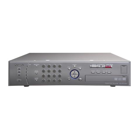
Panasonic

Panasonic WJMS424 - QUAD UNIT User manual

Panasonic WJMS488 - QUAD UNIT User manual

Panasonic

Panasonic WJMS488 - QUAD UNIT User manual

Panasonic WJ-FS616C User manual

Panasonic

Panasonic WJ-FS616C User manual
Panasonic WJMS424 - QUAD UNIT User manual
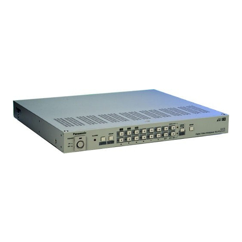
Panasonic

Panasonic WJMS424 - QUAD UNIT User manual

Panasonic WJMS424 - QUAD UNIT User manual

Panasonic

Panasonic WJMS424 - QUAD UNIT User manual

Panasonic WJMS424 - QUAD UNIT User manual

Panasonic

Panasonic WJMS424 - QUAD UNIT User manual

Panasonic KX-NCP Series User manual

Panasonic

Panasonic KX-NCP Series User manual

Panasonic WJ-FS309 User manual

Panasonic

Panasonic WJ-FS309 User manual

Panasonic WJFS616 - SWITCHER User manual

Panasonic

Panasonic WJFS616 - SWITCHER User manual

Panasonic WJ-FS28 User manual

Panasonic

Panasonic WJ-FS28 User manual

Panasonic WJ-FS309 User manual

Panasonic

Panasonic WJ-FS309 User manual

Panasonic WJ-FS109 User manual

Panasonic

Panasonic WJ-FS109 User manual

Panasonic WJFS316 - DIGITAL MULTIPLEXER User manual

Panasonic

Panasonic WJFS316 - DIGITAL MULTIPLEXER User manual

Panasonic WJFS216 - SWITCHER User manual

Panasonic

Panasonic WJFS216 - SWITCHER User manual

Panasonic WJ-FS616C User manual

Panasonic

Panasonic WJ-FS616C User manual
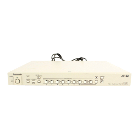
Popular Multiplexer manuals by other brands

Lynx P MX 3312 D Reference manual

Lynx

Lynx P MX 3312 D Reference manual

ShipModul MiniPlex-BT NMEA-0183 manual

ShipModul

ShipModul MiniPlex-BT NMEA-0183 manual

Transition Networks PSM-8E user guide

Transition Networks

Transition Networks PSM-8E user guide

Signametrics SMX4032 Operator's manual

Signametrics

Signametrics SMX4032 Operator's manual

Keithley 7711 user guide

Keithley

Keithley 7711 user guide

Pickering SIMRC 1050 Getting started

Pickering

Pickering SIMRC 1050 Getting started

Agilent Technologies E1346A Service manual

Agilent Technologies

Agilent Technologies E1346A Service manual

Simplex 2100 troubleshooting manual

Simplex

Simplex 2100 troubleshooting manual

System Q CCT290 instruction manual

System Q

System Q CCT290 instruction manual

Humandata LNX-205 user manual

Humandata

Humandata LNX-205 user manual

Patton electronics 1195/8E1 quick start guide

Patton electronics

Patton electronics 1195/8E1 quick start guide

Fiber Options S703V instruction manual

Fiber Options

Fiber Options S703V instruction manual

HP E1343A user manual

HP

HP E1343A user manual

RFL Communications SMX3 user manual

RFL Communications

RFL Communications SMX3 user manual

Equinox Systems MEGAPLEX Hardware reference manual

Equinox Systems

Equinox Systems MEGAPLEX Hardware reference manual

Pickering 40-614C user manual

Pickering

Pickering 40-614C user manual

Pickering 40-670C user manual

Pickering

Pickering 40-670C user manual

Raisecom RC802-60B Series user manual

Raisecom

Raisecom RC802-60B Series user manual

manuals.online logo
manuals.online logoBrands
  • About & Mission
  • Contact us
  • Privacy Policy
  • Terms and Conditions

Copyright 2025 Manuals.Online. All Rights Reserved.