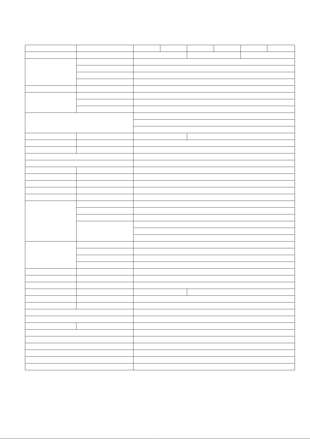
Panasonic NR-B32FX3 User manual

© 2013 Panasonic Co., Ltd. All rights reserved.
Unauthorized copying and distribution is a violation
of law.
Order Number PHARW1304002CE
Refrigerator-Freezer
Model No. NR-B32FX3
NR-B32FW3
NR-BG32FX3
NR-BG32FW3
Product Color W: White, X: Stainless
Destination E: Europe Continental, B: U.K. ,
G: Germany
TABLE OF CONTENTS
PAGE PAGE
1 Safety Precautions----------------------------------------------- 2
2 Specifications ----------------------------------------------------- 5
3 General/Introduction -------------------------------------------- 6
4Features------------------------------------------------------------- 7
5 Technical Descriptions ----------------------------------------13
6 Location of Controls and Components ------------------17
7 Installation Instructions ---------------------------------------19
8 Test Mode ----------------------------------------------------------23
9 Service Mode ----------------------------------------------------- 24
10 Troubleshooting Guide --------------------------------------- 27
11 Disassembly and Assembly Instructions--------------- 31
12 Maintenance ------------------------------------------------------ 48
13 Dimensions ------------------------------------------------------- 51
14 Schematic Diagram -------------------------------------------- 53
15 Exploded View and Replacement Parts List ----------- 54

2
1 Safety Precautions
The following are instructions that you must follow in order to prevent accidents during work, and to ensure the safety of the
repaired product.
Hazard and damages that may result from ignoring instructions are classified and explained, below.
The following labels describe the types of rules that need to be followed.
This section warns of the urgent danger of death or serious injury.
This section warns of the risk of death or serious injury.
This section warns of the risk of injury or damage to property.
This label shows a “reminder” action to be paid attention to.
This label shows a “prohibited” action.
This label shows a “compulsory” action to be followed without fail.
Be sure to discharge remaining refrigerant from the refrigeration unit.
Discharge refrigerant outdoors where there is no fire source.
Be sure to instruct the customer not to approach the place of discharge, and not to use fire.
Always use a pipe cutter for removing pipes.
If you use a welding machine, the refrigerant remaining in the pipe or compressor could catch fire and explode.
Pipes must be blown out with nitrogen before welding, to discharge any remaining refrigerant.
Always use the swage lock for sealing after filing with refrigerant.
If you use a welding machine, the refrigerant could catch fire and explode.
Ventilation close to the floor surface is required, as the refrigerant (R600) is heavier than air.
In particular, the basement must be adequately ventilated.
“Measurement/adjustment of refrigerant refill quantity” in a service must be performed outdoors where
there is no fire source.
Otherwise, you could run the risk of fire/explosion.
Use always a gas alarm.
If any refrigerant remains in work area, there will be a risk of fire/explosion.
Prohibited
Never use a naked flame in a place where any refrigerant might remain.
Prohibited
Do not leave the removed faulty compressor in doors.

3
Remove power plug
Before repair
Make sure to cut off the power line before disassembly, parts replacement and assembly.
Otherwise, electrical shock or injury may occur.
Electric shock hazard
Be careful of electrical shocks
Be careful of electric shock from live parts or electrical lead terminals when conducting voltage measurement and
other electrical servicing.
Voltage of the control board is approximately 280V when power is ON.
Do not touch live parts.
When replacing parts, do not touch live parts for at least 3 minutes after disconnecting the plug the power supply.
(A little time is required for electrical discharge of the condenser)
Use only fuses specified
When replacing fuses, use only specified in the circuit diagram. The use of nonspecific fuses may cause fire or
malfunction.
Punch the pipes of the faulty compressor securely.
Otherwise, the refrigerant remaining in the compressor oil might leak out during transporting and could catch fire
and explode.
Discharge refrigerant completely from the used service can for disposal in an outdoor place where there is no
fire source.
Otherwise, you could run the risk of fire/explosion.
Prohibited
Do not damage the refrigeration circuit (piping) of the refrigerator.
As the refrigerant is flammable, any damage could lead to fire/explosion.
If the refrigeration circuit is damaged, do not touch the refrigerator or use a naked flame. Open windows for
Ventilation.
As the refrigerant is flammable, any damage could lead to fire/explosion.
Disposal of a faulty compressor must be performed outdoors where there is no fire source.
The quantity of refrigerant in a service can carried in the vehicle must be the least possible, and below the
[regulation][regulated] limit. Keep the service can upright and below 40°C. (Quantity on board: 1.5kg or
below)
Use a designated part
Make sure to use a designated part when the part is marked( ) in circuit diagrams and parts lists.
Otherwise,smoke,fire or failure may occur.
Always conduct a safety inspection after completing service
And check the parts are reassembled correctly. Also confirm other fixings and wiring, for deterioration. Replace as
required. Always use a megohmmeter to measure the insulating resistance between both terminals of the power
plug and the earth terminal, and plug the power supply in after first confirming 1MΩor above.
When setting, check that the power cord or power plug is not jammed or pushed against the rear of the refrigera-
tor.
If the power cord or the power plug is damaged or loose, take appropriate measures such as replacing.
If the pins of the plug or the area the pins attach to are dirty, make sure they are cleaned thoroughly.

4
Install and remove glass shelving securely to prevent risk of injury
When moving, raise the adjustable legs
Dragging the refrigerator will damage the floor. For flooring that may become easily damaged put a protective
board in place.
Do not scrape the metal rails
High temperature hazard
Take care of very hot parts
The compressor, pipes etc. can be very hot during operation and directly after stopping. Also, the heater can be
very hot during power supply and immediately after power supply is stopped. Be careful not to burn yourself by
touching very hot parts.
High temperature hazard
Take care of very hot parts after welding
Pipes etc., are very hot after welding. Be careful not to burn yourself by touching very hot parts.
Take care when filling/discharging refrigerant
Liquid refrigerant directly touching the skin may cause frostbite.
Take care of burrs
Be careful not to cut yourself on metal or plastic burrs.
Take care of condenser/evaporator fins
Be careful not to injure yourself on the fin edges.

5
2 Specifications
*1: The amount of Ice Making Ability in 24 hours. Setting temperature, FC: 1°C, VC: 0°C, FC: -25°C.
*2: The Freezing Abilit in 24 hours. VC temperature is set to 1°C and in state of Super Freeze.
*3: Values of the Energy Consumption in year.
*4: This Measurement of Exterior Noise Emitted is measured by OFF condition of PC Fan Motor for Deodorizer.
Model NR-B32FX3 NR-B32FW3 NR-B32FX3 NR-B32FW3
NR-BG32FX3 NR-BG32FW3
Destination UK Europe except UK Germany
volume capacity
Total effective volume capacity
315L
Refrigerator compartment (PC)
179L
Vegetable compartment (VC) 46L
Freezer compartment (FC) 90L
External dimensions width/depth/height (mm) W601 ×D648 ×H1898
Internal dimensions
PC: width/depth/height (mm) W495 ×D478 ×H752.5
VC: width/depth/height (mm) W480 ×D334 ×H262
FC: width/depth/height (mm) W465 ×D267.5 ×H595
Installation size
Side: 20mm or above
Back: 50mm or above
Top: 100mm or above
Power supply plug Rating 250V/13A 250V/16A
Power supply cord Length 2.1m
Interior lamp (LED) Rating 1W
IEC protection against electric shock classes Class I
Climate Class SN-T
Refrigerator compartment sensor
Rating PCC:B=3808K±2%,R(0°C)=6.409kΩ
Freezer compartment sensor
Rating FCC:B=3850K±2%,R(-20°C)=18.9kΩ
Vegetable compartment sensor
Rating SCC:B=3808K±2%,R(-3°C)=7.490kΩ
Ambient compartment sensor
Rating ATC:B=3435K±2%,R(25°C)=10.0kΩ
Defrost temperature sensor
Rating DFC:B=3819K±2%,R(10°C)=3.899kΩ
Compressor
Type Full hermetic reciprocating system
Model ENI100E13DCH-C0EXS
Rotation speed 25/39/43/59/71(r/s)
Curled resistance cord
U-V: 5.79Ω±5%
U-W: 5.79Ω±5%
V-W: 5.79Ω±5%
Overlord relay
Model MM3-64BCX
Operation temperature without power
95 ± 5°C
Return temperature 61 ± 8°C
Operating current (A) 6.40A ± 7.5%
Fan motor Model/Rating U11P14BS1Z3/DC14V 0.19A
Electric baffle Model/Rating NSBD009ZA1/DC12V, 300p/s
VC heater Rating 230V/6914Ω/7.6W
Defrost heater Rating/Voltage
230-240V/330.6
Ω
/160-175W
220-230V/302.5Ω/160-175W
Thermal fuse Rating 250V/7A/70°C
Refrigerator oil Class/Fill S10/215 ± 5ml
Ice making ability*1 1.5kg/24h
Freezing ability*2 15.0kg/24h
Amp. Rating 1.15A
Values of the energy consumption*3 249kWh/y
Energy efficiency grade A++
Refrigerant charge R600a,70g
Measurement of exterior noise emitted*4 36db
Form polyurethane Cyclo pentane
Weight (Kg) 82kg

6
3 General/Introduction
3.1. Flow of Refrigerant And Air

7
4 Features
4.1. Features
4.1.1. High Efficiency Cabinet

8
4.1.2. Storage Solution

9
4.1.3. Refrigerator Compartment
4.1.4. Hygiene Active and Multi Airflow

10
4.1.5. Vegetable Case
4.1.6. Vitamin Safe

11
4.1.7. Hygiene Active

12
4.2. Functions
4.2.1. Features and functions
4.2.2. User alert functions
The following user alert functions are activated when a door has been left ajar for a prolonged period of time or when the tempera-
ture inside the refrigerator has risen.

13
5 Technical Descriptions
5.1. Temperature control for each compartment
5.1.1. FC temperature control
The compressor is turned on and off detecting the FCC temperature.
Operation: The setting temperature “-25°C” to “-17°C”, 9 levels change
Detection: FCC, ATC sensor
1. When power supply is turned on, FC temperature is displayed on the panel PCB by reading FC setting data of microcomputer
memories. The data is written in memory area of microcomputer, 5 seconds after FC setting change. After that, FC tempera-
ture is controlled by setting FC temperature of the panel PCB.
The FC setting data is memorized, though the power supply of this product is turned off. The setting temperature is fixed, after
the time to have set temperature change passed more than 5 seconds.
2. The setting temperature
The temperature, when it set on -21°C
The OFF/ON temperature value corresponding to each ATC temperature is as shown in the next graph.
5.1.2. PC temperature control
PC damper is controlled by the PCC temperature.
1. When power supply is turned on, PC temperature is displayed on the panel PCB by reading PC setting data of microcomputer
memories.
The data is written in memory area of microcomputer, 5 seconds after PC setting change. After that, PC temperature is con-
trolled by setting PC temperature of the panel PCB. The PC setting data is memorized though the power supply of this appli-
ance is turned off.

14
2. The setting temperature
The temperature, when it set on 4°C.
The OFF/ON temperature value corresponding to each ATC temperature is as shown in the next graph.
5.1.3. SC temperature control
The twin damper motor is turned on and off detecting the SCC temperature.
The temperature, when it set on 2°C.
The OFF/ON temperature value corresponding to each ATC temperature is as shown in the next graph.

15
5.2. Defrost Control
FC defrost period control corresponding to each ATC.
5.3. Photosynthesis-freshness-improving effect control
Input: The vitamin mode ON.
Output: LED of VC (Green LED, Blue LED)
5.4. FC Fan Control
5.5. Compressor Rotational Speed Control
For securing the amount of cooling according to the overload at a high ambient temperature, the rotational speed of the compressor
is changed by difference of temperature between FCC and FC Control setting, PCC and PC Control setting.
Detection : FCC, PCC, ATC sensor
5.5.1. The use rotational speed
• The rotational speed of compressor is changed by deference between FCC temperature standard value (ON temperature) and
FCC temperature, PCC temperature standard value (ON temperature) and PCC temperature.
The rotational speed according to ambient temperature is as follows, it doesn't drive in other rotational speeds.
• The use rotational speed
*Notes
In case of setting of “Super Freeze”, the rotational speed of “Super Freeze” take precedence.
5.6. Compressor starting control
The compressor is not start while waiting timer is operating.
And when power is turned on, compressor staring control is not available.
5.7. Demo Control
To promote in-store sales.
5.7.1. Start
Simultaneously open FC door and PC door and press "Up" and "Down" buttons for 10 seconds to start demo control.
However, demo control is not performed after initial defrosting.
Vitamin mode LED Operation
ON Blue LED Flashing
Green LED Flashing
OFF Blue LED Off
Green LED Off
ATC Compressor FC fan
12°CON ON
OFF OFF
13°C22°CON ON
OFF OFF
23°CON ON
OFF OFF
Setting rotational speed of compressor
Rotational speed R1 R2 R3 R4 R5
Setting value r/s 25 39 43 59 71
After power turning on 0 minute
After FC Defrost stopping (Improvement of start after defrost) 3 minutes
After compressor stopping (Prevention of trip when re-starting) 10 minutes
Sequence protection 10 minutes

16
5.7.2. Operation during Demo Control
1. Photodynamic silver L led control…door open, light ON
Optical vegetable control...general control (door open, light ON; door closed, light flashing)
2. Door operation…During demo control, if any button operation is not performed for 30 seconds, auto demo will be repeated.
If any button operation is performed, the same item as that of door operation is displayed.
During demo control, self-diagnosis is not displayed.
3. Load operation…Compressor stops
Defrosting heater stops
SC heater stops
Damper stops
4. Others
Temperature display…freezing chamber [-20], chilling chamber [4], temperature variable chamber [2]
Temperature rise alarm…none
Rotation speed display …6 pieces fixed
In case of power failure reset…demo mode will be stored and continued
5.7.3. Auto Demo Panel Display
After entering demo control, LEDs of display panel turn on or flash as shown in the following figure. (Auto demo)
In auto demo, operate SW to change to operation demo. In operation demo, return to auto demo if SW is not operated for 30 sec-
onds.

17
6 Location of Controls and Components
6.1. Display and Control Panel
Notes:
• Normally the panel displays are off. Displays appear when the buttons are operated, or the doors are opened.
• The displayed temperature may differ from the actual temperature.
• This refrigerator uses a microprocessor to control the temperature.
The temperature inside the refrigerator varies depending on such factors as changes in the room temperature, the speed at
which the compressor is operating, how frequently the doors are opened and closed, and how much food is stored inside and
how it is stored.

18
6.2. Components

19
7 Installation Instructions
7.1. Installation Instructions

20
This manual suits for next models
3
Table of contents
Other Panasonic Refrigerator-Freezer manuals

Panasonic
Panasonic NR-BD23AB1 User manual

Panasonic
Panasonic NR-AD20AB1 User manual

Panasonic
Panasonic NR-B32FX2 User manual

Panasonic
Panasonic NR-BN34EX2 User manual

Panasonic
Panasonic NR-BN31EX1 User manual

Panasonic
Panasonic NR-BN34AX1 User manual

Panasonic
Panasonic NR-B32FE2 User manual

Panasonic
Panasonic NR-B30FW1 User manual

Panasonic
Panasonic NR-BN31EW2 User manual

Panasonic
Panasonic NR-BN34FX1 User manual