Panasonic EY4541 User manual

Operating Instructions
Bedienungsanleitung
Instructions d’utilisation
Istruzioni per l’uso
Gebruiksaanwijzing
Manual de instrucciones
Brugsvejledning
Driftsföreskrifter
Bruksanvisning
Käyttöohjeet
Before operating this unit, please read these instructions completely and save this manual for future use.
Vor Inbetriebnahme des Gerätes die Betriebsanleitung bitte gründlich durchlesen und diese Broschüre zum späteren Nachschlagen
sorgfältig aufbewahren.
Lire entièrement les instructions suivantes avant de faire fonctionner l’appareil et conserver ce mode d’emploi à des fins de consultation
ultérieure.
Prima di usare questa unità, leggere completamente queste istruzioni e conservare il manuale per usi futuri.
Lees deze gebruiksaanwijzing aandachtig door voor u het apparaat in gebruik neemt en bewaar de gebruiksaanwijzing voor eventuele
naslag.
Antes de usar este aparato por primera vez, lea todas las instrucciones de este manual y guarde el manual para poderlo consultar en el
futuro.
Gennemlæs denne betjeningsvejledning før brugen og gem den til fremtidig brug.
Läs igenom hela bruksanvisningen innan verktyget tas i bruk. Spara bruksanvisningen för senare användning.
Før enheten tas i bruk, vennligst les disse alle anvisningene og oppbevar deretter bruksanvisningen for senere bruk.
Lue ohjeet huolella ennen laitteen käyttöönottoa ja säilytä tämä käyttöohje tallessa tulevaa tarvetta varten.
Cordless Jigsaw
Kabellose Stichsäge
Meule d'angle sans fil
Seghetto senza filo
Snoerloze decoupeerzaag
Sierra inalámbrica
Akku-dekupørsav
Sladdlös sticksåg
Oppladbar Stikksag
Ladattava pistosaha
Model No: EY4541

- 9 -
Original instructions: English
Translation of the original instructions:
Other languages
I. INTENDED USE
Thank you for purchasing the Pana-
sonic Jigsaw. This jigsaw can be used
with Panasonic rechargeable batteries
to provide excellent cutting perfor-
mance. The jigsaw is for cutting metal,
wood, and drywall only.
Read the “Safety Instructions” booklet
and the following before using.
II. ADDITIONAL
SAFETY RULES
1) Hold tool by insulated gripping
surfaces when performing an op-
eration where the cutting tool may
contact hidden wiring. Contact with
a “live” wire will also make exposed
metal parts of the tool “live” and
shock the operator.
2) Use clamps or another practical
way to secure and support the
workpiece to a stable platform.
Holding the work by hand or against
your body leaves it unstable and
may lead to loss of control.
3) Keep hands away from cutting
area and blade. Keep your insu-
lated gripping surfaces. If both
hands are holding the tool, they
cannot be cut by the blade.
4) Never hold piece being cut in
your hands or across your leg. It
is important to support the work
properly to minimize body exposure
or loss of control.
5) Be aware that this tool is always
in an operating condition, since it
does not have to be plugged into
an electrical outlet.
6) Always use safety goggles or
glasses with side shields. Ordi-
nary eye or sun glasses are NOT
safety glasses.
7) When this tool is used for
woodworking in confined areas
(e.g. indoors), wear dust mask.
8) Avoid cutting nails. Inspect work-
piece for any nails and remove
them before operation.
9) Do not cut oversized workpiece.
10) Check for the proper clearance
beyond the workpiece before cut-
ting so that the blade will not
strike the floor, workbench, etc.
11) Hold the tool firmly.
12) Make sure the blade is not con-
tacting the workpiece before the
switch is turned on.
13) Keep hands away from moving
parts.
14) Do not touch the blade or work-
piece immediately after opera-
tion; they may be extremely hot
and could burn your skin.
15) Never swing tool.
16) Do not use blades which are de-
formed or cracked.
17) Do not use blades which do not
comply with the characteristics
specified in these instructions.
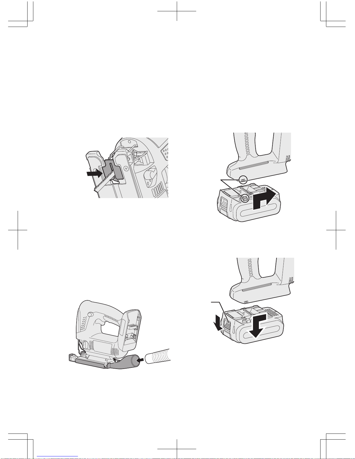
18) Remove the battery pack from the
tool body before replacement of
the blade, making adjustments,
or other maintenance work.
19) Wear ear protectors when using
the tool for extended periods.

- 10 -
Symbol Meaning
V Volts
Direct current
n0No load speed
…min
-1
Revolutions or reciproca-
tions per minutes
Ah Electrical capacity of
battery pack
To reduce the risk of
injury, user must read
and understand instruc-
tion manual.
For indoor use only.
WARNING:
• Do not use other than the Pana-
sonic battery packs that are de-
signed for use with this rechargea-
ble tool.
• Panasonic is not responsible for
any damage or accident caused
by the use of the recycled battery
pack and the counterfeit battery
pack.
• Do not dispose of the battery pack
in a fire, or expose it to excessive
heat.
• Do not drive the likes of nails into
the battery pack, subject it to
shocks, dismantle it, or attempt to
modif
y
it.
• Do not allow metal objects to
touch the batter
y
pack terminals.
• Do not carry or store the battery
pack in the same container as
nails or similar metal ob
j
ects.
• Do not charge the battery pack in
a high-temperature location, such
as next to a fire or in direct sun-
light. Otherwise, the battery may
overheat, catch fire, or explode.
• Never use other than the dedi-
cated charger to charge the bat-
tery pack. Otherwise, the battery
ma
y
leak, overheat, or explode.
• After removing the battery pack
from the tool or the charger, always
reattach the pack cover. Otherwise,
the batter
y
contacts could be
shorted, leadin
g
to a risk of fire.
• When the Battery Pack Has Dete-
riorated, Replace It with a New
One. Continued use of a dam-
aged battery pack may result in
heat generation, ignition or bat-
tery rupture.
III. ASSEMBLY
WARNING:
To reduce the risk of injury, always
remove battery pack before changing
the blade.
Inspection before use
• Has the correct jigsaw blade been
attached for the object to be cut?
• Has the correct stem shape and
thickness of the blade been
mounted?
• Check if the blade is fixed securely?
• Check if the blade is cracked or broken.
• Check that there are no foreign objects
in the object to be cut.
Installing and removing the blade
Installation
1. Wipe away any cutting dust from the
blade and the blade clamp bracket.
2. Lift up the blade Attach/Remove lever.

- 11 -
3. Insert the blade into the blade
clamp bracket and set the back of
the blade along the roller guide so
that the back of the jigsaw blade
slides along the roller guide.
4. Release the blade Attach/Remove
lever.
• When the blade is secured in place
then lever will return to its original po-
sition.
• Check that the back of blade is setting
in the groove in the roller guide.
WARNING:
If you do not insert the saw blade
deep enough, the saw blade may be
ejected unexpectedly during opera-
tion. This can be extremely danger-
ous.
Removal
1. Lift up the blade Attach/Remove lever.
2. Pull out the blade.
Adjusting the base
1. Use the hex wrench to loosen the
base fixing screw.
2. Move the base along the base ad-
justment hole to set its position. (See
the diagram at right.)
• The base can be adjusted to between
0° and 45° sideways and the for-
ward/back position can also be ad-
justed. If tilting the base sideways,
remove the dust cover first.
• Refer to the bevel index to determine
the angle.
• Rip fence fixing screw should be lo-
cated on the opposite side tool is be-
veled.
3. Use the hex wrench to tighten the
base fixing screw.
Roller guide

- 12 -
Position of base and purpose of use
Base adjustment
hole position Purpose of use
Normal right-angled
cutting
Cutting at an angle
between 0° and 45°
Cutting at an angle of
45°
Cutting close to the end
of a wall
NOTE:
This is only a rough guide. The ac-
tual angle of the cut will be affected
by factors such as the way the tool
is held against the surface.
Adjusting the orbital stroke mode
• Adjust the orbital stroke mode to the
object to be cut.
321
0
Lever
position Blade
movement Main
applications
0
Vertical only
•Cutting hard met-
als such as steel
•Smooth cutting of
building materials
and plywood
boards
•Cutting around
small curves
1
Low orbital stroke
mode
•Cutting softer
metals such as
aluminum and
other non-ferrous
metals
•Cutting hardwood,
plywood boards
and plastics
2
Medium orbital
stroke mode
•Cutting fairly soft
materials
•Cutting wood and
composite boards
•High-speed cut-
ting of aluminum
and soft steel
3
High orbital
stroke mode
•Cutting soft mate-
rials
•High-speed cut-
ting of materials
such as wood,
composite boards
and plastics
• If you would like to produce a cleaner
finish, set the orbital stroke mode to
a lower level.
321
0

- 13 -
Anti-splintering plate
Use the anti-splintering plate to reducing
splinter while cutting wood.
Installation
1. Set the base at 90 degree position.
2. Place the anti-splintering plate on the
underside of the base, and gently
push it to be installed.
• Install so that the beveled edge of the
slot in the middle of the anti-splintering
plate is facing toward the jigsaw.
Dust adapter for vacuum cleaner
(
EY9X009
) (Available as an ac-
cessory, not included)
You can use a vacuum cleaner to
collect cutting dust while cutting.
Installation
1. Attach the hook of the dust collection
adapter to the front of the base.
2. Snap the rear to install it.
3. Attach the hose of the vacuum cleaner.
• It is recommended to use a dust adapter
for reducing the risk of damaging the
surface of the object being cut.
Attaching or Removing Battery
Pack
1. To connect the battery pack:
Line up the alignment marks and attach
the battery pack.
• Slide the battery pack until it locks
into position.
2. To remove the battery pack:
Pull the button from the front to re-
lease the battery pack.
Button
A
lignment
marks

- 14 -
IV. OPERATION
1. Push the switch lock lever down, pull
the power switch.
• The speed increases with the amount
of depression of the power switch.
2. Once cutting is finished, release the
power switch.
3. Check that the temperature of the
blade has dropped sufficiently, and
then remove the blade.
CAUTION:
When operating the tool by pulling the
trigger, there may be a momentary lag
before rotation starts. This does not
signal a malfunction.
• This lag occurs as the tool’s circuitry
starts up when the trigger is pulled for
the first time after installing a new bat-
tery pack or after the tool has not been
used for at least 1 minute (or at least 5
minutes when the LED is on). Rotation
will start without any lag during second
and subsequent operations.
Cutting
NOTE:
• Check that there are no obstacles to
cut underneath workpiece.
• Check that there are no objects such
as nails in the material to be cut.
If the blade comes into contact with any
such objects during cutting, a strong
reaction force will be generated and
severe injury may occur.
• Do not place your hand on the object
in the direction cutting is to take place.
If this is not observed, there is a risk
of injury.
• Do not touch the jigsaw blade im-
mediately after cutting.
If this is not observed, burns may occur.
Cutting along marked lines
1. Place the object to be cut onto the
base, and align the blade with the
marked line.
• Do not touch the blade against the
object to be cut before pulling the
power switch.
2. Pull the power switch, wait until the
speed has stabilized, and then place
the base against the object to be cut
and cut along the marked lines.

- 15 -
• When cutting complex shapes such
as shapes with many small curves,
reduce the cutting speed and the
turning speed.
Plunge cutting
1. Make a drill hole in the section to be
plunge cut in order to let the blade
pass through.
2. Insert the blade into a hole without
touching the workpiece, and then
turn on the power switch.
3. Cut along the marked line.
Using a rip fence (EY9X011E)
(Available as an accessory,
not included)
A rip fence can be used for cutting
parallel lines and for cutting circles
and arcs.
Installing the rip fence
1. Loosen the rip fence fixing screw.
2.
Pass the rip fence through the mount.
3. Adjust the cutting position and then
tighten the fixing screw.
Cutting at the same width
1. Place the base onto the workpiece
so that the edge of the rip fence
and workpiece are put together.
2. Without letting the blade touch the
workpiece, turn on the power switch.
3. Face the rip fence firmly to the
workpiece to cut parallel line.

- 16 -
Cutting circles
1. If cutting away a section, make a
drill hole on workpiece to let the
jigsaw blade pass through.
2. Align the pin hole of the rip fence
with the center of the circle, and
then use a nail or screw to hold the
object in place.
3. Without touching the workpiece,
turn on the power switch.
4. Cut along the marked line.
Control Panel
(1) (3)
(2)
(1) LED light
Before the use of LED
light, always pull the
power switch once.
Press the LED
light button.
The light illuminates
with very low current,
and it does not ad-
versely affect the
performance of the
driver during use or
its battery capacity.
CAUTION:
• The built-in LED light is designed to
illuminate the small work area tem-
porarily.
• Do not use it as a substitute for a
regular flashlight, since it does not
have enough brightness.
• LED light turns off when the tool has
not been used for 5 minutes.
Caution : DO NOT STARE INTO BEAM.
Use of controls or adjustments or performance
of procedures other than those specified
herein may result in hazardous radiation ex-
posure.
(2) Overheat warning lamp
To protect the motor or battery, be
sure to note the following when car-
rying out this operation.
• If the motor or battery becomes hot, the
protection function will be activated and
the motor or battery will stop operating.
The overheat warning lamp on the
control panel illuminates or flashes
when this feature is active.
• If the overheating protection feature
activates, allow the tool to cool tho-
roughly (at least 30 minutes). The tool
is ready for use when the overheat
warning lamp goes out.
• Avoid using the tool in a way that
causes the overheating protection fea-
ture to activate repeatedly.
• If the tool is operated continuously under
high-load conditions or if it is used in
hot-temperature conditions (such as
during summer), the overheating protec-
tion feature may activate frequently.
Off
(normal
operation)
Flashing: Overheat
Indicates operation has
been halted due to
battery overheating.

- 17 -
• If the tool is used in cold-temperature
conditions (such as during winter) or if
it is frequently stopped during use, the
overheating protection feature may not
activate.
• The performance of the EY9L42 dete-
riorates significantly at and below
10°C due to work conditions and other
factors.
• The ambient temperature range is be-
tween 0°C (32°F) and 40°C (104°F).
If the battery pack is used when the bat-
tery temperature is below 0°C (32°F), the
tool may fail to function properly.
• When charging a cool battery pack
(below 0°C (32°F)) in a warm place,
leave the battery pack at the place and
wait for more than one hour to warm up
the battery to the level of the ambient
temperature.
(3) Battery low warning lamp
Excessive (complete) discharging of
lithium ion batteries shortens their
service life dramatically. The tool in-
cludes a battery protection feature
designed to prevent excessive dis-
charging of the battery pack.
• The battery protection feature acti-
vates immediately before the battery
loses its charge, causing the battery
low warning lamp to flash.
• If you notice the battery low warning
lamp flashing, charge the battery
pack immediately.
• If it is started with too little battery
power remaining, the tool may stop
operating without the battery low
warning lamp flashing first. This in-
dicates that there is too little battery
power remaining to use the tool, and
the battery pack should be charged
before further use.
• If the tool is subject to a sudden load
during use that causes the motor to
lock up, the overdischarge preven-
tion sensor may be triggered, and
the battery low warning lamp may
flash. The lamp will stop flashing
once you address the cause of the
motor’s locking up and cycle the
trigger.
Off
(normal
operation)
Flashing
(No charge)
Battery protection
feature active

- 18 -
[Battery Pack]
For Appropriate Use of
Battery pack
Li-ion Battery pack
• For optimum battery life, store the
Li-ion battery pack following use
without charging it.
• When charging the battery pack, con-
firm that the terminals on the battery
charger are free of foreign substances
such as dust and water etc. Clean the
terminals before charging the battery
pack if any foreign substances are
found on the terminals.
The life of the battery pack terminals
may be affected by foreign sub-
stances such as dust and water etc.
during operation.
• When battery pack is not in use, keep
it away from other metal objects like:
paper clips, coins, keys, nails, screws,
or other small metal objects that can
make a connection from one terminal
to another.
Shorting the battery terminals together
may cause sparks, burns or a fire.
• When operating the battery pack,
make sure the work place is well ven-
tilated.
• When the battery pack is removed
from the main body of the tool, re-
place the battery pack cover imme-
diately in order to prevent dust or dirt
from contaminating the battery ter-
minals and causing a short circuit.
Battery Pack Life
The rechargeable batteries have a li-
mited life. If the operation time be-
comes extremely short after recharg-
ing, replace the battery pack with a
new one.
Battery Recycling
ATTENTION:
For environmental protection and
recycling of materials, be sure that
it is disposed of at an officially as-
signed location, if there is one in
your country.
[Battery Charger]
Charging
Cautions
• If the temperature of the battery pack
falls approximately below −10°C
(14°F), charging will automatically
stop to prevent degradation of the
battery.
• The ambient temperature range is
between 0°C (32°F) and 40°C (104°F).
If the battery pack is used when the
battery temperature is below 0°C (32°F),
the tool may fail to function properly.
• When charging a cool battery pack
(below 0°C (32°F)) in a warm place,
leave the battery pack at the place
and wait for more than one hour to
warm up the battery to the level of the
ambient temperature.
• Cool down the charger when charg-
ing more than two battery packs
consecutively.
• Do not insert your fingers into contact
hole, when holding charger or any
other occasions.
To prevent the risk of fire or dam-
age to the battery charger.
• Do not use power source from an
engine generator.
• Do not cover vent holes on the
charger and the battery pack.
• Unplug the charger when not in use.

- 19 -
Li-ion Battery Pack
NOTE:
Your battery pack is not fully charged
at the time of purchase. Be sure to
charge the battery before use.
Battery charger
1. Plug the charger into the AC outlet.
2. Insert the battery pack firmly into the
charger.
1.Line up the alignment marks and
place the battery onto the dock on
the charger.
2.Slide forward in the direction of the
arrow.
3. During charging, the charging lamp
will be lit.
When charging is completed, an in-
ternal electronic switch will auto-
matically be triggered to prevent
overcharging.
• Charging will not start if the battery
pack is warm (for example, imme-
diately after heavy-duty operation).
The orange standby lamp will be
flashing until the battery cools down.
Charging will then begin automati-
cally.
4. The charge lamp (green) will flash
slowly once the battery is approx-
imately 80% charged.
5 When charging is completed, the
charging lamp in green color will
turn off.
6. If the temperature of the battery pack
is 0°C or less, charging takes longer
to fully charge the battery pack than
the standard charging time.
Even when the battery is fully charged,
it will have approximately 50% of the
power of a fully charged battery at
normal operating temperature.
7.
Consult an authorized dealer if the
charging lamp (green) does not turn
off
.
8. If a fully charged battery pack is
inserted into the charger again, the
charging lamp lights up. After sev-
eral minutes, the charging lamp in
green color will turn off.
9. Remove the battery pack while the
battery pack release button is held
up.
A
lignment marks
Battery pack
release button

- 20 -
LAMP INDICATIONS
Charging is completed. (Full charge.)
Battery is approximately 80% charged.
Now charging.
Charger is plugged into the AC outlet. Ready to charge.
Charging Status Lamp.
Left: green Right: orange will be displayed.
Battery pack is cool.
The battery pack is being charged slowly to reduce the load on the battery.
Battery pack is warm.
Charging will begin when temperature of battery pack drops. If the temperature of the
battery pack is -10° or less, the charging status lamp (orange) will also start flashing .
Charging will begin when the temperature of the battery pack goes up"
Charging is not possible. Clogged with dust or malfunction of the bat-
tery pack.
Turn off Lit Flashing
(Green) (Orange)
Information for Users on Collection and Disposal of Old
Equipment and used Batteries
These symbols on the products, packaging, and/or accompanying
documents mean that used electrical and electronic products and
batteries should not be mixed with general household waste.
For proper treatment, recovery and recycling of old products and used
batteries, please take them to applicable collection points, in accordance
with your national legislation and the Directives 2002/96/EC and
2006/66/EC.
By disposing of these products and batteries correctly, you will help to
save valuable resources and prevent any potential negative effects on
human health and the environment which could otherwise arise from
inappropriate waste handling.
For more information about collection and recycling of old products and
batteries, please contact your local municipality, your waste disposal
service or the point of sale where you purchased the items.
Penalties may be applicable for incorrect disposal of this waste, in
accordance with national legislation.
For business users in the European Union
If you wish to discard electrical and electronic equipment, please contact your
dealer or supplier for further information.

- 21 -
[Information on Disposal in other Countries outside the Euro-
pean Union]
These symbols are only valid in the European Union. If you wish to discard these
items, please contact your local authorities or dealer and ask for the correct method
of disposal.
Note for the battery symbol (bottom two symbol examples):
This symbol might be used in combination with a chemical symbol. In this case it
complies with the requirement set by the Directive for the chemical involved.
V. MAINTENANCE
• Use only a dry, soft cloth for wiping the unit. Do not use a damp cloth, thinner,
benzine, or other volatile solvents for cleaning.
• In the event that the inside of the tool or battery pack is exposed to water, drain
and allow to dry as soon as possible. Carefully remove any dust or iron filings that
collect inside the tool. If you experience any problems operating the tool, consult
with a repair shop.
VI. ACCESSORIES
CAUTION:
• The use of any accessories not specified in this manual may result in fire,
electric shock, or personal injury. Use recommended accessories only.
Metal Blade
•EY9SXMJ0E
For cutting metal in general
Wood Blade
•EY9SXWJ0E
For cutting wood in general
Drywall Blade
•EY9SXXJ0E
For cutting drywall in general
Rip Fence (Optional accessory)
•EY9X011E
For convenience of rip cuts and repeated
cut of same width.
Dust Adaptor for Vacuum Cleaner
(Optional accessory)
•EY9X009

- 22 -
VII. SPECIFICATIONS
MAIN UNIT
Model EY4541
Motor 14.4 V DC
Max thickness of mounting blade 1.3 mm
Length of strokes 20 mm
Strokes per minute 0 - 2400 /min
Maximum cutting
capacities
Wood 65 mm
Mild steel 6 mm
Aluminum 10 mm
Overall length 270 mm
Weight (with battery pack) 2.25 kg
Noise, Vibration See the included sheet
BATTERY PACK
Model EY9L41 EY9L42 EY9L44 EY9L45
Storage battery Li-ion Battery
Battery voltage 14.4 V DC (3.6 V x 4 cells) 14.4 V DC (3.6 V x 8 cells)
BATTERY CHARGER
Model EY0L81
Electrical rating See the rating plate on the bottom of the charger
Weight 0.93 kg
Charging time
EY9L41 EY9L42 EY9L44 EY9L45
Usable: 45 min Usable: 30 min Usable: 50 min Usable: 65 min
Full: 60 min Full: 35 min Full: 65 min Full: 80 min
Model EY0L82
Electrical rating See the rating plate on the bottom of the charger
Weight 0.93 kg
Charging time
EY9L41 EY9L42 EY9L44 EY9L45
Usable: 35 min Usable: 30 min Usable: 40 min Usable: 50 min
Full: 50 min Full: 35 min Full: 55 min Full: 60 min
NOTE: This chart may include models that are not available in your area.
Please refer to the latest general catalogue.
NOTE: For the dealer name and address, please see the included warranty card.

- 23 -
VIII. ELECTRICAL
PLUG INFOR-
MATION
FOR YOUR SAFETY PLEASE READ
THE FOLLOWING TEXT CAREFULLY
This appliance is supplied with a moulded
three pin mains plug for your safety and
convenience.
A 5 amp fuse is fitted in this plug.
Should the fuse need to be replaced please
ensure that the replacement fuse has a rat-
ing of 5 amp and that it is approved by ASTA
or BSI to BS1362.
Check for the ASTA mark or the BSI mark
on the body of the fuse.
If the plug contains a removable fuse cover
you must ensure that it is refitted when the
fuse is replaced.
If you lose the fuse cover the plug must not
be used until a replacement cover is ob-
tained.
A replacement fuse cover can be purchased
from your local Panasonic Dealer.
IF THE FITTED MOULDED PLUG IS UN-
SUITABLE FOR THE SOCKET OUTLET IN
YOUR HOME THEN THE FUSE SHOULD
BE REMOVED AND THE PLUG CUT OFF
AND DISPOSED OF SAFELY.
THERE IS A DANGER OF SEVERE
ELECTRICAL SHOCK IF THE CUT OFF
PLUG IS INSERTED INTO ANY 13 AMP
SOCKET.
If a new plug is to be fitted please observe
the wiring code as shown below.
If in any doubt please consult a qualified
electrician.
IMPORTANT:
The wires in this mains lead are
coloured in accordance with the
following code:
Blue: Neutral
Brown: Live
As the colours of the wire in the mains lead
of this appliance may not correspond with
the coloured markings identifying the termi-
nals in your plug, proceed as follows.
The wire which is coloured BLUE must be
connected to the terminal in the plug which
is marked with the letter N or coloured
BLACK.
The wire which is coloured BROWN must be
connected to the terminal in the plug which is
marked with the letter L or coloured RED.
Under no circumstances should either of
these wires be connected to the earth ter-
minal of the three pin plug, marked with the
letter E or the Earth Symbol .
How to replace the fuse: Open the fuse
compartment with a screwdriver and re-
place the fuse and fuse cover if it is re-
movable.
This apparatus was produced to BS800.
ONLY FOR U. K.
Fuse Cover
Other manuals for EY4541
4
Table of contents
Other Panasonic Saw manuals

Panasonic
Panasonic EY3503 User manual

Panasonic
Panasonic EY3531 - 15.6V WOOD SAW User manual

Panasonic
Panasonic EY47A1 User manual

Panasonic
Panasonic EY3544-U1 User manual

Panasonic
Panasonic EY45A5 User manual

Panasonic
Panasonic EY3551 User manual

Panasonic
Panasonic EY45A5 User manual

Panasonic
Panasonic EY3551 - 18V WOOD SAW User manual

Panasonic
Panasonic EY45A1 User manual