manuals.online logo
Brands
  1. Home
  2. •
  3. Brands
  4. •
  5. Panasonic
  6. •
  7. Security Camera
  8. •
  9. Panasonic WV-SPW311AL User manual

Panasonic WV-SPW311AL User manual

Included Installation Instructions
PGQX1992XA sL0915-2115 Printed in China
IMPORTANT:
●Also waterproof the 2P power cable (F: accessory),
4P alarm cable (E: accessory), and external connec-
tions in the same way.
●Stretch the tape to approx. twice its length (see the
illustration) and wind it around the cable. Insufficient
tape stretch causes insufficient waterproofing.
●To prevent the Ethernet cable hook from coming
loose easily, fit the LAN connector cover (D: acces-
sory) onto the pigtail cable as illustrated, and then
slide it in the direction indicated by the arrow. The
connector of the Ethernet cable used with this cam-
era must meet the following restrictions.
Height when inserted (From bottom to hook.):
Max. 16 mm {5/8 inches}
Connector width: Max. 14 mm {9/16 inches}
●To install this product outdoors, be sure to waterproof
the cables.
Waterproof grade (IEC IP66 or equivalent) is applied
to this product only when it is installed correctly as
described in these operating instructions and appro-
priate waterproof treatment is applied.
The camera mount bracket and camera arm are not
waterproof.
Installation Guide
Network Camera
Model No.
WV-SPW531AL / WV-SPW311AL
● This manual describes the installation procedures, network camera installation, cable
connections, and eld-of-view adjustment.
● Before reading this manual, be sure to read the Important Information.
● This manual describes how to install the network camera using model WV-SPW531AL
as an example.
Parts and functions
The component names of the camera are as follows. Refer to the illustration when
installing or adjusting the camera.
Standard accessories Making connections
Important Information ............................... 1 pc.
Warranty card ........................................... 1 set
Code label*2 .............................................. 1 pc.
Installation Guide (this document)............ 1 set
CD-ROM*1................................................. 1 pc.
*1
The CD-ROM contains the operating instructions and different kinds of tool software programs.
*2 This label may be required for network management. The network administrator shall retain
the code label.
ACamera mount bracket cover ........... 2 pcs.
BCamera mount bracket cover fixing screw
(M3 × 6 mm {1/4 inches}) ................... 3 pcs.
(of them, 1 for spare)
CWaterproof tape .................................. 1 pc.
DLAN connector cover ........................... 1 pc.
E4P alarm cable .................................... 1 pc.
F2P power cable .................................... 1 pc.
GSafety wire ........................................... 1 pc.
HWire lug fixing screw
M3 × 10 mm {3/8 inches} ................... 2 pcs.
(of them, 1 for spare)
ISafety wire lug ..................................... 1 pc.
JAuxiliary handle.................................... 1 pc.
Turn off each system’s power supply before making a connection. Before making connections,
prepare the required peripheral devices and cables.
IMPORTANT:
●Use all 4 pairs (8 pins) of the Ethernet cable (category 5e or better, straight).
●The maximum cable length is 100 m {328 feet}.
●Make sure that the PoE device in use is compliant with IEEE802.3af standard.
●When connecting both the 12 V DC power supply and the PoE device for power sup-
ply, 12 V DC will be used for power supply*.
*If a 12 V DC power supply and a PoE hub or router are used at the same time, net-
work connections may not be possible. In this case, disable the PoE settings. Refer
to the operating instructions of the PoE hub or router in use.
*Depending on the PoE device used, if you stop the 12 V DC power supply after
operating it and a PoE hub or router at the same time, the power supply may stop,
causing the camera to restart.
●When the Ethernet cable is disconnected once, reconnect the cable after around 2
seconds. When the cable is quickly reconnected, the power may not be supplied
from the PoE device.
●When cables are used outdoors, there is a chance that they may be affected by light-
ning. In this case, install a lightning arrester just before where the Ethernet cable
connects to the camera.
Connect an Ethernet cable (category 5e or better, straight)
Waterproof treatment for the cable joint sections
When connecting to a network using a PoE hub
Microphone/line input cable
Connect a stereo mini plug (ø3.5 mm {1/8 inches}).
● Input impedance: Approx. 2 kΩ (unbalanced)
●Recommended cable length: Less than 1 m {3.28 feet} (for microphone input) Less than
10 m {32.8 feet} (for line input)
●Recommended microphone: Plug-in power type (option)
• Supply voltage: 2.5 V ±0.5 V
• Recommended sensitivity of microphone: -48 dB ±3 dB (0 dB=1 V/Pa,1 kHz)
●Input level for line input: Approx. -10 dBV
Connect an external amplifier-embedded speaker to the audio/
monitor output cable
Connect a stereo mini plug (ø3.5 mm {1/8 inches}).
● Output impedance: Approx. 600 Ω (unbalanced)
●Recommended cable length: Less than 10 m {32.8 feet}
●Output level: -20 dBV (can switch to monitor output)
IMPORTANT:
●Connect/disconnect the audio cables and turn on the power of the camera after turn-
ing off the power of the audio output devices. Otherwise, loud noise may be heard
from the speaker.
●Make sure that the stereo mini plug is connected to this cable. When a monaural mini
plug is connected, audio may not be heard. When connecting a monaural speaker
with amplifier, use a locally procured conversion cable (mono-stereo).
Adequate waterproof treatment is required for the cables when installing the camera with cables
exposed or installing it under the eaves.
The camera body is waterproof, but the cable ends are not waterproof. Be sure to use the sup-
plied waterproof tape at the points where the cables are connected to apply waterproof treatment
in the following procedure.
Failure to observe this or use of a tape other than the provided waterproof tape (such as a vinyl
tape) may cause water leakage resulting in malfunction.
Before starting the installation, check the entire system conguration.
The following illustration gives a wiring example of how to connect the camera to the network via
a PoE device (hub).
<Ethernet cable> <Alarm input/output cable, power cable, micro-
phone/line input cable, audio/monitor output
cable>
Stretch the tape to
approx. twice its length.
2×
IMPORTANT:
● The adjustment monitor is used to adjust the field of view when installing or servicing
the camera. It is not provided for recording/monitoring use.
● Depending on the adjustment monitor, some characters (camera title, preset ID, etc.)
may not be displayed on the screen.
●Use a switching hub or a router which is compliant with 10BASE-T/100BASE-TX.
●If a PoE hub is not used, each network camera must be connected to a 12 V DC
power supply.
●When using 12 V DC, power supply from a PoE hub or router is not required.
The hook engages
with the connector
terminal
LAN connector cover
(D: accessory)
*1 SDXC/SDHC/SD memory card is described as SD memory card.
*2 Depending on the scanning application used, the Data Matrix may not be
able to be read correctly. In this case, access the site by directly entering the
following URL.
http://security.panasonic.com/pss/security/support/qr_sp_select.html
Connect the power cable
IMPORTANT:
●Use 12 V DC power supply that is insulated from the commercial AC power.
●Be sure to use the 2P power cable (F: accessory) provided with this product.
●Be sure to fully insert the 2P power cable (F: accessory) into the 12 V DC power
supply terminal. Otherwise, it may damage the camera or cause malfunction.
●When installing the camera, make sure that excessive force is not applied to the
power cable.
●Be sure to use an AC adaptor compliant with the specifications (written in the indication
label on the side of this unit) regarding power source and power consumption.
Power cable
12 V DC
Red Positive
Black Negative
<Required cable>
Ethernet cable (category 5e or better, straight)
Use an Ethernet cable (category 5e or better, cross) when directly connecting the camera to a PC.
Note:
●Off, input, and output of the external I/O terminal 2 and 3 can be switched by configur-
ing the setting. Refer to the Operating Instructions on the provided CD-ROM for further
information about the external I/O terminal 2 and 3 (ALARM IN2, 3) settings (“Off”,
“Alarm input”, “Alarm output” or “AUX output”).
IMPORTANT:
●Be sure to use the 4P alarm cable (E: accessory) provided with this product.
●Install external devices so that they do not exceed the ratings above.
●When using the external I/O terminals as the output terminals, ensure they do not
cause signal collision with external signals.
Connect the alarm input/output cable
<Ratings>
● ALARM IN1 (DAY/NIGHT IN, Auto time adjustment), ALARM IN2, ALARM IN3
Input specification: No-voltage make contact input (4 V - 5 V DC, internally pulled up)
OFF: Open or 4 V - 5 V DC
ON: Make contact with GND (required drive current: 1 mA or more)
●ALARM OUT, AUX OUT
Output specification: Open collector output (maximum applied voltage: 20 V DC)
Open: 4 V - 5 V DC by internal pull-up
Close: Output voltage 1 V DC or less (maximum drive current: 50 mA)
* The default of EXT I/O terminals is “Off”.
4P alarm cable (E: accessory)
PoE device (hub)
PC
Adjustment monitor
Ethernet cable
(category 5e or better, straight)
Microphone
Powered
speaker
Analog monitor
PC
For U.S. and Canada:
Panasonic System Communications
Company of North America,
Unit of Panasonic Corporation
of North America
www.panasonic.com/business/
For customer support, call 1.800.528.6747
Two Riverfront Plaza, Newark, NJ 07102-5490
Panasonic Canada Inc.
5770 Ambler Drive, Mississauga,
Ontario, L4W 2T3 Canada
(905)624-5010
www.panasonic.ca
For Europe and other countries:
Panasonic Corporation
http://www.panasonic.com
Panasonic System Networks Co., Ltd.
Fukuoka, Japan
Authorised Representative in EU:
Panasonic Testing Centre
Panasonic Marketing Europe GmbH
Winsbergring 15, 22525 Hamburg, Germany
The following parts are used during installation procedures.
GND (black)
ALARM IN3, AUX OUT (gray)
(Alarm input 3, AUX output)
ALARM IN2, ALARM OUT (red) (Alarm input 2, Alarm output)
ALARM IN1, DAY/NIGHT IN, Auto time adjustment (green) (Alarm input 1/ DAY/
NIGHT switching input/ Auto time adjustment)
RJ45 (female)
Network cable
Ethernet cable
(category 5e or better, straight)
4P alarm cable
(E: accessory)
Alarm input/output cable
(External I/O terminal)
Power cable
(12 V DC) 2P power cable
(F: accessory)
Microphone/line input cable (white)
Audio/monitor output cable (black)
Caution:
●A READILY ACCESSIBLE DISCONNECT DEVICE SHALL
BE INCORPORATED TO THE EQUIPMENT POWERED
BY 12 V DC POWER SUPPLY.
●ONLY CONNECT 12 V DC CLASS 2 POWER SUPPLY (UL
1310/CSA 223) or LIMITED POWER SOURCE (IEC/EN/
UL/CSA 60950-1).
Wind the tape in a
half-overlapping manner. Wind the tape in a
half-overlapping
manner.
© Panasonic System Networks Co., Ltd. 2015
12 V DC
(red)
GND
(black)
Waterproof tape (
C
: accessory)
Waterproof tape (
C
: accessory)
Connect the output cable of the AC adaptor to the 2P power cable (
F
:accessory).
WV-SPW531AL
Sunshield
TILT lock screw
Camera
arm
Front cover
YAW
lock screw
PAN lock screw
WV-Q120A
(option)
Camera mount bracket
covers (2 pcs.)
(A: accessory)
Safety wire
(G: accessory)
Camera
mount bracket
Side B (Upper)
Side A (lower)
Name plate
Dehumidifying device
IR LED
Zoom knob
TELE
WIDE
Auto focus (AF)
button
Two-dimensional
matrix barcode
(Data Matrix):
To our website*2
●When the camera is able to communicate with the Lights orange
connected device
LINK indicator
●When data is being sent via the network camera Blinks green (accessing)
ACT indicator
●When AF (Auto Focus) operation is being executed
Blinks red (about once per second)
●When the camera is being started Lights red
●When an SD memory card
*1
is recognized normally
Lights red → Lights off
● When the SD memory card slot is not used or an abnormality Lights red → Stays red
is detected in SD memory card after the camera has started
SD ERROR/AF indicator
● When an SD memory card is inserted and could Lights off → Blinks green →
be recognized Lights off
● When data can be saved after the SD memory card is inserted Lights off → Lights green
and the SD ON/OFF button is pressed (for less than 1 second)
●When data can be saved to the SD memory card Lights green
●When the SD memory card is removed after holding down
Lights green → Blinks green →
the SD ON/OFF button for about 2 seconds Lights off (recording)
Lights green →
Lights off (waiting for recording)
●When data cannot be saved to the SD memory card because Lights off
an abnormality was detected or the SD memory card is
configured not to be used
SD MOUNT indicator
● How to initialize the camera
Follow the steps below to initialize the network camera.
1
Turn off the power of the camera. When using a PoE hub, disconnect the Ethernet cable from the camera.
When using an external power supply, disconnect the 2P power cable plug from the camera.
2
Turn on the power of the camera while holding down the INITIAL SET button, and keep the INITIAL
SET button held down till the SD MOUNT indicator is lit in green (more than 10 seconds). In about
2 minutes after releasing the INITIAL SET button, the camera will start up and the settings including
the network settings will be initialized.
● When the INITIAL SET button (i.e. the initializing button) is pressed (less than 1 second) to switch
the output signal of the MONITOR OUT terminal (NTSC

PAL output), the MONITOR OUT terminal
can be switched for the NTSC monitor/PAL monitor.
IMPORTANT:
● When the camera is initialized, the settings including the network settings will be initialized.
Note that the CRT key (SSL encryption key) used for the HTTPS protocol will not be initialized.
● Before initializing the settings, it is recommended to write down the settings in advance.
● Do not turn off the power of the camera during the process of initialization. Otherwise, it
may fail to initialize and may cause malfunction.
INITIAL SET button (Initializing / NTSCPAL switch button)
1When the SD ON/OFF button is pressed for less than 1 second, the SD MOUNT indicator is lit
green and data can be saved to the SD memory card.
2When the SD ON/OFF button is held down for about 2 seconds, the SD MOUNT indicator goes
out, and the SD memory card can be removed.
SD ON/OFF button
Side cable
access hole
MONITOR OUT jack
(Video Out terminal
Default:
For NTSC monitor)
SD memory card slot
Side cable access hole
(Only use lower left of
camera mount bracket
cover)
1
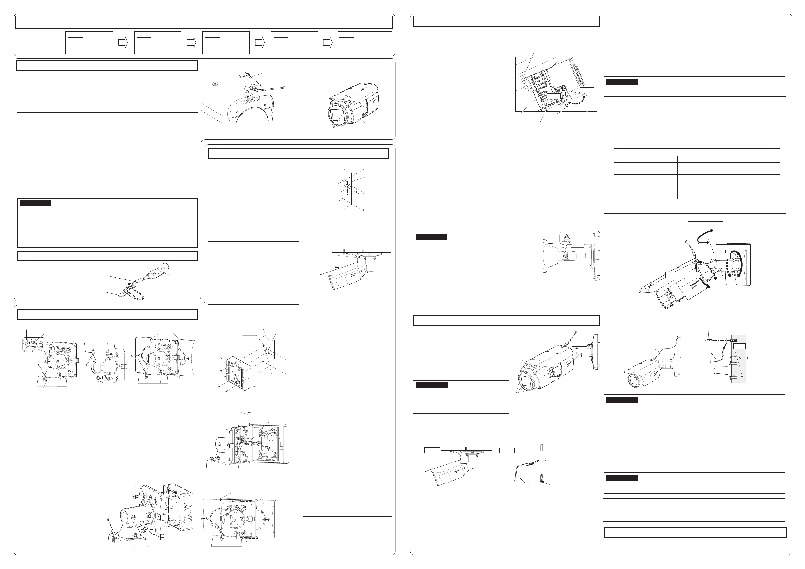
Pass the safety wire (
G
: accessory)
through the wire mounting hole in
the Safety wire
lug (I: accessory). Wire mounting hole
[1] Attaching the safety wire
[2] Remove the front cover
Installation
Step 2 Preparation
Step 4 Adjusting the camera 1, 2, 3, 4, 5
Step 4 Adjusting the camera (continued)
6
,
7
,
8
,
9
Step 1 Before starting the installation
The installation tasks
are explained using
5 steps.
Tear off the blue tape attached on camera arm before installing the camera.
There are 3 methods to install the camera to a ceiling or wall as described below. Prepare the
required parts for each installation method before starting the installation. The installation con-
ditions for mounting the camera are as follows.
Installation method
Recom-
mended
screw
Minimum pull-
out strength
[1]
Directly mount the camera onto the ceiling or wall
(when there is a space for wiring in the ceiling or the wall)
M5 screws
× 4
724 N {163 lbf}
(per 1 pc.)*1
[2]
Mount the camera to a junction box
* Only use metal junction boxes.
M4 screws
× 4*2
724 N {163 lbf}
(per 1 pc.)*1
[3]
Mount the camera onto the ceiling or wall using
WV-Q120A (Adapter box: approx. 510 g{1.13 lbs})
(when there is no space for wiring in the ceiling or the wall)
M5 screws
× 4*3
724 N {163 lbf}
(per 1 pc.)*1
*1 To mount the camera onto the ceiling or wall, the safety wire (G: accessory)
must be attached. Have an M6 bolt and nut or anchor bolts (with the minimum
pull-out strength of 724 N {163 lbf}) ready for securing the safety wire.
*2
Prepare a M4 screw with a washer with a diameter of 7.5 mm {5/16 inches} to
10 mm {3/8 inches} and a spring washer.
*3 The four screws (M5 × 20 mm {25/32 inches}) used to x this unit to WV-Q120A
come with WV-Q120A. For installation methods, refer to the operating
instructions of WV-Q120A.
1
Determine the position where the camera is to be mount-
ed on the ceiling or wall and drill a hole for securing the
camera and wiring as shown in the illustration to the right.
*
Determine the diameter and depth of the hole according to the
size of fixing screws or anchors (4 M5 screws, locally procured).
2
Connect the cables coming from the camera and coming through
the ceiling or wall according to the instructions in “Making con-
nections”. Waterproof the connections according to the instruc-
tions in “Waterproof treatment for the cable joint sections”.
3
Secure the camera to the ceiling or wall by attaching the 2 upper M5 screws or anchors
(M5 × 4, locally procured) and then the 2 lower ones into the holes on side B on the camera mount
bracket in the order shown in the illustrations above explanations [1]-1 to [1]-3 in the lower left.
4
Secure camera mount bracket covers (
A
: accessory) to the camera mount bracket by
using M3 × 6 mm {1/4 inches} Camera mount bracket cover fixing screws (
B
: accessory).
2Fit the Safety wire lug to the camera.
1Change the direction the camera is facing from directly down to facing up and
temporarily x the camera in place.
4Insert an SD memory card into the SD
memory card slot, if necessary.
Insert the SD memory card with its label
facing the lens.
2Fit a pin cable (locally procured) to the
MONITOR OUT jack on the camera and
connect an adjustment monitor.
6After adjusting the focus by pressing
the AF button, remove the adjustment
monitor.
9Remove the protection sheet on the front cover.
When the installation of the camera is complete, perform camera settings while
referring to the included “Congure the settings of the camera” (leaet).
7Mount the front cover to the camera,
and then fasten it with the 4 xing
screws.
* Fasten the front cover xing screws along
the diagonal direction.
8Secure the safety wire (G: accessory)
to the ceiling or wall.
■ When the camera is installed to the ceiling
■ When the camera is mounted on the wall
Note:
● Any of the PAN, TILT and YAW lock screw can be adjusted by loosening them about
1 turn. Do not unscrew them more than necessary.
● Make sure the camera is supported by hand when loosening lock screws and adjusting
the direction of the camera.
● When the camera is mounted on the wall, adjust the camera direction by turning the PAN,
TILT and YAW parts as shown in the illustration below.
●The range of angles that the camera portion can actually be turned to in regards to a wall
or ceiling is as follows.
Wall mounting Ceiling mounting
Angle Adjustment part Angle Adjustment part
Horizontal ±90 ° TILT rotation
part*
±180 ° PAN rotation
part
Vertical ±90 ° TILT rotation
part*
0 ° to 90 ° TILT rotation
part
Yaw from -190 ° to
+100 °
YAW rotation
part
from -190 ° to
+100 °
YAW rotation
part
* You can change between horizontal and vertical angles by adjusting the PAN
rotation part.
IMPORTANT:
●Avoid touching the tilting part near the warning label
when you change the tilting angle to secure the cam-
era.
●If the TILT or PAN lock screw is loosened, the camera
may not be held in place when it is secured to the
wall or ceiling. If this is the case, temporarily tighten
the appropriate lock screws to keep the camera from
moving.
IMPORTANT:
●Once the front cover is installed, the camera may be slightly out of focus. After installing
the front cover, use the auto focus via the settings menu.
IMPORTANT:
● After adjustment, be sure to tighten the PAN, TILT and YAW lock screws.
IMPORTANT:
●Each M6 bolt and nut or anchor (locally procured) for securing the safety wire
(G: accessory) must have the minimum pull-out strength of 724 N {163 lbf}.
●Be sure to secure the safety wire (G: accessory) to the foundation of a structure or an
area that is strong enough.
●Be sure to install the camera at least 2m 80 cm {9.2 feet} from the floor (the distance
between the lowest part of the installed camera and the floor).
●Attach the safety wire (G: accessory) so that if the camera were to become detached, it
would not fall on nearby people.
Step 1
Before starting the
installation
Step 2
Preparation
Step 3
Fixing the camera
Step 4
Adjusting the camera
Step 5
Conguring the settings of
the camera (see the leaet)
Safety wire lug
(I: accessory)
Safety wire
(G: accessory) Wire fitting
Recommended tightening torque: 0.59 N·m {0.44 lbf·ft}
*
The safety wire is not shown in the subsequent illustrations.
●To remove the SD memory card, hold
down the SD ON/OFF button for about 2
seconds. When the blinking SD MOUNT
indicator goes out, you can remove the SD
memory card.
●After the SD memory card has been
replaced, press the SD ON/OFF button
(for less than 1 second), and make sure
the SD MOUNT indicator is continually lit.
●If you do not press the SD ON/OFF button after replacing the SD memory card, the
SD MOUNT indicator is automatically lit approximately 5 minutes later.
5Adjust the camera eld of view.
Adjust the direction of the camera with the PAN, TILT and YAW rotation parts, and turn
the zoom knob until the desired field of view is achieved.
A)
Using a
5 mm {3/16 inches}
hex wrench (locally procured), loosen the PAN lock screw
on the base of camera arm. To direct the camera to the left, turn the camera arm part
clockwise when viewed from the front. To direct the camera to the right, turn it counter-
clockwise. (Panning range: ±180 °)
B) Using a 3 mm {1/8 inches} hex wrench (locally procured), loosen the TILT lock screw
in the middle of camera arm and roughly adjust the direction of the camera. (Tilting
range: 0 ° to 90 °)
C)Temporarily tighten PAN lock screw and TILT lock screw to prevent the camera from
moving.
D)Using a 5 mm {3/16 inches} hex wrench (locally procured), loosen the YAW lock
screw, turn the camera until the sunshield faces up and adjust the tilt of the camera.
(Yawing range: -190 ° to +100 °)
E) As shown in the left figure, insert the Auxiliary handle (J: accessory) into the zoom
knob and loosen the knob by rotating it to the left, and move it between TELE and
WIDE to obtain the desired field of view. Then, lock the zoom knob by rotating it
back to the right. Adjust the focus by pressing the auto focus (AF) button.
F) Adjust the camera angle and field of view by repeating steps A) through E). When
the desired angle and field of view are achieved, tighten the PAN lock screw,
TILT lock screw and YAW lock screw.
Recommended tightening torque
PAN lock screw: 2.7 N·m {2.0 lbf·ft}
TILT lock screw: 4.3 N·m {3.2 lbf·ft}
YAW lock screw: 2.7 N·m {2.0 lbf·ft}
Step 3 Fixing the camera
[1] Directly mount the camera onto the ceiling or wall
Note:
●When installing on a wall, install the
camera mount bracket so that “↑ TOP/
FRONT” faces upward.
●When installing on a ceiling, install the
camera mount bracket so that “↑ TOP/
FRONT” is aligned with the direction in
which the camera is pointed.
●When wiring cables on the side, use a
nipper to cut open a side cable access
hole of the camera mount bracket cover,
and then pass the cable through.
Step 3 Fixing the camera (continued from upper right)
[1]-1
Loosen the TILT lock
screw by about 1 turn until
the camera faces downward
and then temporarily tighten
the TILT lock screw. After
this, use the 2 upper M5
screws (locally procured) to
secure the camera.
[1]-2
Loosen the PAN lock
screw about 1 turn until the
camera faces upward and
then temporarily tighten the
PAN lock screw. After this,
use the 2 lower M5 screws
(locally procured) to secure
the camera.
[1]-3 Using the camera mount
bracket cover fixing screws
(B: accessory), install the
camera mount bracket cover
(A: accessory) with the cam-
era facing downward.
Recommended tightening torque:
0.59 N·m {0.44 lbf·ft}
1
Secure the adapter box to the wall.
●Drill pilot holes and a cable hole (see the illus-
tration to the left for their dimensions). (Drill
pilot holes only if making connections through
the cable hole from the side.)
●Be sure to face “TOP” inside the Q120A upward.
●Use 4 screws (M5: locally procured) to directly
secure the Q120A to the wall. Minimum pull-out
strength: 724 N {163 lbf} (per 1 pc.)
●To install this product outdoors, be sure to water-
proof the cable access hole and screw holes.
2
Temporarily secure the camera mount bracket
and camera to the Q120A.
● After referring to [1]-1 and adjusting the camera
to face down, temporarily secure the camera,
and then use the M4 × 35 mm {1- 3/8 inches}
Adapter box mounting screw (Q120A accessory)
for installing the camera to temporarily install the
camera mount bracket to the left or right hinge of
the Q120A so that it can be opened and closed.
● Secure the camera mount bracket with “↑TOP/
FRONT” facing upward.
●When the wall is on one side or the other,
install the adapter box to the hinge on the
opposite side of the wall.
●Secure the camera mount bracket to the hinge
of the Q120A using the following tightening
torque. Recommended tightening torque:
0.78 N·m {0.58 lbf·ft}
3Connect the cables.
●Connect the cables coming from the camera and
coming through the wall according to the instruc-
tions in “Making connections”.
●Waterproof the connections according to the
instructions in “Waterproof treatment for the
cable joint sections”.
4
Secure the camera mount bracket to the Q120A.
●Using 4 M5 × 20 mm {13/16 inches} Mounting
screws for adapter box (Q120A accessory),
secure the camera mount bracket to the
Q120A via the holes in side A of the camera
mount bracket in the order of the top 2 holes to
bottom 2 holes. Recommended tightening
torque: 1.86 N·m {1.37 lbf·ft}
(Refer to [1]-1 and [1]-2.)
●Using 2 M3 × 6 mm {1/4 inches} camera mount
bracket cover fixing screws (B: accessory), secure
the Camera mount bracket cover (A: accessory)
to the Camera mount bracket. Recommended
tightening torque: 0.59 N·m {0.44 lbf·ft}
* The following explains an example of mounting the
camera on a wall.
[2] Mount the camera to a junction box
[3] Mount the camera onto the ceiling or wall using WV-Q120A (Adapter box:
Optional accessory) (Hereinafter WV-Q120A is referred to as Q120A.)
As shown in the illustration to the right,
install the camera to a junction box using
4 M4 xing screws (locally procured) via
the holes in side B of the camera mount
bracket. (Minimum pull-out strength:
724 N {163 lbf} (per 1 pc.))
Note:
●The procedure for fitting screws in the holes
for connections and fixing screws is the
same as for 2, 3, and 4in [1] Directly
mount the camera onto the ceiling or wall.
● When junction boxes or the like are used, it
is recommended that 2 pieces be used side
by side. (Securing the camera to one junction
box and making connections to the other
makes cable connections easy.)
TOP
46 mm {1-13/16 inches}
83.5 mm
{3-5/16 inches}
24.5 mm
{15/16 inches}
6 mm {1/4 inches} wide ×
10 mm {3/8 inches}
length hole
Cable access hole
(The female thread for conduit is compliant
with ANSI NPSM (parallel pipe threads) 3/4
or ISO 228-1 (parallel pipe threads) G3/4.)
Screws × 4
(M5, locally
procured)
Center of the adapter
box
Cable access hole
↑TOP mark (internal)
WV-Q120A (Adapter box :
Optional accessory)
ø30 mm
{1-3/16 inches}
23 mm {29/32 inches}
When the camera has been installed, remove the protection sheet from the front
cover. After removal, be sure not to touch the clear part of the front cover.
Note:
●When removing the camera, perform removal by following the installation procedure in
the reverse order.
Step 5 Configuring the settings of the camera (see the leaflet)
46 mm
{1-13/16 inches}
83.5 mm
{3-5/16 inches}
35 mm
{1-3/8 inches}
Cable access
hole ø30 mm
{1-3/16 inches}
23 mm
{29/32 inches}
* M5 × 4 screws, Minimum pull-out strength: 724 N {163 lbf} (per 1 pc.). Secure the
camera through the holes in side B of the camera mount bracket.
M6 bolt and nut or anchor
(locally procured)
Safety wire
(G: accessory)
Ceiling
Safety wire
(G: accessory)
M6 bolt and nut or anchor
(locally procured)
Wall
IMPORTANT:
●Securely tighten the 4 front cover fixing
screws. Failure to do so may cause the cam-
era to fall or waterproof failure.
Recommended tightening torque: 0.59 N·m
{0.44 lbf·ft}
3Turn on the camera.
* Do not adjust the PAN
rotation part more than
±180 °. This may cause
cables to be wrenched.
IMPORTANT:
●For the screws or anchor bolts used in the above methods ([1] to [3]), be sure to secure
the minimum pull-out strength of 724 N {163 lbf} per screw or bolt.
●Select screws according to the material of the ceiling or wall that the camera will be
mounted to. In this case, wood screws and nails should not be used.
●If a ceiling or wall board such as plaster board is too weak to support the total weight,
the area shall be sufficiently reinforced.
● Because the front cover is temporarily removed when installing or adjusting the camera,
make sure no liquid enters the camera at these times.
Wire lug fixing screw
(H: accessory)
Safety wire lug
(I: accessory)
Loosen the four front cover fixing screws
and remove the front cover.
Example: When mounting on a ceiling
Direction in which the
camera is pointed
Direction in which
“↑TOP/FRONT” is pointed
Camera mount bracket
cover fixing
screws
(
B
:
accessory) × 2
Mounting screws for adapter box
(Q120A accessory) × 4
Side A
(lower)
Camera mount bracket cover
(A: accessory) × 2
WV-Q120A (Adapter box :
Optional accessory)
↑TOP/FRONT mark
(on the front)
Camera mount bracket
Adapter box mounting
screw (Q120A accessory)
M4 × 35 mm {1- 3/8 inches} hinges
M5 × 2
(locally procured)
Camera mount bracket cover
(A: accessory)
Camera mount
bracket cover
fixing screws
(
B
: accessory)
Side B (upper)
M5 × 2
(locally procured)
↑ TOP/FRONT mark
Camera
mount
bracket
PAN lock screw
TILT lock
screw
Side B (Upper)
Junction
box
Camera
mount bracket
46 mm
{1-13/16 inches}
83.5 mm
{3-5/16 inches}
TILTrotationpart
PANrotationpart
Cameraarmpart
YAWrotationpart
YAW lock
screw
PAN lock screw
TILT lock
screw
Front cover
Front cover fixing screws×4
Ceiling
Safety wire
(G: accessory)
Wall
Safety wire
(G: accessory)
Auto focus
(AF) button Zoom knob
MONITOR OUT jack
SD memory card
(Ensure that the label faces the lens.)
TELE
Auxiliary handle
(J: accessory)
WIDE
Front cover fixing screws × 4
Front cover
Warning label

This manual suits for next models

1

Other Panasonic Security Camera manuals

Panasonic WV-CP290/G User manual

Panasonic

Panasonic WV-CP290/G User manual

Panasonic BB-HCM581CE User manual

Panasonic

Panasonic BB-HCM581CE User manual

Panasonic EggCam GP-KR001 User manual

Panasonic

Panasonic EggCam GP-KR001 User manual

Panasonic WV-X5550LT User manual

Panasonic

Panasonic WV-X5550LT User manual

Panasonic WV-SFN130 User manual

Panasonic

Panasonic WV-SFN130 User manual

Panasonic WVCP460 - COLOR CCTV CAMERA User manual

Panasonic

Panasonic WVCP460 - COLOR CCTV CAMERA User manual

Panasonic AK-HC1800G User manual

Panasonic

Panasonic AK-HC1800G User manual

Panasonic WV-CW240S User manual

Panasonic

Panasonic WV-CW240S User manual

Panasonic WVNP244 - COLOR CCTV CAMERA User manual

Panasonic

Panasonic WVNP244 - COLOR CCTV CAMERA User manual

Panasonic WV-CW594 User manual

Panasonic

Panasonic WV-CW594 User manual

Panasonic WV-NP304E User manual

Panasonic

Panasonic WV-NP304E User manual

Panasonic WV-CS580 User manual

Panasonic

Panasonic WV-CS580 User manual

Panasonic WV-CP630 User manual

Panasonic

Panasonic WV-CP630 User manual

Panasonic WVNS954 - NETWORK CAMERA User manual

Panasonic

Panasonic WVNS954 - NETWORK CAMERA User manual

Panasonic WV-CP290 series User manual

Panasonic

Panasonic WV-CP290 series User manual

Panasonic VIDEOLARM PCF3 Instruction sheet

Panasonic

Panasonic VIDEOLARM PCF3 Instruction sheet

Panasonic AWE300S - SEPERATE CAMERA User manual

Panasonic

Panasonic AWE300S - SEPERATE CAMERA User manual

Panasonic VL-CM851BX User manual

Panasonic

Panasonic VL-CM851BX User manual

Panasonic WVCS564 - COLOR CCTV CAMERA User manual

Panasonic

Panasonic WVCS564 - COLOR CCTV CAMERA User manual

Panasonic WV-CF284 Series User manual

Panasonic

Panasonic WV-CF284 Series User manual

Panasonic WV-CF224EX User manual

Panasonic

Panasonic WV-CF224EX User manual

Panasonic WV-CW590A User manual

Panasonic

Panasonic WV-CW590A User manual

Panasonic WV-SF138 Installation and operation manual

Panasonic

Panasonic WV-SF138 Installation and operation manual

Panasonic GPUS522HA - IND CCD CAMERA User manual

Panasonic

Panasonic GPUS522HA - IND CCD CAMERA User manual

Popular Security Camera manuals by other brands

Samsung SCC-B2335 SCC-B2035P user manual

Samsung

Samsung SCC-B2335 SCC-B2035P user manual

ARH PARKIT install guide

ARH

ARH PARKIT install guide

SCS DWS SERIES Installation and operating instruction manual

SCS

SCS DWS SERIES Installation and operating instruction manual

Global BD-300G manual

Global

Global BD-300G manual

Hanwha Techwin Bandit Barrier XNB-H6280B quick guide

Hanwha Techwin

Hanwha Techwin Bandit Barrier XNB-H6280B quick guide

ORION Images CHDC-34BSDC Installation and user guide

ORION Images

ORION Images CHDC-34BSDC Installation and user guide

Eneo ICB-62M2712M5A user manual

Eneo

Eneo ICB-62M2712M5A user manual

Wisenet PNM-9084RQZ quick guide

Wisenet

Wisenet PNM-9084RQZ quick guide

OPTICOM PT-360-27 - SPECIFICATION DATA specification

OPTICOM

OPTICOM PT-360-27 - SPECIFICATION DATA specification

Storm VUDO2PTZIR30X installation manual

Storm

Storm VUDO2PTZIR30X installation manual

Moog CVFC2-S25 Installation and operation instructions

Moog

Moog CVFC2-S25 Installation and operation instructions

Airlink101 AIC1620W Quick installation guide

Airlink101

Airlink101 AIC1620W Quick installation guide

Vivotek IP7133 Specifications

Vivotek

Vivotek IP7133 Specifications

Stobo 51058 user manual

Stobo

Stobo 51058 user manual

Concept Pro CP-HSD10-IP quick start guide

Concept Pro

Concept Pro CP-HSD10-IP quick start guide

Vivotek PT3114 Quick installation guide

Vivotek

Vivotek PT3114 Quick installation guide

Dahua K Series quick start guide

Dahua

Dahua K Series quick start guide

Interlogix UVP-M1120P-18X-N user manual

Interlogix

Interlogix UVP-M1120P-18X-N user manual

manuals.online logo
manuals.online logoBrands
  • About & Mission
  • Contact us
  • Privacy Policy
  • Terms and Conditions

Copyright 2025 Manuals.Online. All Rights Reserved.