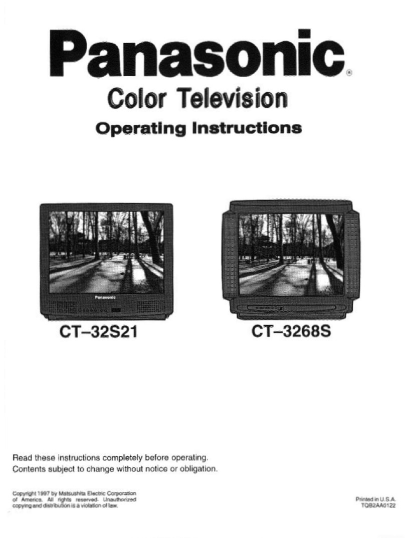
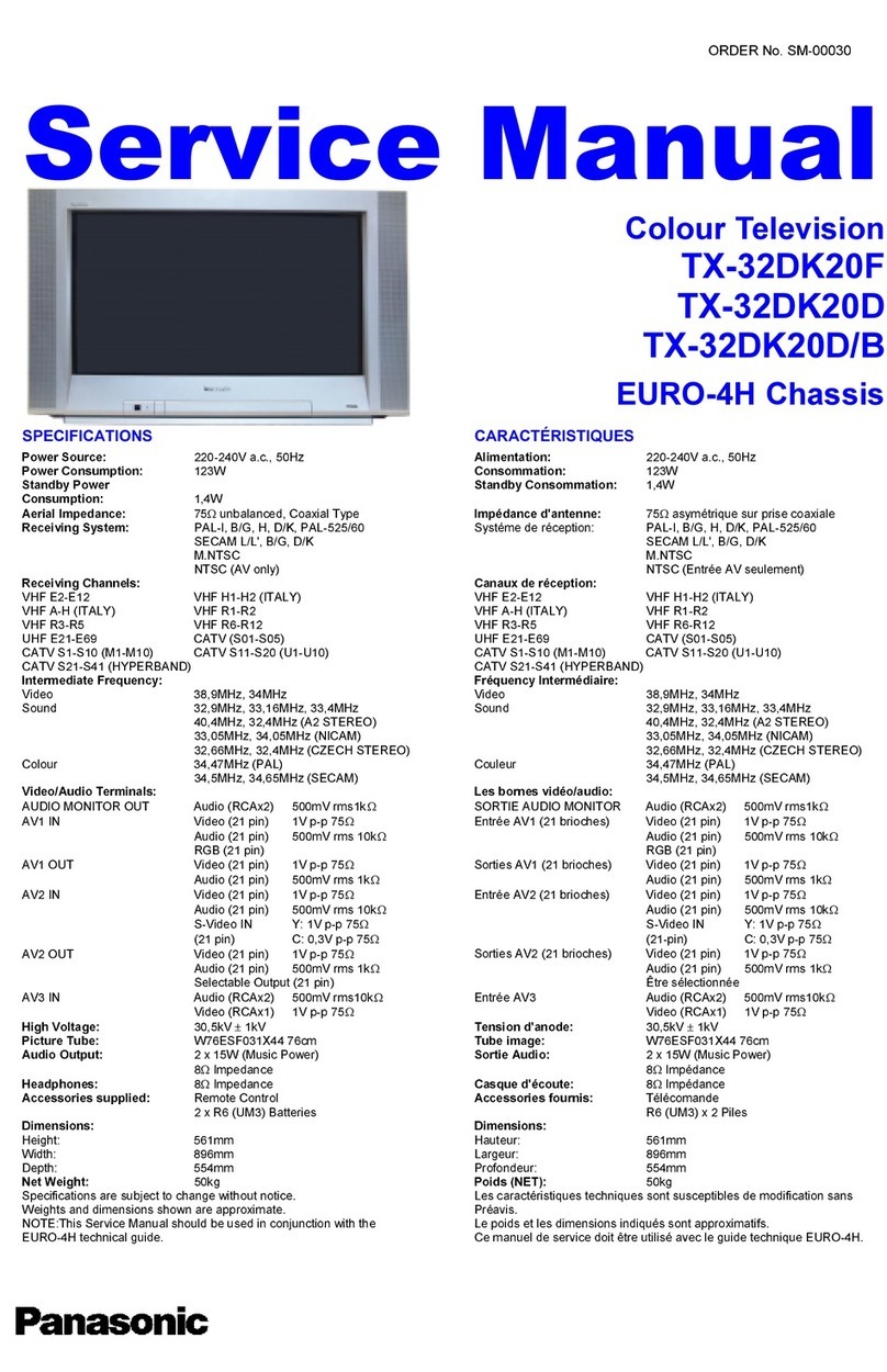
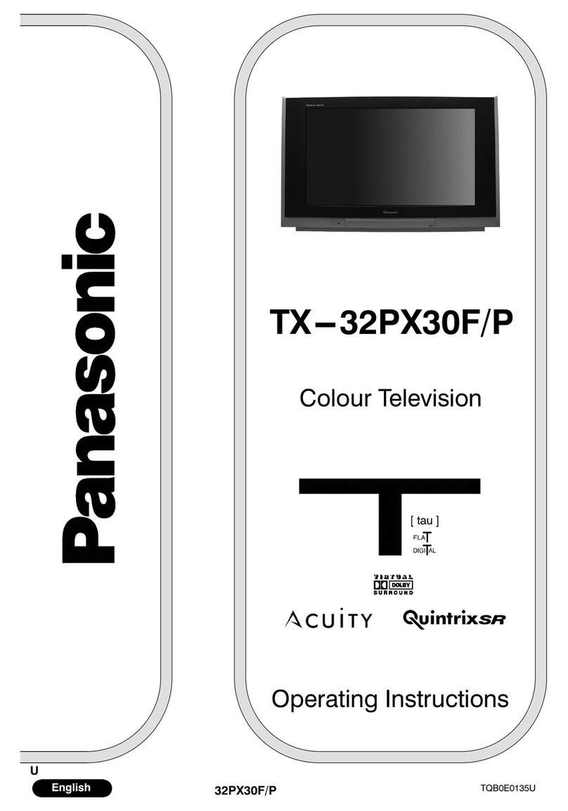
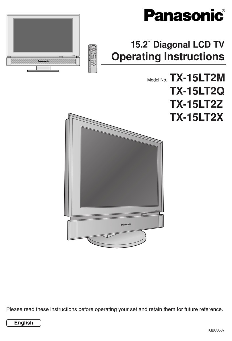
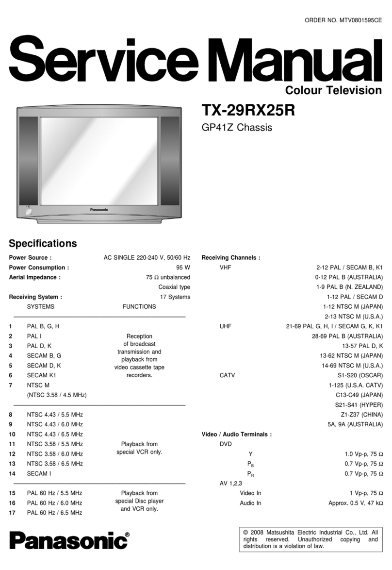
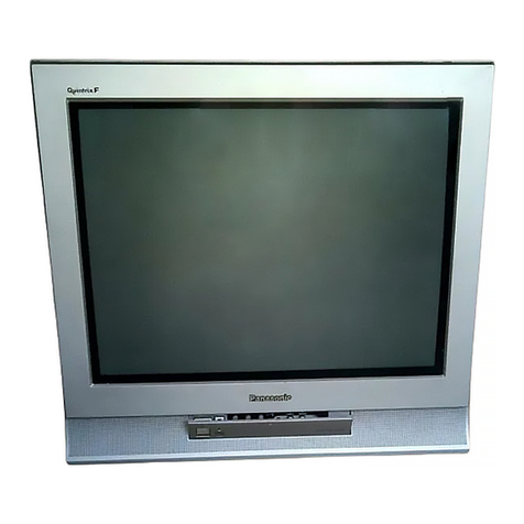
Panasonic TX-W32D4DP User manual

Service Support
Service and repair of
this product is
supported by
Panasonic's LUCI
interface.
This interface provides a
link between the TV and
a standard PC to allow a
number of diagnostic
and control functions to
be performed.
For more details contact
your local Panasonic
company.
BACK
EXIT
TX-W32D4DP Service Manual
Safety
Specifications Block Diagrams
Schematic Diagrams
PCB Views
Self Check
Service
Information
Parts List
Service Hints
Disassembly
Location of
Controls
Waveforms
Mechanical
View
Adjustments

BACK
BACK
BACK
M - Schematic
H - Schematic
F - Schematic
D - Schematic
Y - Schematic
K - Schematic
G - Schematic
E - Schematic
H - PCB
M - PCB
K - PCB
Y - PCB
F - PCBs G - PCB
D - PCB E - PCB
Power supply
Audio
Video
Control

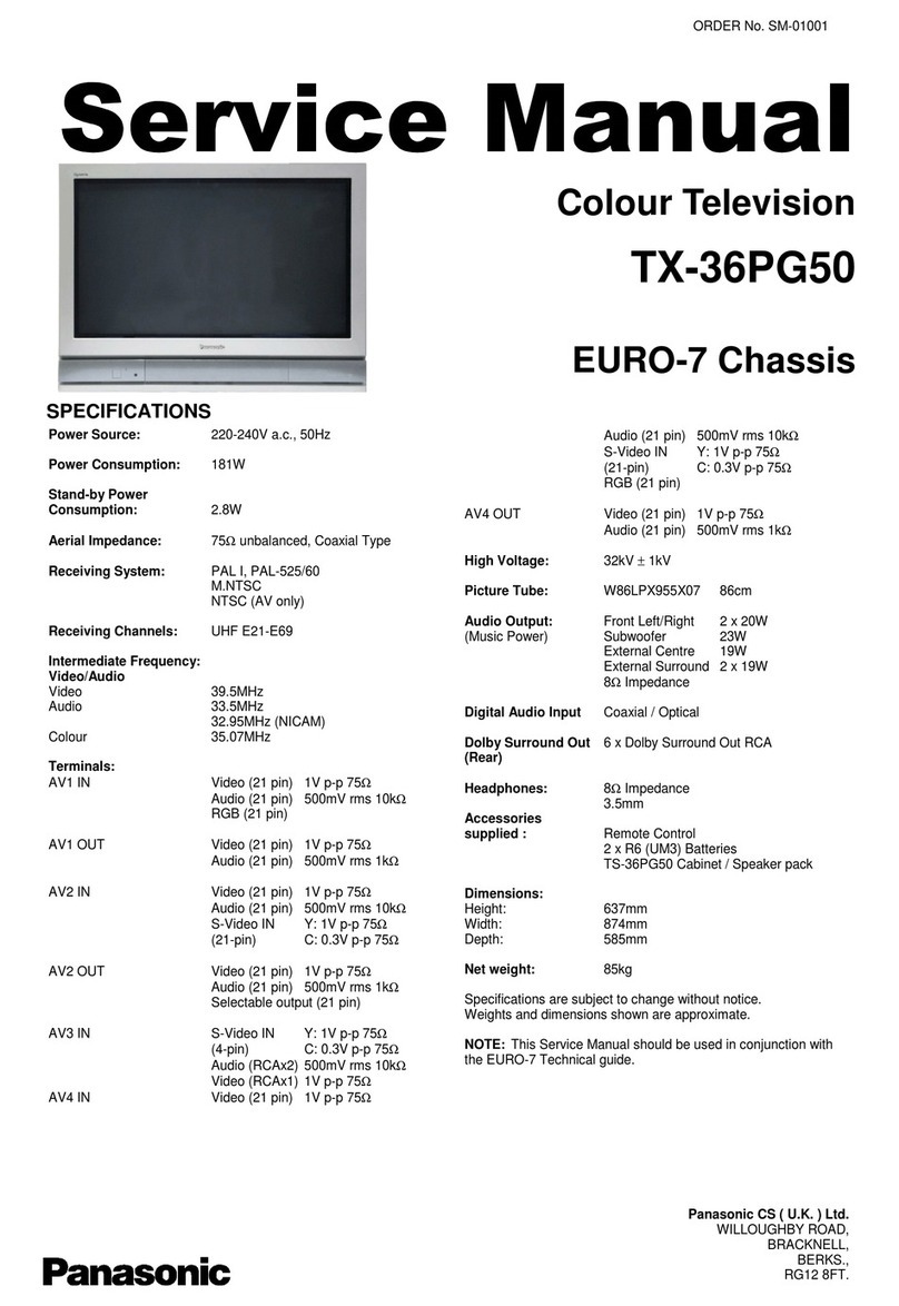
Colour Television
TX-W32D4DP
EURO-5 Chassis
SPECIFICATIONS
Power Source: 220-240V a.c., 50Hz
Power Consumption: 200W
Aerial Impedance:75Ωunbalanced, Coaxial Type
Stand-by Power
Consumption:1,9W
Receiving System:PAL I, PAL 525/60
M.NTSC
NTSC (AV only)
Receiving Channels: UHF E21-E69
Intermediate Frequency:
Video 39,5MHz
Audio33,5MHz, 32,95MHz
Colour 35,07MHz
Video/Audio
Terminals:
AV1 IN Video (21 pin) 1V p-p 75Ω
Audio (21 pin) 500mVrms 10kΩ
RGB (21 pin)
AV1 OUT Video (21 pin) 1V p-p 75Ω
Audio (21 pin) 500mVrms 1kΩ
AV2 IN Video (21 pin) 1V p-p 75Ω
Audio (21 pin) 500mVrms 10kΩ
S-Video IN Y: 1Vp-p 75Ω
(21 pin) C: 0.3V p-p 75Ω
AV2 OUT Video (21 pin) 1V p-p 75Ω
Audio (21 pin) 500mVrms 1kΩ
Selectable Output (21 pin)
AV3 IN S-Video IN Y: 1Vp-p 75Ω
(4-pin) C: 0,3V p-p 75Ω
Audio(RCAx2) 500mVrms10kΩ
Video (RCAx1) 1V p-p 75Ω
AV4 IN Video (21 pin) 1V p-p 75Ω
Audio (21 pin) 500mVrms 10kΩ
S-Video IN Y: 1Vp-p 75Ω
(21 pin) C: 0.3V p-p 75Ω
AV4 OUT Video (21 pin) 1V p-p 75Ω
Audio (21 pin) 500mVrms 1kΩ
DolbySurround Out 6 x Dolby Surround Out RCA
(Rear)
External Speaker
connections 2 x Rear
1 x Centre
High Voltage: 31kV ±1kV
Picture Tube:W76LFC185X05 76cm
Audio Output:Front Left/Right 2 x 20W
(Music Power) External Centre 16W
3D Bass 26W
Surround 2 x 16W
8ΩImpedance
Headphones:8ΩImpedance
3,5 mm
Accessories
supplied : Remote Control
2 x R6 (UM3) Batteries
TS-400DP Video cabinet / Speaker pack
Dimensions:
Height:555 mm
Width: 862 mm
Depth: 553 mm
Net weight:52kg
Specifications are subject tochange without notice.
Weights and dimensions shown are approximate.
NOTE: ThisService Manual should be used in conjunction
with the EURO-5 Technical Guide.
ORDER No. SM-98073
Panasonic CS ( U.K. ) Ltd.
WILLOUGHBYROAD,
BRACKNELL,
BERKS.,
RG12 8FT.

CONTENTS
SAFETY PRECAUTIONS..........................................................................................................................................................2
SERVICE HINTS.......................................................................................................................................................................3
SERVICE POSITION.................................................................................................................................................................4
ADJUSTMENT PROCEDURE AND SELF-CHECK ..................................................................................................................5
WAVEFORM PATTERN TABLE ...............................................................................................................................................6
ALIGNMENTSETTINGS...........................................................................................................................................................7
BLOCK DIAGRAMS..................................................................................................................................................................8
PARTSLOCATION.................................................................................................................................................................12
REPLACEMENTPARTS LIST................................................................................................................................................13
SCHEMATIC DIAGRAMS.......................................................................................................................................................30
CONDUCTOR VIEWS.............................................................................................................................................................39
SAFETY PRECAUTIONS
GENERAL GUIDE LINES
1. It is advisable to insert anisolation transformer in the
a.c. supply before servicing a hot chassis.
2. When servicing, observe the original lead dress in the
high voltage circuits. If a short circuit is found, replace
all parts that have been overheated or damaged by
the short circuit.
3. After servicing, see that all the protective devices
suchasinsulationbarriers, insulation papers, shields
and isolation R-C combinations are correctly
installed.
4. When the receiver is not being used for a long period
of time, unplug the power cord from the a.c. outlet.
5. Potentials ashigh as32kV are present when this
receiver is in operation.Operation of the receiver
without the rear cover involves the danger of a shock
hazard fromthe receiver power supply. Servicing
should not beattempted by anyone who isnot
familiar with the precautions necessary when working
on high voltage equipment. Always discharge the
anode of the tube.
6. After servicing make the following leakage current
checks to prevent the customer frombeing exposed
to shock hazard.
LEAKAGE CURRENT COLD CHECK
1. Unplug the a.c. cordand connect a jumper between
the two prongs ofthe plug.
2. Turn on the receiver’spower switch.
3. Measure the resistance value with anohmmeter,
between the jumpereda.c. plug and each exposed
metallic cabinet part onthe receiver, such asscrew
heads, aerials, connectors, control shaftsetc. When
the exposed metallic part has a return path to the
chassis, the reading should bebetween 4M ohm and
20M ohm. When the exposed metal does not have a
return path to the chassis, the reading must be
infinite.
LEAKAGE CURRENT HOT CHECK
1. Plug the a.c. cord directly into the a.c. outlet. Donot
use an isolation transformer for this check.
2. Connect a 2kΩ10W resistor in series with an
exposed metallic part on the receiver and an earth,
suchasa water pipe.
3. Use an a.c.voltmeter with high impedance to
measure the potentialacrossthe resistor.
4. Check each exposed metallic part and check the
voltage at each point.
5. Reverse the a.c. plug at the outlet and repeat each of
the above measurements.
6. The potential at any point should not exceed
1,4 Vrms. Incase a measurement is outsidethe limits
specified, there is a possibility of a shock hazard, and
the receiver should be repaired and rechecked before
it is returned to the customer.
X-RADIATION WARNING
1. The potential sources of X-Radiation inTVsets are
the high voltage section and the picture tube.
2. When using a picture tubetest jig for service, ensure
that the jig is capable of handling 32kV without
causing X-Radiation.
NOTE: It is important to use an accurateperiodically
calibratedhigh voltage meter.
1. Set the brightness to minimum.
2. Measure the high voltage. The meter should
indicate :- 31kV ± 1kV. Ifthe meter indication is out of
tolerance,immediate service and correction is
required to prevent the possibility of premature
component failure.
3. To prevent any X-Radiation possibility, it isessential
to use the specified tube.
HOT CHECK CIRCUIT
A.C. VOLTMETER
WATER PIPE
(EARTH)
TO INSTRUMENT’S EXPOSED
METALLIC PARTSFig. 1.
2kΩ10 Watts
2
SERVICE HINTS
How toremove the rear cover
1. Removethe 10 screwsas shown in Fig.2.
LOCATION OF CONTROLS
3
SCREWS
Fig.2.
G - Board E - Board D- Board
Focus
Screen
H - Board
Fig.3.
F - Board
Y - Board
K - Board
M- Board

HOW TO MOVE THE CHASSIS INTO SERVICE POSITION
1. Hold and lift the rear of the E-PCB chassis and gently pull the chassis toward you, asshown in Fig.4.
2. Release the respectivewiring clips and rotatethe chassis vertically through 90°, anti-clockwise.
3. Locate the base of the chassis frame into the hole (B), shown in Fig.6.
4. Clip the chassis frame onto the bead clamper, shown in Fig.5.
5. After servicing replace the bead clamper and ensure all wiring isreturnedto its originalposition before returning the
receiver to the customer.
Fig.4.
Fig.5.
Fig.6.
(
B
)
4
(
A
)

ADJUSTMENT PROCEDURE
Item / Preparation Adjustments
+B SET-UP
1. Receive a Greyscale signal.
2. Set the controls:-
Brightness Minimum
Contrast Minimum
Volume Minimum
1. Confirm the following voltages.
D-Board E-Board
D3 PIN5147V ± 3V U8A E19-PIN88V ± 0,5V
D12 PIN5 5V ± 0,3V U9 IC3801-PIN39V ± 0,5V
D13 PIN140V ± 4V U12 E22-PIN812V ± 0,5V
D3 PIN4230V ±10V STD5VE26-PIN45V ± 0,5V
D3 PIN4205V ±10V U15 E23-PIN815V ± 1V
D3 PIN4190V ±10V U15 E23-PIN9-15V ± 1V
D3 PIN4190V ±10V U33 E22-PIN10 33V ± 4V
D14 PIN5 5V ± 0,5V U40 E24-PIN140V ± 3V
D12 PIN715V ± 2V U5B E19-PIN55V ± 0,5V
D12 PIN915V ± 2V
D11 PIN812V ± 2V
D11 PIN10 33V ± 3V
Cut Off
1. Receive a Greyscale signal.
2. Degauss the tube externally.
3. Set the TVinto Service Mode 1.
4. SelectCut off mode.
Adjustthe screen VR until the display shows "O.K."
FACTORY SETTINGS
To return customer settings tofactory settings and clear owner ID ofall information input by the customer, enter Self-Check
mode. Pressthe down (-/v)button onthe customer controlsat the front of the TVset,at the same time pressing the STATUS
button on the remote control. Toexit Self Check, switch off the TVset atthe power button.
Self Check is also used to automatically check the bus lines and hexadecimalcode of the TVset. If the CCU ports have
been checked and found to beincorrect or not located then " - - " will appear in place of "O.K.". For more in-depth TV
diagnostics use the LUCI interface as listedbelow.
Service Aids
To aid in the service of our current chassis there are a number of Service Aids which have been made available.
•LUCI interface kit (Linked Utility Computer Interface)
Part number: TZS6EZ002
This contains interface and cablesfor connecting TVservice connector and a PC aswell asdiagnostic software. As new
models are introduced upgrade software will becomeavailable.
•VICI (Visual Interactive Computer Information)
These C.D.'s contain multimedia documentation providing quick access to service information.
Part No. TZS7EZ006 & TZS7EZ005
1. Service Manuals
2. Instruction Books
3. Technical Information
•TASMIN (Technically Advanced System forMultimedia Interactive Notes)
As well as providing a first step towards more interactive trainingthis product also achieves quick access to Technical
Information.
5
NOTE: Self Check should onl
y
beused when refurbishin
g
the TVset and not durin
g
normal repair work.
PCB O.K.
Cab O.K.
Sum Factory use
only
VPC O.K.
TUN O.K.
E2 O.K.
DPL O.K.
CIP1 O.K.
CIP2 O.K.
VP O.K.
DFU O.K.
COL O.K.
PIP O.K.
OPTION 1 B9
OPTION 2 FD
OPTION 3 1F
OPTION 4 0D
OPTION 5 FB
OPTION 6
63

WAVEFORM PATTERN TABLE
NOTE: All waveforms have been taken using a standard colour bar pattern.
6
B - Out
IC601 Pin 42
2.2V
32µS
R - Out
IC601 Pin 40
32µS
2.2V
G - Out
IC601 Pin 41
2.2V
32µS
Vert Drive
IC451 Pin 2
8mS
63V
Vert Out
IC601 Pin 1
8.6mS
0.6V
VFLB
IC451 Pin 5
1V
8.6mS
Video In
IC1101 Pin 68
0.9V
64µS
H - Out
IC601 Pin 8
3.9V
32µS
HFLB
IC601 Pin 13
32µS
7V
32µS
1V
R - Y
IC601 Pin 26
Luminance In
IC601 Pin 28
0.9V
32µS
B - Y
IC601 Pin 27
32µS
1.3V
28µS
6V
H - Out
IC3901 Pin 3 V - Out
IC3901 Pin 21
0.1V
32µS
E/W- Out
IC601 Pin 3
280mV
8.5mS

ALIGNMENT SETTINGS:
(The figuresbelow are nominal and usedfor representative purposes only.)
1. Set the Bass to maximum position, set the Treble to minimum position, press the down button (- / v)on the customer
controls at the front ofthe TVand at the same time press the INDEX button on the remote control, thiswill place the TV
into the Service Mode.
2. Press the RED / GREEN buttonsto step up/ down through the functions.
3. Press the YELLOW / BLUE buttonstoalter the function values.
4. Press the STR button after each adjustment has been made to store the required values.
5. To exit the Service Mode, press the "N" button.
Alignment Function Settings / Special features
Horizontal PositionH-Pos
+020 Optimum setting.
Vertical Position V-Pos
+024 Optimum setting.
Horizontal Amplitude H-Amp
+049 Optimum setting.
Vert. Amplitude V-Amp
+029 Optimum setting.
EW-amplitude E/W-Amp1
+022 Optimum setting.
EW-amplitude E/W-Amp2
+000 Optimum setting.
Trapezium-comp Trapez-1
+033 Optimum setting.
Horizontal-Parallel H-Parallel
+032 Optimum setting.
Vertical Linearity V-Lin
+004 Optimum setting.
DVCO DVCO
000
Receive a PAL Colour Bar Pattern. For
DVCO alignment press "Blue" button, wait
until the colours are stable and press
"STR".
Cut-off DC Cut-off
O.K.
To adjust Cutoffadjustthe screen VR until
the display shows "O.K."
Highlight High 0031 0031 0031
Contrast Maximum
A.I. Off
Optimum setting.
Sub-Brightness Sub-Brightness
000 Optimum setting.
7

,
&
$9 &LQ
0DLQ <9
$9
2XW
0DLQ &RXW
9RXW
&RXW $9
79,Q
$9
,Q
$9 9LQ
$9 &LQ
$9 9LQ
$9 &LQ
$9 9LQ
4
4
4
4
4
4
4
4
,
&
&
9
%
6
,
Q5
*
%
(
(
(
(
(
(
,
&
5
*
%
<
%
<
5
<5
R*
R%
R
)
4
4
9
L
Q
&
L
Q
3
L
Q
V
3
L
Q
V
9
3
&
,
&
)
4
4
4
4
4
4
3
L
Q
V
3
L
Q
V
5
*
%
3
L
Q
V
3
L
Q
V
&
,
3
,
&
3
L
Q
V
3
L
Q
V
9
3
6
,
&
3
L
Q
V
3
L
Q
V
'
)
8
,
&
3
L
Q
V
0
H
P
R
U
\
,
&
3
L
Q
V
Q
G
&
,
3
,
&
3
L
Q
V
3
L
Q
V
3
L
Q
V
3
L
Q
V
3
L
Q
V
3
L
Q
V
3
L
Q
V
3
L
Q
V
3
L
Q
V
3
L
Q
V
4
4
4
4
4
4
4
4
4
+
+
$
9
4
4
$
9
$
9
0
9
&
<
$
9
<
,
&
5
R
X
W
,
&
%
R
X
W
,
&
*
R
X
W
4
4
&
&
<
<
8
9
8
9
<
<
<
<
8
9
8
9
8
9
8
9
<
<
+
'
5
L
Q
/
'
5
R
X
W
/
'
5
L
Q
<
R
X
W
8
R
X
W
9
R
X
W
0
%
R
D
U
G
+
%
R
D
U
G
<
%
R
D
U
G
(
%
R
D
U
G
)
%
R
D
U
G
4
9
L
Q
&
L
Q
9
R
X
W
9
L
Q
&
L
Q
9
R
X
W
9
L
Q
5
L
Q
9
R
X
W
*
L
Q
%
L
Q
7
X
Q
H
U
,
)
&
5
7
9,'(2 %/2&. ',$*5$0

,
&
0
6
3
,6&/
,6:6
,6',
,6'2
+3B5
+3B/
63.
6&
6&
4
(
(
(
(
(
*
*
,
&
$
9
0
5
/
$
9
0
%
R
D
U
G
*
%
R
D
U
G
(
%
R
D
U
G
5
63. /
6&
6&
6&
6&
6&
6&
6&
/LQ
5LQ
/LQ
5LQ
/LQ
6& 5LQ
6& /LQ
6& 5LQ
0RQR
063
5RXW
/RXW
/RXW
5RXW
4
4
,
&
/LQ
5LQ
5RXW
/RXW
4
4
4
4
(
7
R
6
3
.
,
&
/LQ
5LQ
5RXW
/RXW
4
4
+
3
,6&/
,6:6
,6'2
,6',
4
4
4
6/$
&$
:RRIHU
'
3
/
+
+
$
9
$
9
4
4
4
4
4
,
&
,
&
6
5
6
/
/
5
&6
:
+
(
.
.
,
&
,
&
,
&
,
&
.
4
4
4
4
4
4
7
R
'
6
3
.
/
5&
H
Q
W
U
H
6
5
6
/
:
R
R
I
H
U
7
R
6
X
U
U
R
X
Q
G
6
3
.
$
X
G
L
R
0
R
Q
L
W
R
U
2
X
W
-
.
6
:
5
5
5
/
&
5
/
-
.
&
-
.
-
.
/
5
5
R
5
L
/
L
/
R
5
R
5
L
/
L
/
R
5
R
5
L
/
L
/
R
+
%
R
D
U
G
.
%
R
D
U
G
4
7
X
Q
H
U
,
)
;
;
$8',2 %/2&.',$*5$0

(
(
(
(
(
*
*
+
+
$
9
$
9
$
9
0
0
%
R
D
U
G
+
%
R
D
U
G
,
&
4
5HVHW
'.,
:5
5'
$
$
36(1
'
'
)
%
/
.
$
$
:
5
5
'
4
4
,
&
6
5
$
0
$
$
3
6
(
1
4
4
,
&
(
3
5
2
0
//
3261(*
/('
+392/
//
31
7
X
Q
H
U
,
&
+
3
$
0
3
9
R
O
6
'
$
6
&
/
6
'
$
6
&
/
6&/
6'$
4
4
,
&
,
&
,
&
,
&
6
0
R
G
H
*
(
2
0
$
*
3
U
R
W
H
F
W
5
&
$
9
/
L
Q
N
,
Q
$
9
/
L
Q
N
2
X
W
6
O
R
Z
$)&
.H\6FDQ
6ORZ
6ORZ
9'HW
567
21
)6:
6&/
6'$
567
6&/
6'$
6&/
6&/
6'$
6'$
4
,
&
$)&
6'$
6&/
4
4
4
4
,
&
'
(
(
)
)
(
(
0
,
&
4
4
4
4
4
9
3
U
R
W
9
3
U
R
W
9
3
U
R
W
0
L
F
U
R
S
U
R
F
H
V
V
R
U
,
&
*
%
R
D
U
G
,
&
567
6&/
6'$
,
&
567
6&/
6'$
,
&
567
6&/
6'$
,
&
567
,
&
567
6&/
6'$
,
&
567
6&/
6'$
)
%
R
D
U
G
4
4
4
'
%
R
D
U
G
(
%
R
D
U
G
4
9
3
U
R
W
H
F
W
L
R
Q
4
9
3
U
R
W
6
O
R
Z
6
:
6
O
R
Z
6
:
$
9/
L
Q
N
6
O
R
Z6
:
6
'
$
6
&
/
,
&
4
6
Z
L
W
F
K
L
Q
J
0
D
W
U
L
[
Y
'
&21752/ %/2&. ',$*5$0

32:(5 6833/< '()/(&7,21 %/2&.',$*5$0

PARTS LOCATION
12
NOTE:
The numbers on the exploded view below
refer to the mechanical section of the
Replacement Parts List.
3
30
1
6
32
9
2
10
23
13
33
4
29
16
27
18
5
15
26
24
20
8
25
28
12
11
21
19
31
22
17
7
14

ComponentsIdentified by mark have special characteristics important for safety.
* When replacing any of these components, use only manufacturers specified parts.
In case of ordering these spare parts, please always add the completeModel-Type
number toyour order.
REPLACEMENT PARTS LIST
Im
p
ortant Safet
y
Notice
DescriptionCct Ref Parts Number DescriptionCct Ref Parts Number
MECHANICALPARTS
3D WOOFER SPEAKER1 EAB10102B2SPEAKER2 EAGG1218J2 REAR SPEAKER COMPLETE3 EAS8E002-A CENTRE SPEAKER4 EAS8E050-B TUNER5 ENG27501G REMOTE CONTROL6 EUR511211 PANASONIC BADGE7 TBM8E1728 POWER BUTTON8 TBX8E033 SPEAKER REFLECTOR9 TKK8E026 SPEAKER NET10 TKP8E1148 DOORLID11 TKP8E1149 LEFT PANEL12 TKP8E1167 RIGHT PANEL13 TKP8E1250 REAR AV PANEL14 TKP8E1252-2 BACK COVER15 TKU8E00290 CABINET16 TKY8E110 DEGAUSS COIL17 TLK8E05123 CONTROL BRACKET18 TMW8E023 CHASSIS FRAME19 TMX8E027 MP.C.B.20 TNP8EM016AA G P.C.B.21 TNPA0877AC D P.C.B.22 TNPA1014AJ K P.C.B.23 TNPA1046AC H P.C.B.24 TNPA1047ABFP.C.B.25 TNPA1068AC YP.C.B.26 TNPA1353AEE P.C.B.27 TNPH0176AR MODEL LABEL28 TQF8E2758 DOLBY SPEAKER WIRE 12M29 TSX8E0015S POWER CORD30 TSX8E0025 BATTERY COVER (REMOTE)31 UR51EC904A C.R.T.32 W76LFC185X05
MISCELLANEOUS COMPONENTS
IC SOCKET832AG11D-ESL 84 PIN IC SOCKETPLCC-84-T PRESET PANELTBM8E1532-2 REAR AV LABELTBM8E1864-2 LID CATCHTEK6940 SCREWTHT1062 GEOMAGNETIC COILTLK8E05124 LED HOLDERTMW8E017 P.C.B.BRACKETTMX8E025 OUTER CARTONTPC8E4729 TOP CUSHIONTPD8E621 BOTTOM CUSHIONTPD8E622 TV STANDTS-400DP BATTERY PACKUM-3DJ-2P ANODE CABLEZTBZAD550A RELAYRL801 TSE1885-1 THERMISTORR805 232266296706 FIX CLIPSOK1 31221212478
FIX CLIPSOD9 31221212478 FIX CLIPSOD1 31221212478 FIXING SPRINGSOK6 TESA031
INSTRUCTION BOOKS
ENGLISHTQB8E2678
I.C.s
AUDIO OUTPUTIC251 LA4282 RGB OUTPUTIC351 TDA6111Q-N4 RGB OUTPUTIC361 TDA6111Q-N4 RGB OUTPUTIC371 TDA6111Q-N4 REGULATORIC381 TL431ACLPMVERTICAL OUTPUTIC451 LA7845N VIDEO PROCESSORIC601 TDA9330HN1G POWER SUPPLYIC801 AN8029 ERROR AMPLIFERIC845 SE140N REGULATORIC852 TL431ACLPMLED RECEIVERIC1011 RPM-637CBRS1 MICRO PROCESSORIC1101 SDA5450C48-1 EAROM *IC1102 X24C0502MASRAMIC1103 M5M51008BPEPROM *IC1104 27C2001-J01 RESETIC1105 MN1381-T(TA) RESETIC1106 MN1381-R(TA) VPCIC1502 VPC3215CB4TP CIPIC1503 MB87F1720 DFUIC1504 FJB007S VP2SIC1505 MB87F2131 3.5V REGULATORIC1506 AN77L035M-E1MEMORYIC1507 MB87H2010 CLOCK CONVERTORIC1509 TLC2932IPWL CIPIC1510 MB87F1720 EARTH CORRECTIONIC1901 LA6515 AUDIOPROCESSORIC2101 MSP3410DPPB4 H.P. AMPLIFIERIC2351 AN7108 OPERATIONAL AMPLIFIERIC2401 AN6554NSF-E2AMPLIFIERIC2402 BA15218F-E2 DOLBY PROCESSORIC2501 DPL3519APOA1 POWER SUPPLYIC2551 STR10006-S AUDIO AMPLIFIERIC2630 TDA2030AVAUDIO AMPLIFIERIC2640 TDA2030AVAUDIO AMPLIFIERIC2650 TDA2030AVAUDIO AMPLIFIERIC2670 TDA2030AVVIDEO SWITCHIC3001 TEA6415C 9V REGULATORIC3801 AN7809FLB 8V REGULATORIC3802 AN7708FLB 8V REGULATORIC3805 AN7808LB 3.5V REGULATORIC3806 SI-3033C
FUSES
FUSEF840 XBA2C50TH15 FUSEF845 TR5-T3150 FUSEF846 TR5-T1250 FUSE HOLDERF8401 EYF52BC
13

DescriptionCct Ref Parts Number DescriptionCct Ref Parts Number
FUSE HOLDERF8402 EYF52BC
DIODES
DIODED252 MA165TA5 DIODED253 MA700TA5 DIODED254 MA700TA5 DIODED255 MA165TA5 DIODED256 MA165TA5 DIODED351 ERA15-04V3DIODED352 ERA15-04V3DIODED361 ERA15-04V3DIODED362 ERA15-04V3DIODED371 ERA15-04V3DIODED372 ERA15-04V3DIODED387 MA2160LFS DIODED400 MA4104 DIODED401 MA165TA5 DIODED402 MA165TA5 DIODED404 EU02AV1 DIODED405 MA165TA5 DIODED408 MA165TA5 DIODED502 1SS254T-77 DIODED503 EU02 DIODED504 EU02 DIODED505 ERA81004V3DIODED556 AU02V0 DIODED559 MTZJT-7736A DIODED560 1SS252T-77 DIODED561 1SS254T-77 DIODED563 RH3GLF102 DIODED565 MTZJT-7736A DIODED566 MA165TA5 DIODED571 FMV-3GULF730 DIODED575 1SS252T-77 DIODED601 MA29TA5 DIODED603 MA4075 DIODED605 MA4062 DIODED607 MA165TA5 DIODED610 MA4043 DIODED611 MA165TA5 DIODED612 MA165TA5 DIODED615 MA165TA5 DIODED616 MA178TA5 DIODED617 MTZJT-779.1C DIODED618 MTZJT-779.1C DIODED620 MA165TA5 DIODED651 MA165TA5 DIODED701 AU02V0 DIODED803 MTZJT-7712C DIODED806 TF361MALF3 DIODED807 RBV-608LF-B DIODED808 MA165TA5 DIODED809 ERA22-02V3DIODED810 MA2180BLFS DIODED812 MTZJT-775.6B DIODED813 MA700TA5 DIODED814 AU01ZV0DIODED815 PC123FY2DIODED817 D5L60F4015 DIODED818 TMPG10G3 DIODED819 ERA81004V3DIODED820 MA4100 DIODED821 EU02AV0 DIODED845 MA165TA5 DIODED846 EK04V0 DIODED847 ERA15-01V3 DIODED848 EU02
DIODED849 FMGG26S DIODED850 ERB32-02E DIODED851 FMGG2CSLF116 DIODED852 MA4062 DIODED853 1N4150T-77 DIODED854 ERA15-01V3 DIODED855 D10SC6MRL DIODED856 MA165TA5 DIODED857 FML22SLF610 DIODED860 1SS254T-77 DIODED861 MTZJT-775.1C DIODED901 1SS254T-77 DIODED902 1SS254T-77 DIODED903 1SS254T-77 DIODED910 R2KNV DIODED1011 LN81RPHL DIODED1102 MA4051 DIODED1103 MA4051 DIODED1104 MA165TA5 DIODED1105 MA165TA5 DIODED1107 MA165TA5 DIODED1109 MA165TA5 DIODED1110 MA165TA5 DIODED1112 MA165TA5 DIODED1501 MA151ATX DIODED2101 MTZJT-7712C DIODED2102 MTZJT-7712C DIODED2351 MTZJT-775.6B DIODED2401 MA165TA5 DIODED2403 MTZJT-7712C DIODED2404 MTZJT-7712C DIODED2405 MTZJT-7712C DIODED2406 MTZJT-7712C DIODED2407 MTZJT-7712C DIODED2408 MTZJT-7712C DIODED2551 D5L60F4015 DIODED2552 TVSEH1V0 DIODED2553 MTZJT-778.2A DIODED2554 EU02 DIODED2555 EU02 DIODED2556 EG01CV0 DIODED2558 EU02 DIODED2559 RU4AMLF-M1DIODED2611 MA165TA5 DIODED2616 MA165TA5 DIODED2619 MA165TA5 DIODED2621 MA165TA5 DIODED2622 MA165TA5 DIODED2623 MA165TA5 DIODED2630 MA165TA5 DIODED2631 MA165TA5 DIODED2640 MA165TA5 DIODED2641 MA165TA5 DIODED2650 MA165TA5 DIODED2651 MA165TA5 DIODED2670 MA165TA5 DIODED2671 MA165TA5 DIODED2672 MA165TA5 DIODED3006 MA4100 DIODED3008 MA723TA5 DIODED3009 MA170 DIODED3011 MA858TA5 DIODED3351 1SS254T-77 DIODED3352 MA165TA5 DIODED3353 MA165TA5 DIODED3354 MA165TA5
14

DescriptionCct Ref Parts Number DescriptionCct Ref Parts Number
DIODED3401 MTZJT-7712C DIODED3402 MTZJT-7712C DIODED3803 MA4043 DIODED3804 MTZJT-778.2A DIODED3805 ERA81004V3DIODED3990 MTZJT-7724D
TRANSISTORS
TRANSISTORQ101 BC847B TRANSISTORQ103 BC847B TRANSISTORQ104 BC847B TRANSISTORQ251 2SD1328STX TRANSISTORQ252 2SD1328STX TRANSISTORQ253 BC847B TRANSISTORQ254 BC857B TRANSISTORQ400 BC847B TRANSISTORQ401 BC847B TRANSISTORQ502 2SC2925STA TRANSISTORQ552 2SC5144LB230 TRANSISTORQ553 2SC1473-RN TRANSISTORQ554 2SC1473-RN TRANSISTORQ601 BC857B TRANSISTORQ602 BC857B TRANSISTORQ603 BC857B TRANSISTORQ604 BC857B TRANSISTORQ607 BC857B TRANSISTORQ608 BC857B TRANSISTORQ701 2SK2538000LB TRANSISTORQ801 2SK1365LB106 TRANSISTORQ803 2SD965-R TRANSISTORQ804 2SA719-TATRANSISTORQ845 2SA684R TRANSISTORQ846 BC547B TRANSISTORQ847 BC557B TRANSISTORQ848 BC547B TRANSISTORQ849 2SA1018QTATRANSISTORQ850 2SD1474PLB TRANSISTORQ852 2SC1318-S TRANSISTORQ853 BC557C/126 TRANSISTORQ854 BC557C/126 TRANSISTORQ902 BC847B TRANSISTORQ903 BC847B TRANSISTORQ904 BC857B TRANSISTORQ905 BC847B TRANSISTORQ906 BC847B TRANSISTORQ907 BC857B TRANSISTORQ908 2SA1535ARLB TRANSISTORQ909 2SC3944ARLB TRANSISTORQ1011 BC557B TRANSISTORQ1103 BC847B TRANSISTORQ1104 BC847B TRANSISTORQ1105 BC847B TRANSISTORQ1106 BC847B TRANSISTORQ1107 BC847B TRANSISTORQ1108 BC847B TRANSISTORQ1109 BC847B TRANSISTORQ1110 BC847B TRANSISTORQ1111 BC847B TRANSISTORQ1112 BC847B TRANSISTORQ1113 BC847B TRANSISTORQ1116 BC847B TRANSISTORQ1118 BC857B TRANSISTORQ1501 BC857B TRANSISTORQ1502 BC857B TRANSISTORQ1503 BC847B TRANSISTORQ1504 BC847B TRANSISTORQ1505 BC847B
TRANSISTORQ1506 BC847B TRANSISTORQ1507 BC847B TRANSISTORQ1508 BC847B TRANSISTORQ1509 BC847B TRANSISTORQ1510 BC847B TRANSISTORQ1511 BC847B TRANSISTORQ1513 BC857B TRANSISTORQ1660 BC847B TRANSISTORQ1661 BC847B TRANSISTORQ1662 BC847B TRANSISTORQ1663 BC847B TRANSISTORQ1664 BC847B TRANSISTORQ1665 BC847B TRANSISTORQ1666 BC847B TRANSISTORQ1667 BC847B TRANSISTORQ1901 BC847B TRANSISTORQ2101 BC860B TRANSISTORQ2102 BC860B TRANSISTORQ2301 BC847B TRANSISTORQ2302 BC847B TRANSISTORQ2305 BC857B TRANSISTORQ2307 BC860B TRANSISTORQ2308 BC860B TRANSISTORQ2351 BC847B TRANSISTORQ2352 BC847B TRANSISTORQ2401 BC847B TRANSISTORQ2407 BC847B TRANSISTORQ2408 BC847B TRANSISTORQ2409 BC847B TRANSISTORQ2410 BC847B TRANSISTORQ2411 BC847B TRANSISTORQ2412 2SD1328STX TRANSISTORQ2502 BC857B TRANSISTORQ2506 BC857B TRANSISTORQ2507 BC857B TRANSISTORQ2554 2SA684RTRANSISTORQ2555 BC557B TRANSISTORQ2610 2SD1328STX TRANSISTORQ2611 BC857B TRANSISTORQ2615 2SD1328STX TRANSISTORQ2616 BC857B TRANSISTORQ2620 2SD1328STX TRANSISTORQ2621 BC857B TRANSISTORQ3001 BC857B TRANSISTORQ3002 BC847B TRANSISTORQ3003 BC847B TRANSISTORQ3005 BC847B TRANSISTORQ3006 BC847B TRANSISTORQ3010 BC857B TRANSISTORQ3011 BC857B TRANSISTORQ3012 BC847B TRANSISTORQ3013 BC847B TRANSISTORQ3014 BC847B TRANSISTORQ3351 BC847B TRANSISTORQ3352 BC857B TRANSISTORQ3401 BC847B TRANSISTORQ3402 BC847B TRANSISTORQ3403 BC847B TRANSISTORQ3404 BC847B TRANSISTORQ3405 BC847B TRANSISTORQ3406 BC847B TRANSISTORQ3801 2SD1474PLB TRANSISTORQ3990 BC847B
TRANSFORMERS
TRANSFORMERT501 ETH19Y187AY F.B.T.T551 ZTFM05001A
15

DescriptionCct Ref Parts Number DescriptionCct Ref Parts Number
TRANSFORMERT801 ETP35KAN619U TRANSFORMERT802 ETS49AH1W7AD TRANSFORMERT2552 ETS35AA457AD
COILS
COILL002 EXCELDR35V COILL003 EXCELDR35V COILL004 EXCELSA35T COILL005 TLT100K991R COILL007 EXCELDR35V COILL008 ELJFC2R2KFCOILL009 ELJFC2R2KFCOILL251 EXCELSA35T COILL252 EXCELSA35T COILL253 EXCELSA35T COILL254 EXCELSA35T DELAYLINEL351 SDL5000 COILL353 TLT150K991R DELAYLINEL361 SDL5000 COILL363 TLT150K991R DELAYLINEL371 SDL5000 COILL373 TLT150K991R COILL381 TLT220K991R COILL501 ELELN101KACOILL554 EXCELDR35V COILL556 EXCELDR35C COILL572 ELHKLB025B COILL573 ELHKLB028B COILL575 ELC18B331E COILL601 EXCELDR35V COILL602 EXCELDR35V COILL603 TLT033K991R COILL604 ELEXT2R7KACOILL605 ELEXT2R7KACOILL606 ELEXT2R7KACOILL607 ELEXT2R7KACOILL701 ELC18B801L COILL806 EXCELSA39V COILL808 EXCELSA39V COILL809 EXCELDR35C COILL810 EXCELSA39V COILL811 EXCELSA39V COILL812 EXCELDR35V COILL813 EXCELDR35V COILL817 EXCELDR35V COILL819 EXCELSA39V COILL842 ELF18D486D COILL843 ELF18D486D COILL845 EXCELSA35T COILL847 EXCELSA35B COILL849 EXCELSA35T COILL850 EXCELDR35V COILL854 ELEIE150KACOILL859 EXCELSA35T COILL860 EXCELSA35T COILL861 EXCELSA35T COILL910 EXCELSA35T COILL911 EXCELSA35T COILL912 EXCELSA35T COILL1101 EXCELDR35V COILL1103 TLT047K991R COILL1104 EXCELDR35V COILL1105 EXCELDR35V COILL1106 TLT047K991R COILL1507 TLT018K991R COILL1508 TLT033K991R COILL1509 EXCELDR35V
COILL1510 EXCELDR35V COILL1511 TLT018K991R COILL1516 EXCELDR35V COILL1519 EXCEMT103DTMCOILL1523 EXCEMT103DTMCOILL1525 EXCEMT103DTMCOILL1527 EXCEMT103DTMCOILL1528 EXCELDR35V COILL1529 EXCELDR35V COILL1532 EXCELDR35V COILL1533 EXCELDR35V COILL1534 EXCELDR35V COILL1535 EXCELDR35V COILL1536 EXCELDR35V COILL1537 TLT100K991R COILL1538 TLT018K991R COILL1539 TLT033K991R COILL1540 TLT018K991R COILL1541 TLT033K991R COILL1542 TLT018K991R COILL1543 TLT033K991R COILL1901 EXCELDR25V COILL2101 TLT100K991R COILL2102 TLT039K991R COILL2103 TLT100K991R COILL2104 EXCELDR35V COILL2106 TLT068K991R COILL2381 EXCELSA35T COILL2382 EXCELSA35T COILL2409 EXCELSA35T COILL2410 EXCELSA35T COILL2411 EXCELSA35T COILL2412 EXCELSA35T COILL2413 EXCELSA35T COILL2414 EXCELSA35T COILL2502 EXCELDR35V COILL2503 EXCELDR35V COILL2504 EXCELDR35V COILL2505 EXCEMT103DTMCOILL2506 EXCEMT103DTMCOILL2551 EXCELSA35T COILL2552 EXCELSA35T COILL2553 EXCELSA35T COILL2555 EXCELSA35T COILL2556 EXCELSA35T COILL2560 EXCELSA35T COILL2561 EXCELSA35T COILL2670 5770206400 COILL2671 5770206400 COILL3001 TLT100K991R COILL3205 EXCELDR35V COILL3281 EXCELSA35T COILL3282 EXCELSA35T COILL3401 TLT015K991R COILL3402 TLT015K991R