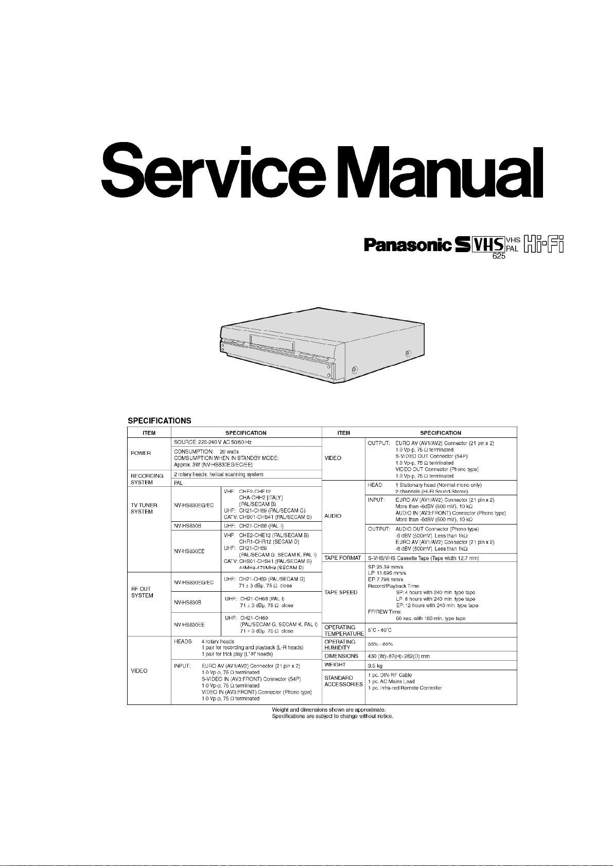
Panasonic NV-HS830EG User manual
Other Panasonic VCR System manuals

Panasonic
Panasonic AG-W3 User manual

Panasonic
Panasonic PV-VS4821-K User manual

Panasonic
Panasonic NV-HV61EB User manual

Panasonic
Panasonic Omnivision PV-4652 User manual

Panasonic
Panasonic OmniVision PV-QV200 User manual

Panasonic
Panasonic PV-455S-K User manual

Panasonic
Panasonic ProLine AG-1980P User manual

Panasonic
Panasonic Omnivision VHS PV-7664 User manual

Panasonic
Panasonic NV-SD440EG/ User manual

Panasonic
Panasonic AG3200 User manual

Panasonic
Panasonic NV-SV120EC User manual

Panasonic
Panasonic NV-FJ603EL-K User manual

Panasonic
Panasonic Quasar Omnivision PV-V4021-K User manual

Panasonic
Panasonic AG-DV1DC P User manual

Panasonic
Panasonic NV-SD250 Series User manual

Panasonic
Panasonic Quasar PVQ-1310 User manual

Panasonic
Panasonic Omnivision PV-8200 User manual

Panasonic
Panasonic PV-C2022-K User manual

Panasonic
Panasonic Omnivision PV-7665S User manual

Panasonic
Panasonic NV-HD650 Series User manual