manuals.online logo
Brands
  1. Home
  2. •
  3. Brands
  4. •
  5. Panasonic
  6. •
  7. VCR System
  8. •
  9. Panasonic Omnivision PV-7664 User manual

Panasonic Omnivision PV-7664 User manual

Th^mfc ymi fbr ehao&ing
Panasonic
Omnivlslan
MODEL PV-7664
Video 0a8$9tte Recorder
Eaty Taping.
Operating
Instructions
Please raad thes^ instri^ctions carcfuEl]^ bfifore
cocwiect. ope rata or 3d>uBt this product Please
Things You Should Know
rDate of Purchase
PV-7664
Congratulations
on your purchase of one of the most sophisticated and
reliable products on the market today. Used properly,
it will bring you and your family years of enjoyment.
Please fill in the information at right. The serial number
is on the tag located on the back of your VCR.
Safety Precautions
Warning: To prevent fire or shock hazard, do not expose this equipment to rain or moisture.
This video recorder, equipped with the HQ {High Quality) System, is compatible with existing VMS equipment.
Only use those tapes with the IVHSI mark. It is recommended that only cassette tapes that nave been tested
and inspected for use in 2, 4, 6, and 8hour VCR machines be used.
Dealer Purchased From
Dealer Address
Dealer Phone No.
Model No
Serial No
FCC Warning: Any unauthorized changes or modifications to this equipment would void the user's authority to operate.
rACAUTION
KOF EUCTWC SMOCKl A
CALTDOH TO REDUCE ThiE RISK OF ELECTRIC SHOCK.
OOt<IOT REMOVE COVER |0R BACK;
NO MSEA SEnviCEABlE PARTS INSJOE
REFER tERVICINQ TO QLMUFIED SERVICE PERSONNeL
This symbol warns the user that uninsulated voltage within the unit may
have sufficient magnitude to cause electric shock. Therefore, it is
dangerous to make any kind of contact with any inside part of this unit.
This symbol alerts the user that important literature concerning the
operation and maintenance of this unit has been included.
Therefore, it should be read carefully in order to avoid any problems.
Table of Contents
Important Safeguards and Precautions 3
Unpacking Your VCR •Product Features ;4
VCR and Cassette Information (Record Tab, Tape Speeds, Head Cleaning, D.S.T., Specifications) 5
Basic Connection (Antenna and VCR, VCR and TV) 6, 7
Additional Connections (CATV, AudioA/ideo) 8, 9
Location of Controls (Remote Control, VCR) 10,11
One Time VCR Setup
(On-Screen Language, Cable Box/ DSS Receiver Setup, Channel Memory, Auto Clock Set) 12^1
7
On-Screen Displays (OSD) (Function. Channel. Menu. VCR Status &Clock. Warning) 1
8
Playback aTape (Main Operation. Special Effects, Quality Picture Features) 1
9
Record On aTape (Main Operation, One Touch Record, Channel Selection) 20
Copying Your Tapes (Dubbing) (Connection, Main Operation, Monitoring, Select Input Mode) 21
Timer Recording (Main operation, Cancel. Clear or Replace Program Contents) 22, 23
Tape Operation (Commercial Advance,
Repeat Play. Zero Search, Shuttle Search, Auto Functions. Index Search) 24-^30
Special VCR Features (VCR Lock, Warning Beeper) 31
MTS Broadcast/ VMS Hi-Fi Stereo System (Stereo/SAP/Mono Broadcast, Select Audio Mode, Spatlalizer) ... 32, 33
VCR Plus+ Setup (VCR PIUS+ Channel Setup) 34
VCR Plus+ Programming (Main operation, Make Correction) 35
Multi-Brand Control Feature 36, 37
Before Requesting Service (Self-check items) 38
Service Center List 39
Warranty 40
Spanish Quick Use Guide 41 -43
Quick Use Guide Back Cover
2
Jl^Important Safeguards and Precautions
FOR YOUR SAFETY, READ AND RETAIN ALL
SAFETY AND OPERATING INSTRUCTIONS.
HEED ALL WARNINGS IN THE MANUAL AND
ON THE UNIT
OUTDOOR ANTENNA INSTALLATION
INSTALLATION
1POWER SOURCE CAUTION
Operate only from apower source indicated on the
unit or in this manual.
If necessary, have your Electric Utility Sen^ice Company
or Video Products Dealer verify the power source in your
home.
2POLARIZED OR GROUNDING PLUG
As asafety feature, this Video product comes with either
apolarized power cord plug (one blade is wider than the
other), or athree-wire grounding type plug.
POLARIZED PLUG CAUTION:
This plug will only fit into an outlet one way. If you cannot
fully insert the plug, try reversing it. If it still will not fit, have
an electrician install the proper wall outlet. Do nol defeat the
safety feature by tampering with the plug.
GROUNDING PLUG CAUTION:
This plug will only fit into athree-hole grounding outlet. If
necessary, have an electrician install the proper outlet. Do
not defeat the safety feature by tampering with the plug.
3POWER CORD
Make sure power cords are routed so that they are not
likely to have anything rest on them, roll over them, or be
in the way of walking traffic.
If an extension cord is used, make sure it also has either
apolarized or grounded plug and that the cords can be
securely connected.
Frayed cords, damaged plugs, and damaged or cracked
wire insulation are hazardous and should be replaced by
aqualified service technician.
Overloaded outlets and extension cords are fire hazards
and should t>e avoided.
4DO NOT BLOCK VENTILATION HOLES
Ventilation openings in the cat^net release heat
generated during (^ration. If they are blocked, heat
build-up inside the unit can cause faPures that may result
in afire hazard or heat damage to cassettes.
For protection, follow these rules:
a. Never cover ventilation slots or tiie unit while in use,
or operate the unit when placed on a bed. sofa, rug, or
other soft surface.
b. Avoid built-in installation, such as abookcase or rack,
unless proper ventilation is provided.
5AVOID EXTREMELY HOT LOCATIONS OR
SUDDEN TEMPERATURE CHANGES
Do not place the unit over or near any kind of heater or
regulator, in direct sunlight, inside aclosed vehicle, etc..
Do not move the unit suddenly between areas of
extreme temperature variation. If the unit is suddenly
moved from acold place to awarm place, moisture
may condense in the unit and on the tape.
6TO AVOID PERSONAL INJURY
>Do not place ur^cured equipment on asloping
surface.
•Support for the urdt should be firm,
level, and adequately strong.
•An appliance and cart combination
should be moved with care.
Quick stops, excessive force,
and uneven surfaces may cause
the appliance and cart combination
to overturn.
•Carefully follow all operating instructions and use
the manufacturer's recommended accessories
when operating this unit or connecting it to any
other equipment
ANTENNA
lEAOtt
WMC
AHIEHNA
DrSCHtRGE UNIT
(NEC SECTION ilO-20)
SAFE ANTENNA AND CABLE CONNECTION
If an outside antenna or cable
system is connected to the
equipment, be sure the antenna
or cable system is grounded so
as to provide some protection
against built up static charges
and voltage surges. Section
810 of the National Electrical
Code. ANSI/NFPA 70 (in Canada,
part 1of the Canadian Electrical
Code) provides information with
respect to proper grounding of the
mast and supporting structure, grounding
of the lead-in wire to an antenna discharge unit,
size of grounding conductors, location of antenna
discharge unit, connection to grounding electrodes
and requirements for the grounding electrode.
KEEP ANTENNA CLEAR OF HIGH VOLTAGE
POWER LINES OR CIRCUITS
An outside antenna system should be located well away from power lines,
electric light or power circuits and where it will never come into contact with
these power sources if it should happen to fall. When installing an outside
antenna, extreme care should be taken to avoid touching power lines,
circuits or other power sources as this could be fatal. Because of the
hazards involved, antenna installation should be left to aprofessional.
USING THE VIDEO UNIT
If the unit has been in storage or moved to anew location, refer first
to the INSTALLATION section of these safeguards.
1KEEP THIS VIDEO UNIT AWAY FROM WATER OR
MOISTURE OF ANY KIND.
2IF EQUIPMENT IS EXPOSED TO RAIN, MOISTURE, OR
STRONG IMPACT, unplug the unit and have it inspected by aqualified
service technician before use.
3DURING AN ELECTRICAL STORM
During alightning storm, whether indoors or outdoors, or before leaving the
unit unused for extended periods of time, disconnect all equipment from the
power source as well as the antenna and cable system.
4WHEN THE UNIT IS PLUGGED IN
•Never expose the unit to rain or water. DO NOT OPERATE if liquid has
been sptfied into the unit. Immediately unplug the unit, and have it
inspected by aservice technician. Fire and shock hazards can result from
electrical shorts caused by liquid contact inside.
•Never drop or push any object through openings in the unit. Some internal
parts carry hazardous voltages and contact can cause electric shock or fire
hazard.
•Avoid placing the unit directly above or below your TV set as this may
cause electrical interference. Keep all magnets away from electronic
equipment.
5USING ACCESSORIES
Use only accessories recommended by the manufacturer to avoid risk of fire,
shock, or other hazards.
6CLEANING THE UNIT
Unplug the unit. Then, use aclean, dry. chemically untreated cloth to gently
remove dust or debris. DO NOT USE cleaning fluids, aerosols, or forced air
that could over-spray, or seep into the unit and cause electrical shock.
Any substance such as wax, adhesive tape. etc. may mar the cabinet surface.
Exposure to greasy, humid, or dusty areas may adversely affect internal parts.
SERVICE
DO NOT SERVICE THIS PRODUCT YOURSELF
If, after carefully following the detailed operating Instructions, this Video
product does not operate properly, do not attempt to open or remove covers,
or make any adjustments not described in the manual. Unplug the unit and
contact aqualified service technician,
IF REPLACEMENT PARTS ARE REQUIRED
Make sure the service technician uses only parts specified by the manufacturer,
or those having the same safety characteristics as the original parts. The use of
unauthorized substitutes may result in fire, electric shock, or other hazards.
HAVE THE SERVICE TECHNICIAN PERFORM
ASAFETY CHECK
After any service or repairs to the unit, request the service technician to
conduct athorough safety check as described in the manufacture's sen/ice
literature to insure that the video unit is in safe operating condition.
3
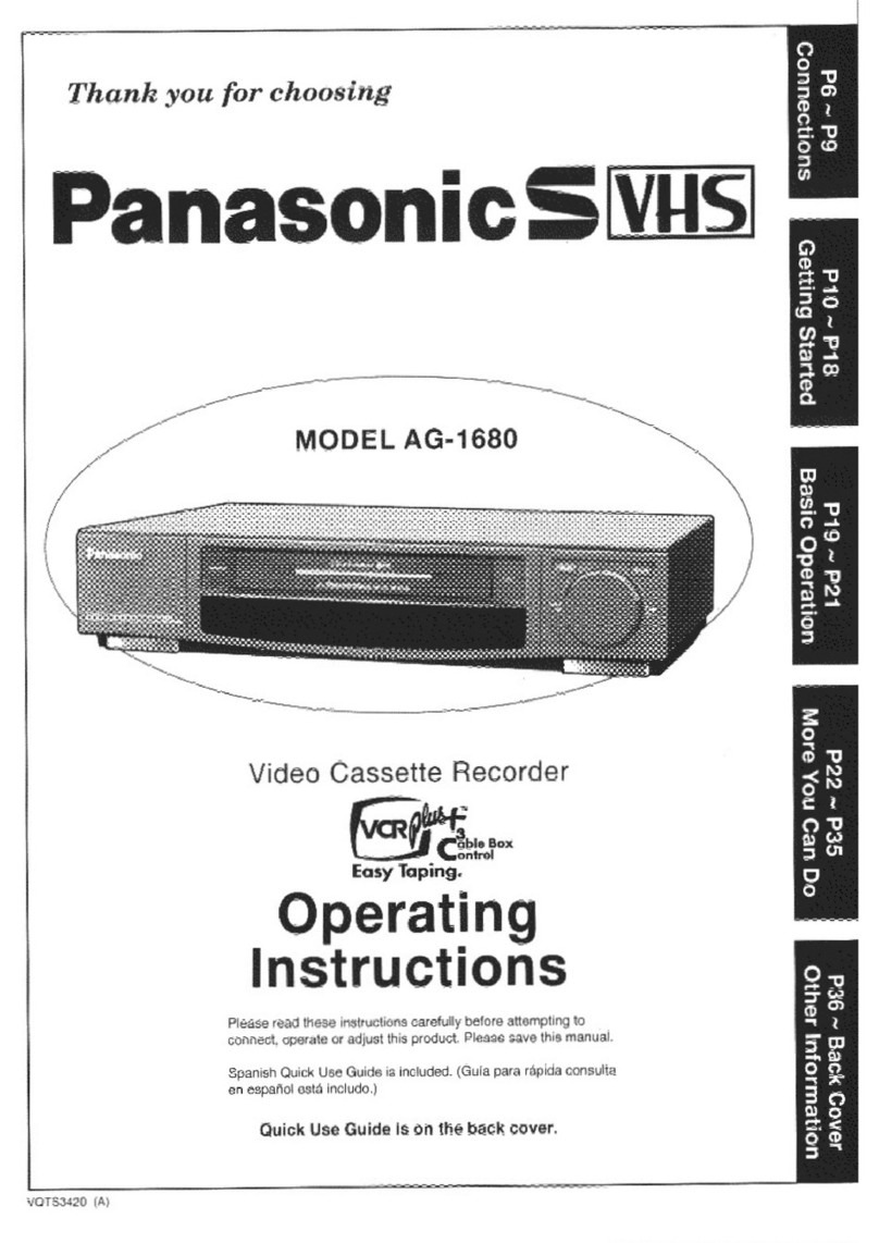
Your VCR •Product Features
Unpacking Your VCR
The accessories below are provided to help
you use or set up your VCR.
Accessories
00®
©0®
e©©
Remote Control
VSQS1498
0) )
)
<t>) )
3"AAA"
Batteries
RF Coaxial
Cable
VJAS0183
To order accessories,
call toll free 1-800-332-5368.
Loading the Batteries
Push in and up on
the latch with your
thumb nail and lift off
the lid.
Install three batteries
as indicated inside the
Battery Compartment.
Fit the lid's hinge
piece into the indent
on the case, and snap
the lid into place.
Battery replacement caution
•Do not mix old and new batteries.
•Do not mix alkaline with manganese batteries.
Product Features
Advanced Noise Reduction 19
All Channel Auto Set/ 181-CH TV/CATV Tuner 14, 15. 16
Auto Clock Set 14, 15, 16
Auto Daylight Saving Time 5
Auto Features for aQuality Picture 19
Auto Operation Functions (Auto Playback, Rewind, Tape Eject, Power off) 29
Auto Repeat Function 28
Cable Box Cliannel Control 13
Color Noise Reduction 19
Commercial Advance 24-27
Digital Auto Picture 19
DynAmorphous™ Metal Head 19
Easy-to-Read English/Spanish/French On-Screen Displays 14-17, 22, 23
Front-mounted N\l In Terminals 21
Head Cleaner 5
MTS Broadcast System (Multi-channel Television Sound-Stereo, SAP, Mono) 32
Multi Brand TV/Cable Box Remote Control 36, 37
One Month, 8Program Timer Recording 22, 23
One Touch Recording (OTR) 20
Program Director Remote Control 22, 23
Shuttle Search 29
Spatializer 33
Special Effects Playback 1
9
Special VCR Features (VCR Lock, Warning Beeper) 31
VCR PIUS+ Recording 34, 35
VHS Hi-Fi Stereo System 33
VHS Index Search System (Direct Access Search, Index Scan Search) 30
Zero Search 28
4
VCR and Cassette Information
Erase Protection (Record Tab)
Cassettes have arecord tab to ensure that
recordings are not accidentally erased.
To prevent accidental
erasure, break off the tab
with ascrewdriver^ l—
To record again, cover the
hole with cellophane tape.
Reset all VCR Memory Functions
Use when moving the VCR to anew location, or if amistake
was made in the One Time VCR Setup section.
•Make sure atape is not inserted in the VCR.
1) Turn VCR Power on.
2) Push and hold both PLAY and CHANNEL Aon the VCR
for more than 5seconds.
*The power will shut off.
3) Perform the One Time VCR Setup section on page 14.
Maximum Record/Playback Time
Only use tapes with the IVHSI mark in this uni
Tape Speed
Setting
Type of Video Cassette
T60 T120 1160
SP
(Standard Play) 1Hour 2Hours 2Hours
40 Minutes
LP
(Long Play) 2Hours 4Hours 5Hours
20 Minutes
SLP
(Super Long Play) 3Hours 6Hours 8Hours
Build-in Head Cleaner
Aclean video head helps produce aclear picture.
So, we have equipped your VCR with abuilt-in, non
chemical head cleaning system that helps prevent
clogging of the video heads. Cleaning is performed
each time you load or unload avideo cassette.
Note: This feature is preventative only. If your video
heads are seriously clogged, consider the use of
achemical nonabrasive liead cleaning kit or take
your VCR to aService Center.
Head Cleaning
Your VCR will not normally require head cleaning,
however the heads may become clogged when playing
an old or damaged tape.
Video Heads Sensor System
If head cleaning becomes
necessary, the VCR will
display the screen at right
while playing back a
recorded signal.
To exit this screen, push PLAY
on the remote control or VCR.
VIDEO HEADS MAY
NEED CLEANING
PLEASE INSERT HEAD
CLEANING CASSETTE
OR REFER TO MANUAL
END: PLAY KEY
•Use "dry" type head
cleaning cassette* only.
•Be sure to follow the cleaning tape Instructions
carefully. Excessive use of acleaning cassette can
shorten head life.
•If using ahead cleaning cassette does not solve the
problem, contact your nearest Factory Service Center
or authorized Service Center.
•Cleaning cassette part No. NV-TCL30PT is
recommended.
D.S.T. (Daylight Saving Time)
Spring (First Sunday in April)
When the VCR is set to DST:ON, it automatically adds
one hour and adjusts the clock.
NORMAL TIME 1:00 a.m. 2:00 a.m.
DAYLIGHT
SAVING TIME 3:00 a.m. 4:00 a.m.
Autumn (Last Sunday in October)
When the VCR is set to DST:ON, it automatically turns back
one hour and adjusts the clock.
DAYLIGHT
SAVING TIME
1:00 a.m. 2:00 a.m.
NORMAL TIME 1:00 a.m. 2:00 a.m.
Specifications
Power Source:
Power Consumption:
Video Signal:
Video Recording System
Audio Track:
Tuner:
Broadcast Clianneis:
CATV Channels:
Operating Temperature:
Operating hiumidlty:
Weigiit:
Dimensions:
120V AC, 60 Hz
Approx. 23 watts (Power on)
Approx. 7 watts (Power off)
EIA Standard NTSC color
4rotary heads helical
scanning system
1track (Normal)
2channel (Hi-Fi Audio Sound)
VHP 2-13, UHF 14-69
MIdband Athrough I(14-22)
Superband Jthrough W(23-36)
Hyperband AA-EEE (37-64)
Lowband A-5-A-1 (95-99)
Special CATV channel 5A (01)
Ultraband 65-94, 100-125
4rF-104*'F (5''C~40°C)
10%~75%
7.7 lbs. (3.5 kg)
16-15/16" (W) X3-7/8" (H) X
11-13/16" (D)
430 (W) X98 (H) X300 (D) mm
Note: Designs and specifications are subject to change
without notice.
Basic Connection
Connect the VCR to your TV
with the RF Coaxial Cable (OUT TO TV).
rWARNING
IWhen using "Nut type" RF coaxial cables, tighten with fingers only. Overtightening may damage terminals.
Between Antenna and VCR Between VCR and TV
Case 1:Twin Lead Cable Only
(Flat) Twin Lead 300
Ohm Cable
To VCR Terminal
300-75 ohm Transformer
(not supplied)
Case 1:Screw &Plug Type Terminal
UHF/VHF Band Separator
(not supplied}
RF Coaxial Gable
VHF
UHF
Case 2: Twin Lead &Coaxial Cables
(Round) 75 Ohm
coaxial Cable
UHF/VHF
Band Mixer
(not supplied)
To VCR Terminal
Case 3: Two Twin Lead Cables
300-75 ohm Transformer
(not supplied)
UHF/VHF
Band Mixer
(not supplied)
To VCR Terminal
If your TV has both post and plug-type VHF
terminals, the post connection is recommended
to minimize signal loss.
Case 2: Screw Type Terminal
TV
75-300 ohm Transformer
(not supplied)
Case 3: Double Screw Type Terminal
TV
UHF/VHF Band Separator
(not supplied) VHF
UHF
Case 4: Complex TV Terminal
TERMINALS ON BACK OF TV SET
ANT2
Connect to one of the ANT terminals and select
the same antenna number on the TV.
7
Additional Connections
CATV(Cable) Connections All connections on this page are made with 75 Ohm coaxial cables.
Without aConverter/Descrambler Box
You can:
1)Use your VCR Remote Control to select channels.
2) Program one or more unscrambled channels for
unattended recording.
You cannot:
record or view scrambled channels
with this connection.
VCR IN FROM ANT.
IN FROM
CABLE
With a(CABLE to VCR) Converter/Descrambler Box
You can:
1) Record and view any channel including
scrambled channels; channel selection
must be made at the Cable TV Converter
Box,
2) Program one channel for unattended
recording.
You cannot:
select channels from VCR or TV.
Cable TV Converter
Box
OUT TO TV
IN FROM
CABLE
VHF/UHF
With a(VCR to TV) Converter/Descrambler Box
You can:
1)Use your VCR Remote Control to select channels.
2) Program unattended recordings of more than
one unscrambled channel.
You cannot:
record scrambled channels with this connection. Cable TV
Converter
Box OUT VHF/UHF
With Two Converter/Descrambler Boxes
If you want to record and view
acombination of scrambled
and unscrambled channels,
you will need additional
equipment.
This connection requires
two converter boxes,
an A/B switch, and
a2-way splitter
as shown here.
IN FROM
CABLE 2-Way
1,^ VSplitter
Converter Box 1
OUT A/B Switch
OUT TO TV
8
With aDSS Receiver
You can:
1) Record and view any channel including
scrambled channels; channel selection
must be made at the DSS Receiver.
2) Program one channel for unattended
recording.
NOTE: The DSS receiver must be turned
off to view programs from acable
box or antenna. See the DSS
manual for details.
IN FROM
CABLE or
Antenna IN FROM
Satellite Dish OUT TO TV
VHF/UHF
'DSS® is aregistered trademark of DIRECTV, INC., aunit of GM Hughed Electronics.
Audio/Video Connections
If your TV has AUDIO IN and VIDEO IN terminals, you can connect your
VCR to them to receive ahigher quality picture and sound. If your TV is not
stereo, you can connect astereo amplifier to the VCR to enjoy stereo sound.
IN FROM ANT
OUT TO TV
1Connect the VIDEO OUT tenninal on the VCR to the VIDEO IN terminal of your TV.
2Connect the "L" and "R" AUDIO OUT terminals on the VCR to the "L" and "R" AUDIO IN terminals of your TV.
3Set the VIDEO/TV selector of your TV (Monitor/Receiver) to "VIDEO."
NOTE: To use your TV as aVCR monitor, set the VIDEO/TV selector on the TV (Monitor/Receiver) to "VIDEO."
Use the LAudio In jack for proper sound reproduction when connecting to amonaural TV.
Stereo Amplifier Connections
When you connect your VCR to a
Stereo Component System, you
can view the picture from the VCR
while enjoying stereo from your
audio system.
Connect the "L" and "R" AUDIO
OUT terminals on the VCR to the
"L" and "R" AUDIO IN terminals of
your stereo.
Stereo Amplifier VCR
Note to CATV system installer:
This reminder is provided to call the CATV system installer's attention to Article 820-40 of the NEC in USA (and to the
Canadian Electrical Code in Canada) that provides guidelines for proper grounding and, in particular, specifies that the cable
ground shall be connected to the grounding system of the building, as close to the point of cable entry as practical.
9
Location of Controls
Remote Control Buttons
VCR
See pages 36. 37
VCR/TV
See pages 14. 20
PLAY
See pages 19, 25, 26, 30
SELECT UP
See pages 14-18, 22-26, 28, 31, 33, 34, 35
FAST FORWARD/SEARCH
See pages 19,26. 30.
SET
See pages 14-18, 22-26, 28, 31. 33. 34, 35.
STOP
See pages 17, 19, 20, 23, 25, 30,
SELECT DOWN
See pages 14-18, 22-26, 28, 31, 33, 34, 35.
MENU
See pages 15-18. 24-26. 28. 31 .33. 34.
COMMERCIAL ADVANCE/
ZERO SEARCH
See pages 26, 28.
NUMBERED KEYS
See pages 17, 20, 24. 30, 35-37
SPEED
RECORD/TIME
See page 20.
SLOW
See page 19.
CHANNEL UP/DOWN
(TRACKING UP/DOWN)
See pages 14-17, 19-21.
VOLUME UP/DOWN
See page 37.
DISPLAY/ENTER
See pages 20. 35 See pages 18, 20. 28. 32, 37.
COUNTER RESET
See page 28. ADD/DELETE
See pages 16, 17, 23, 34. 35.
INDEX
See page 30.
SHUTTLE Ring
See page 29.
Front View of the VCR
VCR/TV Selector
See pages 14, 20,21.
POWER
See pages
CHANNEL UP/DOWN
TRACKING/V-LOCK
Seepages 14-17, 19-21.
14. 22. 23. 35
VIDEO Input
Connector
See page 21.
STOP
Cassette Compartment See pages
See pages 19, 20. 21 ,25. \9, 20, 21 .23, 25, 30, 31
.
PLAY
See pages
19,21,25. 26. 30.
AUDIO Input
Connector (L/R)
See page 21. REMOTE
SENSOR
SHUTTLE Ring
(For Fast Forward
or Rewind Search)
See pages
19, 26,29. 30.
RECORD/TIME
Seepages 20,21.
10
Multi Function Display
Speed Indicator
Record Indicator
See page 20.
Power Indicator
Cassette-In
Indicator
Hi-FI Indicator
See page 33.
Rec Level Meter
See page 33.
Timer Indicator
See pages 20. 22, 23, 35.
SAP STEFteO
mAM
PM
SAP Indicator
See page 32.
Stereo Indicator
See page 32.
Function Indicators
See below.
Clock/Status/Channel Display
VCR Indicator
See pages 19, 20.
Play/ Slow/ rv.
Frame i.>
Advance ''*'
Reverse Play .^-j
(Slow/ Frame <:
Advance)
Rewind/ s
Rewind -<
Search! ^
Fast Forward/ /
Fast Forward -i**>-
Search /'- j' ^
Record r*.. IIIS Record/ r:
Pause r: tsiga Still Eject
Rear View of the VCR
AC Power Plug
While plugged into an AC outlet,
the VCR consumes 7Wof
electrical power In OFF condition.
Audio Output
Connector (UR)
See pages 9. 21, 32.
Video Output Connector
See pages 9. 21 .32.
VHF/UHF Antenna
Input Terminal
See pages
6-9, 12. 32.
Audio Input Connector (L/R)
See pages 12, 21.
'^^^^ VHF/UHF Antenna
Output Terminal
See pages
Channel 3/4 Switch 6-9, 12, 21, 32.
See pages 6, 14.
Video Input Connector
See pages 12, 21.
11
One Time VCR Setup
The setup on pages 14 through 16 is vital for proper VCR operation.
Please read the Instructions carefully and in the order presented.
NOTE: These first two pages contain reference material needed for setup on pages 14-16.
Please look over the information before you begin setup procedure.
Setup Overview
You will be performing the following tasks:
•Setting the language you want on-screen displays to appear in (English, Spanish, French).
•Telling the VCR what kind of equipment you are using to receive channels and how it is connected.
•Entering pertinent cable box or DSS receiver information if used.
•Entering alocal PBS channel so that the VCR can receive auto clock set data. (Not available in all areas.)
•Placing channels in memory and setting the clock.
Please Note Which Connection Type You are Using,
Make sure all equipment is hooked up as described on pages 6-9.
The diagrams below illustrate some of the basic connection types.
Confirm which type you used for later reference.
Connection Type 1
A.<CABLE BOX ->VCR ->TV>
From Cable Back of VCR
^
Cable Box "
RF Coaxial
Cable
H.AUOmi-L VIDEO »Kr
®<3 ®z:
Cable/ ii "'^ 9<'"'!iJ!LSf"»
IAntenna i
Back of jS/"'-"'"-
(supplied)
B.<ANT/CABLE BOX ->DSS BOX *>VCR ->TV>
Back of VCR
iCabte/
RFCoaxial ;Antenna
(supplied)
Back of TV
Connection Type 2
C.<VCR ->TV>
From Antenna
or Cable
Back of VCR
D.<VCR ->CABLE BOX ->TV>
Back of VCR
From Antenna
or Cable
Back of TV
Back of TV
Cable/ i
Antenna;
RF Coaxial Cable
(supplied)
Cable Box
ONE TIIME SETUP ilMPORTANT NOTES:
•For detailed DSS receiver connection instruction, please see your DSS operating manual.
•The DSS receiver must be turned off to view programs from the cable box or antenna.
•If you use aDSS receiver, it must be turned off for auto clock set.
•If your cable box is not remote controllable, it must be tuned to your PBS channel.
•If you use Audio/Video Jack connection between the VCR and cable box or DSS receiver, you must also
connect the RF coaxial cable In order to use the auto clock set and channel auto set features.
12
Cable Box/ DSS Receiver Code Number List
If your cable box or DSS receiver is remote controllable, refer to this list during setup on page 14.
Cable Box
Brand Code Numbers
Archer 01,29,44, 88.91
Cabteview 30, 42, 44, 52, 63, 88
Citizen 30,42, 44, 52,63,88
Curtis 08, 09.56,61,87, 90
Diamond 01 ,29, 44, 88, 91
Dral<e 37, 67, 71
Eagle 13, 20, 22, 26, 40, 58, 62
Eastern 28
GC Brand 30, 42, 44, 52, 63, 88
Gemini 04, 85
General Electric 57
General Instruments
01 ,02, 03, 04, 34, 55, 83, 85. 91 ,93, 95
Hamlin 14, 15, 28. 41
Hitachi 31,79
Jerrold .... 01 ,02, 03, 04, 34, 55, 83. 85, 91 .93, 95
Macom 31, 79
Magnavox 25, 26
Movietime 29, 32, 38, 39, 40, 42, 44, 88
NSC 32, 38, 40
Oak 11,46
Panasonic 16, 17
Philips 13. 20, 23, 24, 96
Pioneer 05, 06,78
Pulsar 30,42.44, 52,63, 88
RCA 16, 17
Realistic 44, 51,88
Regal 14, 41
Regency 28
Code Numbers
Rembran 29. 32, 39, 42, 44. 88
Salora 68, 72
Samsung 32, 40, 42, 78, 94
Scientific Atlantic 08, 09, 56, 61 ,87, 90
Sheritech 27
SL Marx 32, 40. 42, 78, 94
Spucer 16, 17
Stargate 30, 32, 40, 42, 44, 52, 63, 78, 88. 94
Sylvania 19
Telecaption 77, 92
Teknil<a 74
Teleview 32, 40, 42. 78, 94
Texscan 18, 19
Tocom 01 ,33, 34, 42, 48, 49, 91
Toshiba 36
Uniden Satellite 65, 69
Unlka 01 .29, 44, 88. 91
Universal 42, 43, 44, 52, 63, 88
Viewstar 13. 20. 22, 26. 40. 58, 62
Vid Tech 64
VIdter 64
Videoway 07, 23, 50
Zenith 07, 23, 50
DSS (Digital Satellite System Receiver)
Sony 98
RCA 99
Panasonic 100
Note: During setup you will be instructed to enter your brand code number. As some brands have
multiple codes, it may be necessary to try different codes to attain the proper results.
These codes are for Cable box or DSS Box setup for Auto Clock and VCR Plus+ recording only.
For TV/Cable Box Multi-Brand Control operation, please see page 34.
Positioning Your Cable Box or DSS Receiver
if your cable box or DSS receiver is renfiote controllable, place it on or near the VCR as shown
in the example below. The VCR transmits an infrared signal from two locations. Be sure not to
cover the transmitter windows.
Wall
VCR's signal
Transmitters
I
13
One Time VCR Setup (continued)
When the VCR power is first turned on, the
language select screen appears automatically.
Follow along in the manual as you guided are
through the setup procedure on the screen.
[N^Check list before you begin.
QAll TV and VCR connections are made.
(See pages G'-S.)
MENU o©©
0©©^
0® ©
__Mioa.\
©©©0
Using AT 4keys
Whenever amenu or
program screen is displayed, ^
the PLAY. STOP, REWIND,
and FF buttons on the remote
control function as AT only.
For play, stop, rewind, and fast forward
functions, use the buttons on the VCR.
On Screen Language, Cable/ DSS
Receiver Setup, Channels Memory,
and Auto Clock
Turn TV and VCR on.
Tune TV to VCR output channel {the same one
you set on the back of the VCR: CHS or CH4).
or
yor
VCR/TV
Push CH for
English on-screen
displays.
Push CH for
Spanish on-screen
displays.
Push VCR/TV for
French on-screen
displays.
SELECT LANGUAGE
PUSH VCn CH a: ENGLISH
PULSE VCR CH ESPANOL
APP. VCR/ TV ;FRANQAIS
If wrong language
is set, see the
"Reset all VCR
Memory Functions"
section on page 5.
You can also set the language using the buttons on the VCR.
The VCR should be connected to an antenna or
cable box (page 6'-9).
Push AT to select
your hookup, and
then push to set.
(Refer to page 12.)
•If you selected CABLE/
DSS BOX^VCR^TV,
continue with step 5.
If not, go to Alternate
Instructions on page 16.
SELECT HOOKUP
ABLE/DSS BOX^VCRMV
VCF>CABLE/DSS BOXMV
VCR>-TV
SELECT:
SET
END
AtKEY
KEY
MENU KEY
•4 too)
Push AT to select
your cable box or
DSS receiver output
channel number, and
then push to enter.
•If necessary, refer to your
cable box manual.
•If both acable box and DSS receiver are used,
set the output channel of the DSS receiver.
•If you are using AudioA/ldeo jack connections
to your cable box, select and set "VIDEO OUT
as the output channel.
SELECT HOOKUP
CABLE/OSS 0OX»VCf>1V
CABLE /DSS BOX OUTPUT CH
SELECT:AKEY
SET KEY
END :MENU KEY
ENTER CODE NUMBER
REFERRING TO MANUAL
Push AT to select
your cable box or DSS
receiver code number,
and then push to
enter. (Refer to the list
on page 13.)
•If your cable box or DSS receiver doesn't
have aremote control, select "NO REMOTE."
Then, go to Alternate Instructions on page 16.
•This determines whether the VCR will control
your cable box or DSS receiver.
SELECT:* TKEY
SET KEY
END :MENU KEY
14
If you use acable box,
tune it to channel 02.
If you use aDSS receiver,
tune it to channel 270.
APush to continue.
•"NOW TRANSMITTING"
appears.
If Cable Box
PLEASE TUNE YOUR CABLE
BOX TO CH02.
If DSS Receiver
P[
B
PLEASE TUNE YOUR OSS
RECEIVER TO CH 270.
PROCEED KEY
END :MENU KEY
Push AT to select
"YES" or "NO," and
then push to enter.
If Cable Box
IS YOUR CABLE BOX
RECEIVING CH 09 ?
NO
If DSS Receiver
IS YOUR OSS RECEIVER
RECEIVING CH 200?
NO
SELECT: ATKEY
SET >KEY
END :MENU KEY
If you use acable box
and selected "YES,"
go to step 9.
If you use aDSS receiver
and selected "YES," go to
the Alternate Instructions
on page 16.
If you selected "NO,"
the screen in step 6on
page 14 will reappear.
Try entering adifferent code
assigned to your brand and/ or repositioning
the equipment (see page 13).
If the answer is still "NO." cable box or DSS
receiver control is not available.
Push MENU and go to the Alternate
Instructions on page 16,
Confirm that your cable box is on and
that your DSS receiver is off.
Push AT to select
your local PBS channel
number you receive on
your cable box, and
then push to display
the "CLOCK AUTO
SET" screen.
PLEASE ENTER YOUR LOCAL
PBS CHANNEL ON CABLE BOX
SELECT:* KEY
SET >KEY
END :MENIU KEY
CH Push CH to start
Auto Clock Set.
•If you live near adifferent time
zone, be sure to enter the PBS
channel in your time zone.
•"AUTO CLOCK SET
PROCEEDING" appears.
CLOCK AUTO SET
CONNECT ANTENNA CABLE
AND IF YOU USE ACABLE
BOX. TUNE IT TO YOUR
LOCAL PBS CH THEN. ..
PLEASE PUSH CH UP KEY
If the Auto Clock Set
displayed time is incorrect.
If you use acable box and
receive more than one PBS
station, try auto clock set again.
Follow the Set or Reset Auto
Clock Set section on page 1
7
and when the instructions call for
you to enter aPBS station, enter
the one you have not tried yet.
If "AUTO CLOCK SET IS
INCOMPLETE" appears...
The screen below will appear
on-screen if auto clock set data
is not available in your area.
AUTO CLOCK SET
IS INCOMPLETE
PUSH MENU TO SET CLOCK
Push MENU to display the
manual clock set screen.
(See the Manual Clock Set
section on page 16.)
Note:
If you use acable box and
receive more than one PBS
station, you may exit the manual
clock set screen and try auto
clock set again.
Follow the Set or Reset Auto
Clock Set section on page 17and
when the instructions call for you
to enter aPBS station, enter the
one you have not tried yet.
CM This display appears when
auto clock set is completed.
Confirm that the time is
correct and push CH A
to exit.
7/25/1997 FRI 12:00PM
DST:ON
SETTING :CH02
AUTO CLOCK SET
COMPLETED
END :PUSH CH UP KEY
Auto clock set will be performed when the VCR is turned off the first time each day. If you use a cable
box and you want auto clock set to be performed, the cable box must be left on and tuned to the PBS
channel before the VCR power is turned off.
15
One Time VCR Setup (continued)
Alternate Instructibns
Complete the following steps if, any of the following
applies:
AYou selected connection type 2(VCR^CABLE/
DSS BOX^TV or VCR^TV) in step 4on page 14.
BYou selected "NO REMOTE" in step 6on page 14
(your cable box or DSS receiver is not remote
controllable).
CYou use a DSS receiver and selected "YES" in
step 8on page 15.
DCable Box or DSS receiver could not be controlled
in step 8on page 15.
®Turn on the cable box and set
it to the local PBS channel.
•If you live near adifferent time
zone, make sure to set the
channel in your time zone.
•If you use aDSS receiver,
It must be turned off.
CHANNEL/CLOCK AUTO SET
CONNECT ANTENNA CABLE
AND IF YOU USE ACABLE
BOX, TUNE ITTO YOUR
LOCAL PBS CH THEN. .
.
PLEASE PUSH CH UP KEV
CH Push CH Ato start Channel
Auto Set and Auto Clock Set.
•The following messages appear.
"CH AUTO SET PROCEEDING"
"AUTO CLOCK SET PROCEEDING'
fr
STOP
MENU
NUMBERED
keys
100 key
^515* WTV CATV
GOB
--
^©0
©I® u
3©©
SELECT/SET
keys
CHANNEL UP
ADO/DELETE
This screen appears to confirm
that auto clock set is completed.
Confirm that the
time is correct and
push CH to exit
this screen.
If this screen appears,
auto clock set is not
available in your area.
Please set the clock
manually as described
at right.
7/25/1997 FRl \2m
OST:ON
SETTING :CH02
AUTO CLOCK SET
COMPLETED
END :PUSH CH UP KEY
AUTO CLOCK SET
tS fNCOMPLETE
PUSH MENU TO SET CLOCK
If the displayed auto clock set time and
D.S.T. are not correct
If you live close to two different time zones, the VCR may
recognize the wrong PBS station as the setting channel.
If this happens, please complete the following steps.
1Make anote of the SETTING: CH number shown on screen
and push CH Ato exit.
2Delete the setting channel form channel memory.
(See the Add or Delete aChannel section on page 17.)
3Push MENU to display the menu.
4Push AT to select "SET CLOCK," and then push
to display the "SET CLOCK" screen.
5Push Af and to select and set "AUTO SET."
6Follow the One Time VCR Setup instructions on pages 14~16.
•If you use acable box and have multiple PBS stations, tune the
cable box to adifferent PBS station and try auto clock set again
using the menu.
Manual Clock Set
(In case Auto Clock Set could
not be performed)
/|^ DST:ON
ELECT MOMTH
SELECT:* TKEY
SET >KEY
END :MENU KEY
See page 5for DST.
1Push MENU to
display the SET
CLOCK screen.
2Push AT and
to select and set
the month, date,
year, time, and
D.S.T. (Daylight
Saving Time).
To Make Corrections,
repeatedly push to move the cursor
to the incorrect entry and make the
correction.
3Push MENU twice
to Start the clock
and exit this mode.
sex CLOCK
4/1997 SAT 12:
OST:ON
SET :<« KEY
START iMENU KEY
16
To Change On Screen Display Language
MENU
SET UP VCR
SET CLOCK
SET UP CHANNEL
E: ENGL ISH
IDIOMA/LANGU
1Push MENU to display the menu.
2Push AT to select
the language.
English: LANGUAGE
Spanish: IDIOMA
French: LANGUE
3Push ^repeatedly to change the language.
IEnglish Spanish French
SQ-ECT
SET
iND
AKEY
>KEY
MENU KEY
4Push MENU to exit this mode.
To Add or Delete aChannel
1Select achannel using the
NUMBERED keys to add
or OH /to delete.
CHANNEL 08 ADDED
CHANNEL 08 DELETED
Push ADD/DLT to add or
delete the channel.
•To select achannel once it's
deleted, use the NUMBERED
keys on the remote control.
Deleted channels will flash in the Multi
Function Display on the VCR when selected.
When Using the 100 key
When selecting CATV channels 100 to 125 with the
NUMBERED keys, first push the 100 key and then
enter the remaining two digits.
For example, to select channel 125:
Push NUMBERED keys 100, then 2, then 5.
To Replace Channels in Memory
In case you have cable Installed, etc.
1Push MENU to display the menu.
2Push AT to select "SET UP
CHANNEL," and then push
to display the "SET UP
CHANNEL" screen.
Push AT to select
"ANTENNA SYSTEM," and
then push ^to set your
antenna system (TV or CATV).
MENU
SET UP VCR
SET CLOCK
SET UP CHANNEL
ID lOMA/ LANGUE: ENGLISH
SELECT ;A TKEY
SET >KEY
BtO rMENU KEY
SET UP CHANNEL
TENNA SYSTEM CATV
AUTO SET
CABLE/DSS BOX SET UP
VCR Plus- CH SET UP
SELECT:* TKEY
SET KEY
END :MeNU KEY
4Push AT to select "AUTO
SET," and then push to
display the "CHANNEUCLOCK AUTO SET" screen.
•To exit this mode, push MENU twice.
5Follow the One Time VCR Setup
instructions on pages 14~16.
•Clock Auto Set will be performed when channels are
replaced in memory. To cancel, push STOP when
"AUTO CLOCK SET PROCEEDING" appears on-screen.
To Set or Reset the Clocl<
In case the clock is wrong, or apower failure occurred.
1Push MENU to display the menu.
2Push AT to select "SET
CLOCK," and then push
to display the "SET CLOCK"
screen.
3Push AT to select "MANUAL
SET," and then push
to display the SET CLOCK
screen.
4Push AT and to select
and set the date, time, and
D.S.T. (Daylight Saving Time).
5Push MENU twice to start the
clock and exit this mode.
MENU
SET UP VCR
SET UP CHANNEL
IDlOMA/ LANGUE :ENOL ISH
SET CLOCK
AUTO SET
SELECT:* *KEY
SET KEY
END -.MENU KEY
SET CLOCKv|-y-^-h/
1/ 4/1997 SAT 12:
HdlJ.^<!MII=l
SELECT:* TKEY
SET *KEY
END :UENU KEY
To Set or Reset Auto Clocl( Set
Complete the following steps if:
•Auto clock set displayed time was incorrect.
•Auto clock set was not available at first, but has
since become available.
•The PBS channel over which clock data is sent
was changed by the broadcast company.
1Push MENU to display the menu.
2Push AT to select "SET
CLOCK," and then push
to display the "SET CLOCK"
screen.
3Push AT and >to select
and set "AUTO SET."
4Follow the One Time VCR
Setup instructions on pages
14-16.
SET UP CHANNEL
10lOMA/ LANGUE :ENQL ISH
SET CLOCK
MANUAL SET
SELECT: AvKEY
SET KEY
END :MENU KEY
To setup tiie VCR In case acabie box or
DSS receiver was Installed or replaced
1Push MENU to display the menu.
2Push AT to select "SET UP
CHANNEL," and then push
to display the "SET UP
CHANNEL" screen.
3Push AT to select "CABLE/
DSS BOX SET up; and
then push 1^ to display the
"SELECT HOOKUP" screen.
•To exit this mode,
push MENU three times.
4Push AT and to select and
set "CABLE/DSS BOX^VCR
TV," and then continue with
steps 5~8 on pages 14 and 15.
MENU
SET UP VCR
SET CLOCK
SET UP CHANNEL
10 IOMA^ LANGUE: ENGL ISH
--- SET UP CHANNEL ---
ANTENNA SYSTEM :CATV
AUTO SET
VCR Plus* CH SET UP
SELECT:* KEY
SET :KEY
END :UENU KEY
VCI»TV
SELECT:AVKEY
SET K6Y
END :UENU KEY
•This VCR will accurately maintain its calendar up to Dec. 31 ,201 5, 11:59PM.
•Normal TV or Cable channels are automatically selected and placed in memory depending on how your VCR is hooked up.
•If you change your cable box or DSS receiver, please perform ttre "To Set or Reset Auto Clock Set" section above.
17
On-Screen Displays (OSD)
Function &Channel Display
When afunction button is
pushed, e.g. PLAY, or you
change channels, a4second
display appears first in large
and then small characters.
{Some station names may
also appear.)
Warning and Instruction Displays
These displays will alert you of amissed operation or
provide further instructions.
If no active channels are
found for CHANNEL
MEMORY...
(See page 16.)
NO CH FOUND
PLEASE CHECK ANTENNA
CABLE CONNECTION THEN
PUSH VCR CH UP KEV AGAIN
Menu Screen
1Push MENU to display
the menu.
2Push AT and to
make your selection.
MENU
SET UP VCR
SET UP CHAWEL
10 lOMA/ LANGUE: ENGLI SH
SELECT
SET
END
AKEY
>KEY
MENU KEY
To get the most from each feature, please read the
Operating Manual before attempting any operation.
If you attempt to set or
review aTimer Recording
and the Clock is not set...
(See page 22.)
PLEASE SET CLOCK
BEFORE PROGRAMMING
After aTimer Program
has been set...
(See page 22.)
TURN VCR OFF
FOR TIMER RECORDING
VCR Status &Clock Display
DISPLAY
E^f^ER
Push DISPLAY to display or
remove the overlay shown below.
Function Status
Current Time
Rec Time
Remaining
(OTR mode only
.
see page 20.)
Broadcast Audio
Being Received
(See page 32.)
•This display will
disappear in 5seconds.
HEC 12.00AM CH08
0:25 0:00:00
SPATIALIZER ON SLP
(STEREO) *
(SAP)
MONO
Spatializer
(See page 33.
Channel &
Call Letter
Counter
Tape Speed
If you push REC on the
remote control or VCR,
and acassette is inserted
with no record tab...
(See page 20.)
If you push PLAY, FF, REW,
or REC on the remote
control or VCR without
acassette Inserted...
(See pages 19, 20.)
CHECK CASSETTE
RECORD TAB
NO CASSETTE
PLEASE INSERT ACASSETTE
If you push POWER or
STOP during aTimer
Recording...
(visible in VCR mode only)
(See page 23.)
TO CANCEL TIMER REC
PUSH POWER THEN STOP KEY
Blank Tape/ No Video Signal Indication
When ablank section of tape comes up in Play
mode, or the selected channel has no broadcast
signal, the TV screen will turn solid blue.
If head cleaning becomes
necessary while playing
back atape...
(See page 5.)
VIDEO HEADS MAY
NEED CLEANING
PLEASE INSERT HEAD
CLEANING CASSETTE
OR REFER TO MANUAL
ENOiPLAY KEY
If you push afunction
button other than STOP or
POWER while the VCR is
in VCR Lock mode...
(Seepage 31.)
VCR LOCK ACTIVATED
18
Playback aTape
iN^Check list before you begin.
All connections are made.
(See pages 6-9.)
TV and VCR are plugged in.
TV is turned on and set to the VCR
channel (CH 3or 4).
Insert acassette.
•VCR power comes on automatically.
This indicator lights In the
Multi Function Display. -VCR-
Push PLAY on the remote or VCR
to start playback.
•Playback begins automatically if cassette has no record tab.
(3) ®
TRACKING/ Mum
V-LOCK Function
Display
FF/REW
Search
PLAY
PAUSE
SLOW
rr
WTV MTV
©cm FF/REW
Search
0©H^
0©©
®©@
imDcaufnEii mux mtiav
0
.TRACKING/
V-LOCK
Caution:
Please inspect your cassette tapes
and remove any loose or peeling
labels to prevent them from
becoming jammed in your unit.
d) Push STOP on the remote or VCR
to stop playback.
EJECT Push EJECT on the VCR to eject
ie cassette.
You may eject acassette with power on or off.
EJECT r
the cassette.
To Find aParticular Scene During Playback
Push REW or FF during playback
to search for ascene.
•Search speed for SP mode tapes is 9times and
SLR mode tapes is 27 times the normal speed.
•Some noise bars will appear during search.
Special Effects During Playback
These features work best in SP or SLP mode. The sound will be muted.
Slow Motion Playback
Push SLOW to start slow motion playback.
Push PLAY or SLOW to release.
Still (Freeze) Frame Picture
Push PAUSE to freeze and release the picture.
•To reduce picture noise, first push SLOW. Then, use CH (TRACKING)
A/V to clear up the picture, then push PAUSE.
Frame by Frame Advance
In Still mode, hold down SLOW to advance the still picture one
frame at atime. Push PAUSE to release.
Features for aQuality Picture
Digital Auto Picture
This feature automatically controls the video output signal for less
noise depending on the tape condition.
Digital Auto Tracking
This feature continuously analyzes the signal and adjusts for optimum
picture quality.
Manual Tracking Control (to reduce picture noise)
Use during Playback and Slow Motion mode to reduce picture noise.
Push CH (TRACKING) A/T during playback until the picture clears up.
To return to Auto Tracking mode, push POWER off and then on again.
V-Lock Control (to reduce picture jitter)
In Still mode, CH (TRACKING) A/T operate as aV-Lock control.
Push A/V until the picture is stabilized.
DvnAmorphous^^ Metal Head/
CNR (Color Noise Reduction)/ ANR (Advanced Noise Reduction)
DynAmorphous^"^ Metal Head increases playback and record
picture quality. Color Noise Reduction reduces the color noise.
Advanced Noise Reduction reduces the luminance noise.
NOTE After the VCR is in Still or Slow mode for 3minutes, it will switch to
the Stop mode automatically to protect the tape and the video head.
19
Record On aTape
Check list before you begin.
DAll connections are made.
(See pages 6-9.)
VCR is Plugged in.
TV is turned on and set to the VCR
channel (CHS or CH4).
Insert acassette with record tab
VCR power comes on automatically.
vcRnrv
Push CH A/T or
NUMBERED keys to
select achannel.
•Or, push CHANNEL A/V
on the VCR.
•Holding down CH A/V
will increase the channel
search speed.
•To record from an outside source, push CH A/T or
INPUT to select "LINE1" or -LINE2" (see page 21).
CHANNEL Multi ...
Up/Down Function "
Display
SPEED
VCR/TV
CHANNEL
Up/Down
DISPLAY
Push SPEED to change
the recording speed.
•SP =Standard Play
LP =Long Play
SLP =Super Long Play
(See page 5.)
Push REC/TIME on the remote
control or VCR to start recording.
•To edit out unwanted portions, push PAUSE to
pause the recording in progress.
To release, push PAUSE again.
(After the VCR has been in Pause mode for 5
minutes, it will stop automatically to protect the
tape and video head.)
One Touch Timer Recording (OTP)
The VCR starts recording and turns itself off at apreset time.
In step 4, push REC/TIME repeatedly to set the length of the
recording. Each push will change the stop time as shown.
(Normal Rec—0:30—^1:00
4:•OO-*—3:00-*—2:00-
1:00-N.
1:30'*-^
"TIMER" lights in the Multi Function Display.
The remaining recording time can be displayed by pushing
DISPLAY in OTR mode.
Push STOP on the remote
control or VCR to stop recording.
STOP
Record One Program While Watching Another
1Push VCR/TV while recording is in progress to turn
off the VCR indicator in the Multi Function Display.
2Use the TV channel controls to select aprogram.
The VCR will continue to record your program while
you watch any channel you choose.
•To switch bacK and forth between the recording and
viewing channel, push VCR/TV.
Selecting Channels at the VCR
1Turn your TV and VCR on.
•VCR Indicator lights on the Multi Function Display.
If indicator doesn't light, push VCR/TV to turn it on.
2Use CH A/T on the remote control or VCR
to select channels.
•To switch back to TV channel selection, push
VCR/TV to turn VCR indicator off, or simply turn
the VCR power off.
20

Other manuals for Omnivision PV-7664

1

Other Panasonic VCR System manuals

Panasonic Omnivision PV-7661 User manual

Panasonic

Panasonic Omnivision PV-7661 User manual

Panasonic NV-FJ610AR User manual

Panasonic

Panasonic NV-FJ610AR User manual

Panasonic NV-F66A User manual

Panasonic

Panasonic NV-F66A User manual

Panasonic Omnivision PV-C2023 User manual

Panasonic

Panasonic Omnivision PV-C2023 User manual

Panasonic NV-HS825EE User manual

Panasonic

Panasonic NV-HS825EE User manual

Panasonic AG5210 - VIDEO CASSETTE RECORDER User manual

Panasonic

Panasonic AG5210 - VIDEO CASSETTE RECORDER User manual

Panasonic AJ-SD930BE User manual

Panasonic

Panasonic AJ-SD930BE User manual

Panasonic PV-452-K User manual

Panasonic

Panasonic PV-452-K User manual

Panasonic NV-HS820 Series User manual

Panasonic

Panasonic NV-HS820 Series User manual

Panasonic AG-6740P User manual

Panasonic

Panasonic AG-6740P User manual

Panasonic NV-SV120EB User manual

Panasonic

Panasonic NV-SV120EB User manual

Panasonic NV-SD250 Series User manual

Panasonic

Panasonic NV-SD250 Series User manual

Panasonic Omnivision PV-S7670 User manual

Panasonic

Panasonic Omnivision PV-S7670 User manual

Panasonic NV-HD642EE User manual

Panasonic

Panasonic NV-HD642EE User manual

Panasonic AG7450AP - HI-FI VCR/BRC User manual

Panasonic

Panasonic AG7450AP - HI-FI VCR/BRC User manual

Panasonic Omnivision PV-8450 User manual

Panasonic

Panasonic Omnivision PV-8450 User manual

Panasonic NV-HS960AM User manual

Panasonic

Panasonic NV-HS960AM User manual

Panasonic NV-SD420 Series User manual

Panasonic

Panasonic NV-SD420 Series User manual

Panasonic NV-HS960 User manual

Panasonic

Panasonic NV-HS960 User manual

Panasonic NV-MV21EB User manual

Panasonic

Panasonic NV-MV21EB User manual

Panasonic NV-HD100EA User manual

Panasonic

Panasonic NV-HD100EA User manual

Panasonic NV-G15EM User manual

Panasonic

Panasonic NV-G15EM User manual

Panasonic NV-HS870EG User manual

Panasonic

Panasonic NV-HS870EG User manual

Panasonic NV-FJ623 User manual

Panasonic

Panasonic NV-FJ623 User manual

Popular VCR System manuals by other brands

Toshiba M769 owner's manual

Toshiba

Toshiba M769 owner's manual

Zenith VRL4270HF Operating guide & warranty

Zenith

Zenith VRL4270HF Operating guide & warranty

Sanyo VHR-M262EV Service manual

Sanyo

Sanyo VHR-M262EV Service manual

TruTech ZV450TT8 owner's manual

TruTech

TruTech ZV450TT8 owner's manual

Sony SLV-SE70 Service manual

Sony

Sony SLV-SE70 Service manual

JVC HR-S4500U instructions

JVC

JVC HR-S4500U instructions

RCA VR531 user guide

RCA

RCA VR531 user guide

Philips VCB611AT Features

Philips

Philips VCB611AT Features

Sylvania SSV6001A owner's manual

Sylvania

Sylvania SSV6001A owner's manual

JVC HR-S7500U instructions

JVC

JVC HR-S7500U instructions

Teac MV-330P Service manual

Teac

Teac MV-330P Service manual

Zenith VRA423C operating guide

Zenith

Zenith VRA423C operating guide

Mitsubishi HS-U577 owner's guide

Mitsubishi

Mitsubishi HS-U577 owner's guide

Magnavox VR9720AT01 operating instructions

Magnavox

Magnavox VR9720AT01 operating instructions

Samsung SV-G12K/AFR owner's manual

Samsung

Samsung SV-G12K/AFR owner's manual

Philips Video Cassette Recorder owner's manual

Philips

Philips Video Cassette Recorder owner's manual

Sony EV-C3E Service manual

Sony

Sony EV-C3E Service manual

Sharp VC-H965U Service manual

Sharp

Sharp VC-H965U Service manual

manuals.online logo
manuals.online logoBrands
  • About & Mission
  • Contact us
  • Privacy Policy
  • Terms and Conditions

Copyright 2025 Manuals.Online. All Rights Reserved.