PANAVISION SSR User manual

PANAVISION
SSR Operation Manual
Advanced Digital Imaging 1st Edition Rev 1-0

V1.0
Copyright Information
Copyright © 2008 Panavision Inc. All rights reserved. This document is not
permitted to be distributed by anyone other than the employees of Panavision or
its distributors. No part of this publication may be reproduced, transmitted,
transcribed, stored in a retrieval system, or translated into any language in any
form by any means without the prior written consent of Panavision. Prior written
approval from Panavision must be obtained for any and all derivative works or
aggregate works incorporating any of the information in this document, except as
provided for under normal copyright law.
Disclaimer
Information in this document is provided solely for the user’s information and,
while thought to be accurate, is provided strictly “as is” and without warranty of
any kind, including liability or warranties relating to fitness for a particular
purpose, merchantability, or infringement of any patent, copyright or other
intellectual property right. Panavision reserves the right to revise this publication
and to make changes from time to time in the content hereof without obligation to
notify any person of such revisions or changes. Specifications are subject to
change without notice.
Panavision’s obligations with respect to the products referenced herein are only
as provided in Panavision’s terms and conditions for rental. In no event shall
Panavision, it’s employees or distributors be liable to you for any damages or
losses, direct or indirect, arising from the use of any information contained in this
document or the use of any products or services referenced within, or the
information contained in, this manual.

Table of contents
1.0 INTRODUCTION ____________________________________ 2
1.1 Comparison of the SSR and SRW-1 _____________________ 3
1.2 Workflow Examples__________________________________ 3
2.0 SSR CONNECTIONS ________________________________ 4
2.1 SSRD Docking Station Connectors______________________ 5
3.0 CONTROL PANEL __________________________________ 6
4.0 DISPLAY__________________________________________ 7
4.1 Diaplay Rotated for rear docked SSR ____________________ 8
4.2 HOME SCREEN ____________________________________ 9
4.3 HOME SCREEN – Alternate functions __________________ 11
4.4 RECORD MODE ___________________________________ 11
5.0 MENU SYSTEM ___________________________________ 12
5.1 SUB-MENUS ______________________________________ 13
5.2 SYSTEM MENU ___________________________________ 14
5.3 VIDEO MENU _____________________________________ 15
5.4 DISPLAY MENU ___________________________________ 16
5.5 AUDIO MENU _____________________________________ 19
5.6 SSR MENU _______________________________________ 20
6.0 INITIALIZATION ___________________________________ 22
7.0 DIAGNOSTICS ____________________________________ 23
APPENDIX A – SSR Error Messages ______________________ 24
APPENDIX B – Timecode / Userbit Source Matrix ____________ 25
APPENDIX C – Dubbing SSR Footage to Sony SRW-1 ________ 26
APPENDIX D – Connector Pin-outs________________________ 27
APPENDIX E – SSR Specifications ________________________ 30

2--- Panavision SSR manual
V1.0
1.0 INTRODUCTION
The Panavision Solid State Recorder (SSR) is a solid-state recording device based on flash
memory, which is designed to be mounted on to the Panavision Genesis camera system. The
SSR can also be used as a standalone HD recorder when mounted on the SSRD docking station.
The SSR can record either 422 single-link HD-SDI or 444 dual-link HD-SDI at any of the fixed
frame rates provided by the Genesis camera, as well as in Select frame 30 mode (S30) -- a range
of Genesis variable speeds from 1 to 30 frames per second. The SSR does not currently support
the Genesis Select frame 60 mode (S60). The SSR records the video signal as is, without any
form of compression.
The SSR has the same docking mechanism as the Sony SRW-1 video recorder and can be
mounted to either the top or rear docking ports of the Genesis camera. Genesis is able to control
many functions of the SSR so that the two operate as an integrated package.
Before starting to use the SSR, one of two distinct system modes must be chosen (see section 6):
Standard Play (SP) mode allows full functionality, with the option of recording any take in either
the 422 or the 444 format. In this system mode, you will get approximately 21 minutes of
recording time at 24fps.
Long Play (LP) mode doubles the 24fps recording time to approximately 43 minutes, but limits all
recordings to the 422 format only.
Caution: once the SP or LP mode has been chosen it cannot be changed until the SSR is
reinitialized and all memory has been cleared.
The SSR supports two channels of analog audio, which can be assigned to any one of the four
embedded audio groups. The SSR supports timecode from a variety of sources and will embed
TC in the HD-SDI data stream, replacing existing data if required. Metadata and other possible
HANC or VANC ancillary data are also recorded if present in the HD-SDI input stream.
The SSR can be docked on the rear (as shown) or on the top of the Genesis camera

Panavision SSR manual --- 3
V1.0
1.1 Comparison of the SSR and SRW-1
In many ways the Panavision SSR acts like a virtual version of the Sony SRW-1 videotape
recorder. However there are important differences between the SSR and a VTR:
-The SSR is half the size and less than half the weight of the SRW-1
-Recorded takes can be accessed instantly, without shuttling or cueing
-There is no danger of recording over previous takes when you hit record
-There is no need for pre-roll at the beginning of a recording
-There is no concern of playback damaging footage, as there are no moving parts
-The SSR consumes considerably less power than a videotape recorder
-The SSR records everything uncompressed, allowing for seamless transfer to HDCAM
SR, with its mild compression, or to other data formats, with or without compression
-The SSR has a built-in down-converter for NTSC or PAL output even when mounted on
the Genesis. The SRW-1 cannot do so when docked to the camera
-The SSR also provides a HD SDI 422 output for monitoring when mounted on the
Genesis. The SRW-1 has no such output.
1.2 Workflow Examples
The SSR, as a new digital filmmaking tool, brings new workflow possibilities.
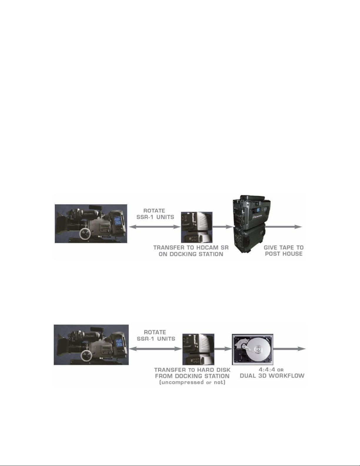
One possible workflow is to shoot with two SSR units. While one SSR is mounted on the camera,
the other is put on the docking station and transferred to an HDCAM SR recorder, and then
erased. Once the SSR on the camera is full, it is swapped with the empty one on the SSRD
docking station. This approach would allow productions to integrate the SSR footage with other
HDCAM SR material, in existing HDCAM SR workflows.
Some projects may elect to shoot with the SSR-1 at 4:4:4, and then transfer the footage onto hard
disk or other data storage medium for a “data” workflow, with or without compression. This
approach would also require rotating two or more SSR-1 units between shooting and transferring.

4--- Panavision SSR manual
V1.0
2.0 SSR CONNECTIONS
When the SSR is docked to the Genesis camera, the HD-SDI signal is input via the multi-pin
connector in the docking mechanism. Other possible connections are shown below.
ACCessory
input and output
NETWORK
at present for use by
Panavision service
technicians only
SD OUT
NTSC or PAL composite video output
GENlock
Tri-Level Sync input
can only be used
when SSR is not
docked on camera
HDSDI
422 monitor output
with optional characters
TC
LTC Timecode input
AUDIO
2 analog line-level
audio inputs

Panavision SSR manual --- 5
V1.0
2.1 SSRD Docking Station Connectors
The SSRD is a small docking station for the SSR.
When the SSR is docked to the SSRD, the HD-SDI inputs and outputs are available on BNC
connectors on the SSRD. The HD-SDI signal contains embedded audio from the SSR.
A 9-pin D connector on the SSRD allows the SSR to be controlled in slave mode by a serial
controller implementing the Sony P2 9 pin protocol, just like a Sony videotape recorder. This Sony
protocol compatibility makes it easy to integrate the SSR into existing post-production facilities
and workflows.
The SSRD is provided 12 Volt power via a 4-pin XLR or a 3-pin LEMO connector, which can also
serve as a loop-through power output.
A& B Link
HDSDI INputs
A& B Link
HDSDI OUTputs
REMOTE
RS422 serial control
Power INput
(11 to 17V)
Power
alternative INput
or loop-through
output
Power Switch

6--- Panavision SSR manual
V1.0
3.0 CONTROL PANEL
RECORD KEY
Push to start and stop recording. Record is always available, no matter what menu is displayed.
FUNCTION KEYS F1 – F4
Function of each key is indicated by the icon on its left, and changes with context. Pushing ALT
may display other functions.
MENU KEY
Push to enter or exit menu system, when changing a menu item, pushing acts as a cancel
function.
ALT KEY
Changes display to show alternate functions of the function keys. Also used to clear non-fatal
errors.
SELECT ENCODER - THUMBWHEEL WITH PUSH SWITCH
With the home screen, turning encoder will jog single frames forward and reverse, pushing will
select input video at the HD outputs and show the timecode generator time (TCG).
With other screens, turning the encoder is used to select, and pushing to activate, different menu
items.
DISPLAY ROTATE SWITCH
Rotates the display 90 degrees, used when the SSR is docked to the rear port of the camera
BACKLIGHT SWITCH
Select lcd backlight off, low or high intensity.
KEY LOCK SWITCH
Inhibit operation of all keys except record.
F1 F2 F3 F4
Function Keys
Icon on display
indicates
current function
Display Rotate
BackLIGHT
Brightness
Key LOCK
SELECT Encoder
Jog control
Push to see input video
Menu selection
Push to select menu item
RECord Key
Record Indicator
MENU Enter/Cancel
Show ALTernate function
Clear Error message

Panavision SSR manual --- 7
V1.0
4.0 DISPLAY
The SSR uses a 320 by 240 pixel LCD display as a graphical user interface (GUI).
The GUI displays information about SSR status, previously recorded clips, remaining capacity
and offers a menu system for changing user-controlled settings. A “home screen” is displayed
during the normal operating condition when the SSR is used as a recorder while docked to a
camera.
The home screen is divided into the 4 distinct areas shown below: TOP, MIDDLE, BOTTOM and
ICON
TOP and MIDDLE sections are changed by the menu system when activated.
BOTTOM and ICON sections are always displayed.
When the SSR is docked on top of the Genesis camera, use the Display Rotate switch to orient
the screen like this:
BOTTOM section.
The top line shows SSR position and status in small characters.
The big characters below show SSR position, timecode, TC generator or remaining capacity.
Remaining capacity is shown below as a “fuel gauge”, a green bar that decreases as the SSR
memory is recorded into.
TOP section
showing status
and error messages.
(Changes with MENU)
MIDDLE section
showing list of
previous recordings
with their duration and
frame rate.
This is also called the
clip list.
(Changes with MENU)
ICON section
showing the icons
for the 4 function
keys

8--- Panavision SSR manual
V1.0
4.1 Display Rotated for rear docked SSR
When the SSR is docked on the rear of the Genesis, use the DISPLAY ROTATE switch to
change the orientation, as depicted below.
Note that in this position the ICON section is below the BOTTOM section:
TOP section
STATUS
& error messages
(Changes with MENU)
BOTTOM section
Big timecode display
and capacity gauge
MIDDLE section
CLIP LIST
ICON section
For 4 function keys
F4
Stop
F3
Play
F2
Next
Clip
F1
Previous
Clip

Panavision SSR manual --- 9
V1.0
4.2 HOME SCREEN
The home screen shows a lot of information about the current status of the SSR. If errors occur
they are shown in the TOP section with an error code and a brief explanation. Most errors can be
dismissed after the error condition is removed. This is the case, for example, with an error
indicating that recording was attempted in the absence of input video. Critical system errors,
such as hardware failure, will cause a full screen error message to be displayed, and will disable
further recorder operation. (see Appendix A for more information about Error Messages).
Previous recordings are reviewed by using the 4 basic transport controls provided. Pushing the
Previous F1 and Next F2 Clip controls jumps to the first frame of a clip, pushing Play F3 starts
playback. Playback will continue until the end of all recordings is reached or when Stop F4 is
pushed.
You can safely start recording at any time, either by pushing the SSR RECord key, or by pushing
the Genesis camera record button. This will automatically create a new clip and recording will
start after all existing material. Starting to record will never erase previous recordings.
If you push Play F3 after pushing the RECord key to stop a recording, the SSR will playback the
last clip from the beginning. This “record review” option, indicated by a highlighting of the play
icon, disappears as soon as you push another button on the SSR.
F1
Previous Clip
F2
Next Clip
F3
Play
F4
Stop
Store Length
Frame rate
Format
Timecode
fps
System Mode
Input Status
Remaining
Capacity
Playback
Position
Sub TC
Display:
Playback
Position
& Status
Main TC
Display type.
Clip List
Status & Error
messages
Analog Audio
input level

10 --- Panavision SSR manual
V1.0
Pushing the ALT key yields other icons and transport controls:
ALT F1 cues the SSR to the first frame of the very first clip. ALT F2 cues to the first frame of the
very last clip. ALT F3 or ALT F4 will rewind or fast forward. Alternate functions for the home
screen are illustrated in section 4.3.
Pushing ALT F3 to rewind before the very first clip will cue up to 25 seconds of color bars with
legitimate timecode. This is useful when doing a dub from the SSR to a videotape recorder (see
Appendix C).
The key features of the HOME SCREEN are:
TOP section - Status and Error messages
The first line shows the current system mode (LP/SP), timecode base (24/25/30), format
(422/444), frame rate (23.98/24/25 etc...) and total SSR capacity at this frame rate.
The second line will display error code and message when needed.
The third line displays the total number of clips in the clip list, temperature status, key lock status
(yellow if locked with switch, red if locked with user code).
TOP section - Input Status
Input status is indicated by four characters: A, B, G and T. A white coloring indicates that the
input exists, a grey coloring means the input is absent.
The Aand Bcharacters indicate HD-SDI inputs Link A and Link B. When docked to Genesis, the
input status should generally display both A and B in white.
The Gcharacter indicates the status of the Genlock input, and is only present when the SSR is
used standalone.
The Tcharacter indicates the input status of external time code, it will have a green background
when the internal timecode is jam synced to the external code.
MIDDLE section - Clip List
The Clip List display shows up to four lines of previous recordings. The current clip is highlighted
in blue. The clip list shows either the Timecode (internal or external) that was recorded along with
each clip, or the SSR absolute position (analogous to control track). The clip list
timecode/position mode follows the setting of the Sub TC Display menu. See section 5.4.
BOTTOM section – Sub TC Display: Playback Position and Status
The smaller numerals show the current playback position, either in absolute position or as
timecode, alongside with the status (STOP, PLAY etc...). See section 5.4.
BOTTOM section - Main TC Display and remaining capacity fuel gauge
The remaining recording capacity of the SSR is shown both numerically as a timecode, and
graphically as a decreasing green bar. See section 5.4.
BOTTOM section – Bar Graph of Analog Audio input Level
If analog has been selected as the audio source, the bar graph will show the input level in EE and
record modes. Audio levels are not shown during playback and the bars are absent. To set a
precise audio input level you should use the expanded display in the audio menu, see section 5.5.
ICON section - Function key icons
The area on the right hand side (or bottom if the display is rotated) shows icons associated with
the four function keys. When a function key is pushed, most icons will invert and display a red
outline as a visual confirmation that the function has been selected.

Panavision SSR manual --- 11
V1.0
4.3 HOME SCREEN – Alternate functions
Pressing the ALT key will display the following alternative functions.
4.4 RECORD MODE
During recording the SSR position status line will turn red.
F1
First Clip
F2
Last Clip
F3
Fast
Forward
F4
Rewind
Select fps
variable speed mode
is shown here
F1
Previous Clip
F2
Next Clip
F3
Play
F4
Stop

12 --- Panavision SSR manual
V1.0
5.0 MENU SYSTEM
SSR Menus are accessed by pressing the MENU key on the control panel. There are 4 Standard
menus and 2 Alternative Menus (at present). Disabled menu items are shown in grey rather than
white.
You can navigate the list of menu items by rotating the Encoder thumbwheel. The current menu
item is highlighted in Blue. Push the Encoder thumbwheel to select the current item.
Pushing and holding down the ALT key gives access to 2 other menu pages that are used less
often.
F1
System
Settings
F2
Video
Settings
F3
Display
Settings
F4
Audio
Settings
F1
SSR specific
settings
F4
Initialization

Panavision SSR manual --- 13
V1.0
5.1 SUB-MENUS
For most menu items, changes are made via a sub menu system. To activate the sub menu for a
highlighted item, push the encoder switch, and the sub menu will then be displayed.
In the above example, the TC Source sub menu has been activated. To select a sub menu item
turn the encoder thumbwheel to highlight the new item and then push the encoder switch. To
cancel a sub menu selection, push the MENU key.
Certain functions will not display a sub menu but rather a new screen. For example, if the SET
TCG sub menu item is selected, the following screen appears.
F1
Next character
F2
Prev character
F3
Zero timecode
F1
System
Settings
F2
Video
Settings
F3
Display
Settings
F4
Audio
Settings

14 --- Panavision SSR manual
V1.0
5.2 SYSTEM MENU
The System Menu is reached by pushing F1 from any menu
F R A M E R A T E
F R A M E R A T E
Select system frame rate for playback. Disabled when the SSR is docked on Genesis, in which
case the frame rate is set in the camera menus.
F O R M A T
F O R M A T
Set system format as 4:4:4 or 4:2:2. Disabled when the SSR is docked on Genesis, in which
case the format is set in the camera menus.
T C G E N
T C G E N
Select PRESET or REGEN when using the SSR internal timecode generator. There is a SET
TCG sub-menu for both PRESET and REGEN. (See section 5.1 for illustration).
This menu item is disabled when external or HDSDI is selected as timecode source.
(See Appendix B for more information about TC options)
T C S O U R C E
T C S O U R C E
Select INTernal, INTernal RTC (real time clock), EXTernal LTC or EXTernal HDSDI video as the
timecode generator source. (See Appendix B for more information about TC options)
T C U S E R B I T
T C U S E R B I T
Select SOURCE or User Bits PRESET, TOD (time of day) or EXTernal TC, SET UB ( sub-menu).
R E F E R E N C E
R E F E R E N C E
Select AUTO, INTERNAL, EXTERNAL or INPUT video as the video reference source. AUTO is
the usual setting, and its priority is: input, external, internal. When the selected reference signal is
removed, the SSR will switch to another reference source, in the same priority. When the SSR is
docked to Genesis, this menu item is disabled and the reference is forced to INPUT video.
S E L E C T F R A M E
Used to turn on and off Select frame variable speed mode. Disabled when the SSR is docked on
Genesis, in which case the mode is set in the camera menus.
F1
System
Settings
F2
Video
Settings
F3
Display
Settings
F4
Audio
Settings

Panavision SSR manual --- 15
V1.0
5.3 VIDEO MENU
The Video Menu is reached by pushing F2 from any menu
M O N O U T
M O N O U T
Normally leave on AUTO. This menu item determines the HD-SDI 422 video output for the
“HDSDI” BNC (next to TC). See section 2.0
Select between AUTO, LinkA, LinkB and 444 modes. 444 mode converts 444 to 422.
This setting defaults back to AUTO when the SSR is power cycled.
Do not select LinkA or LinkB MON OUT when using the 444 format, as this will create a faulty
signal.
T G
T G
Enable and select video test signal generator. Select between Off, CB (color bars),
PATHological, Ramp and Black.
(The grey and magenta PATHological signal is used to check the serial digital interface)
S D M O D E
S D M O D E
Select the aspect ratio on the SD OUT BNC (next to GEN). See section 2.0
Select between Letterbox, Edge crop or Squeeze to fit the 16 by 9 frame in the SD (standard
definition) 4 by 3 aspect ratio.
S D F O R M A T
S D F O R M A T
Select the format of the composite video output for the SD OUT BNC: NTSC or PAL.
M O N I T O R
M O N I T O R
Select the video output for the LINK A, LINK B and HDSDI monitor outputs in non-play modes.
Select between PB/EE and PB.
In PB/EE mode, playback is selected when PLAY, SHUTTLE, FWD or REWIND and input video
is seen when in STOP. If there is no video input then EE mode will not be selected.
In PB mode, playback video is always seen on the output, even when the SSR is stopped, in
which case a still frame is displayed.
F1
System
Settings
F2
Video
Settings
F3
Display
Settings
F4
Audio
Settings

16 --- Panavision SSR manual
V1.0
5.4 DISPLAY MENU
The Display Menu is reached by pushing F3 from any menu
Timecode versus Position
The 8 digit numbers in the hour : minute : second : frame format on the SSR can indicate either
Position or Timecode.
Position is analogous to Control Track. The Position is set to 00:00:00:00 at the beginning of the
first recording on the SSR, and incremented with every subsequent recording. Position tells you
how much you have recorded.
The Timecode signal is set either internally or externally in the System Menu. See section 5.2.
Main TC Display Values
The Main TC display is the big timecode number at the bottom of the display. It can indicate 4
different values:
1. Remaining capacity left in the SSR, displayed in the current system timecode format.
This mode is indicated by a REM box on left of the Main TC.
F1
System
Settings
F2
Video
Settings
F3
Display
Settings
F4
Audio
Settings
Main TC
Disp
Sub TC
Disp

Panavision SSR manual --- 17
V1.0
2. Position - Current position, starting with a value of zero at the beginning of the first recording
made on the SSR. This mode is indicated by a POS box on left of the Main TC.
3. Timecode - Current timecode associated with the currently displayed frame. This mode is
indicated by a TC box on the left of the Main TC HH;MM;SS:FF display.
4. Timecode generator.This is the TC set in the System Menu. This mode is indicated by TCG
box on left of the Main TC. The only occasion you will see TCG is on the HOME screen, when
you push the Encoder jog knob to see the EE video signal.
M a i n T C D i s p
M a i n T C D i s p
You can select 1 of 4 settings:
1. Remaining capacity
2. Position
3. Timecode
4. Auto – In record the Main TC will display remaining capacity, in playback the Main TC will
display playback Position or Timecode. The playback mode (Position or Timecode) depends on
the setting of the Sub TC Display discussed below.
S u b T C D i s p
S u b T C D i s p
The sub timecode display is the smaller-sized timecode right above the Main TC.
You can select either:
1. Position - Current position of the SSR starting from zero at beginning of first recording.
2. Timecode – The timecode associated with the current frame.

18 --- Panavision SSR manual
V1.0
NOTE
The Sub TC Display setting of Position or Timecode determines the numerical setting for:
1. The Sub TC Display itself
2. Main TC Display (when it is in AUTO mode)
3. The Clip List
For example, if the Sub TC Display is set to Position, the Main TC will display Position if it is in
AUTO mode, and the Clip list will also show Positions.
C H A R A C T E R S
C H A R A C T E R S
Select whether to turn characters On or Off in the video monitor 422 output and the SD output.
A sub-menu allows you to define the on-screen characters:
1. REC STATUS – Turn the recording status On or Off. When on, a red “REC” will appear on
right-hand bottom of the image during recording.
2. TIME DISPLAY – Select Auto, Remain, Timecode, Position or Off
Time display
Record
Status
Table of contents
Popular Storage manuals by other brands

ADIC
ADIC FastStor 2 user guide

Rutter
Rutter VDR-100G3 installation manual

Silicon Laboratories
Silicon Laboratories C8051F341 product manual

Sans Digital
Sans Digital ACCUNAS AN104LS Quick installation guide

Overland Storage
Overland Storage NEO 8000 instructions

Quantum
Quantum Fireball ST Mounting Guidelines

RaxGo
RaxGo RGFSKR user guide

Seagate
Seagate CHEETAH ST336753FC installation guide

Buffalo
Buffalo LinkStation Pro Quick setup guide

Transcend
Transcend Portable Hard Disk TS40GHDU1 user manual

Spectra Logic
Spectra Logic Spectra 12000 supplementary guide

Seagate
Seagate EXOS ENTERPRISE ST16000NM001G product manual