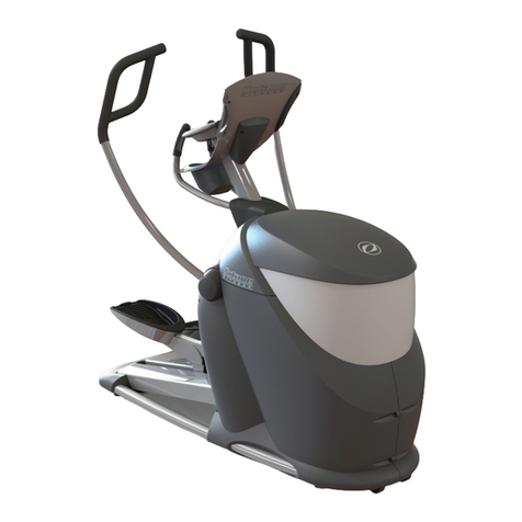
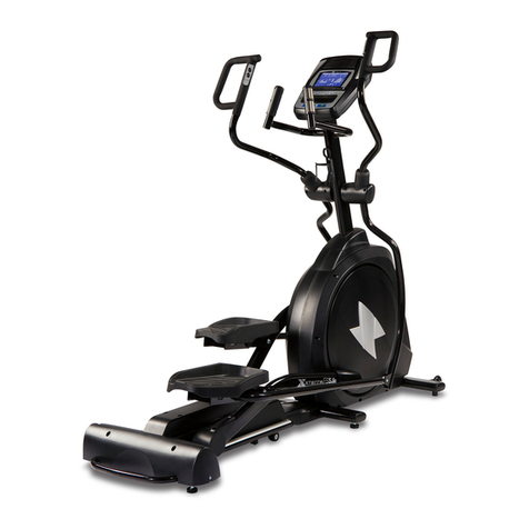
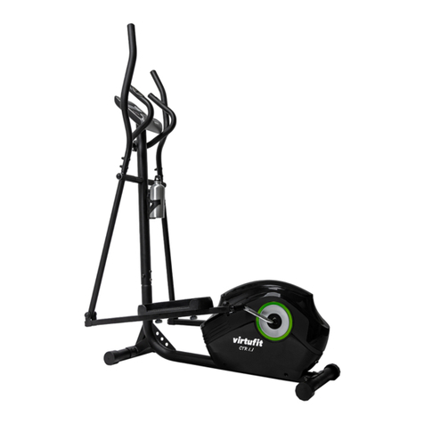
Panther Elliptical User manual

Panther_BilingualMAN_TP_ENG/SPAN_V1_110802


Table
of Contents
Important Safeguards ....................4
Assembly & Usage
Before Starting ......................5
Hardware Provided ..................5
Assembling .........................6
Handle Bars ........................8
Digital Monitor ......................8
Adjusting Resistance.................9
Dual Movement .....................9
Exploded Diagram/Parts List .............10
IMPORTANT!
Please read all instructions carefully before using this product.
Retain this manual for future reference.

4
Please note the following precautions before assembling or
operating the Panther Elliptical.
1. THE PANTHER’S MAXIMUM USER WEIGHT IS 250 LBS. If your
weight exceeds this limit, please DO NOT USE.
2. The Panther Elliptical is not safe for use by children. Please keep
children and pets away from the Panther Elliptical and do not leave
UNATTENDED with machine at any time.
3. If you experience dizziness, nausea, chest pain, or any other unusual
symptoms during use, DISCONTINUE use immediately and CONSULT
A PHYSICIAN.
4. Place the Panther Elliptical on a stable level surface. This machine is
not meant to be operated outdoors or near water.
5. For safety and comfort, please always wear appropriate workout
attire while using your Panther Elliptical. Running or training shoes are
strongly suggested.
6. Use the Panther Elliptical only in the way described in this manual. Any
unauthorized accessories or add-ons should not be used at any time.
7. When operating, make sure NOT to place any sharp objects around
the Panther Elliptical.
8. It is strongly suggested that any disabled users NOT use the Panther
Elliptical without the supervision of a health professional or physician.
9. Make sure to always stretch and warm up properly before using your
Panther Elliptical.
10. DO NOT operate the Panther Elliptical in the event of a malfunction or
if unusual noises are heard during use. SUSPEND USE and contact
customer care immediately upon discovering any issues.
WARNING: ALWAYS CONSULT YOUR PHYSICIAN BEFORE STARTING ANY EXERCISE
PROGRAM. THIS IS ESPECIALLY SUGGESTED FOR THOSE WITH ANY PRE-
EXISTING HEALTH ISSUES.
PLEASE MAKE SURE TO READ ALL INSTRUCTIONS PRIOR TO USING.
PLEASE NOTE TRISTAR PRODUCTS, INC. ASSUMES NO RESPONSIBILITY FOR
PERSONAL INJURY OR PROPERTY DAMAGE SUSTAINED BY OR THROUGH THE USE OF
THE PANTHER.
IMPORTANT SAFEGUARDS
KEEP THESE INSTRUCTIONS

5
ASSEMBLY & USAGE
I. Before Starting
1. Choose a comfortable and spacious work space. It’s advisable to
assemble your Panther Elliptical in an open space with adequate lighting.
Since the Panther Elliptical is transportable to some extent, it does not
have to be assembled in the exact location where it is meant to be used.
However, for your safety and protection of your property, you should avoid
having to haul the machine across a large area of space. Make sure to
protect your oor or carpet using a large mat before starting assembly to
avoid any damage to your property.
2. You will need the following tools to assemble the Panther Elliptical.
• Adjustable wrench
• Standard screwdriver
• WD40 or spray lubricant
• 2 small Allen keys, 1 large Allen key (provided)
3. Please make sure to understand all safety precautions prior
to assembly.
II. Hardware Provided
Organize your bolts and nuts according to the below illustration prior to
assembly. Nuts and bolts are identied by their size. For more information,
refer to exploded view diagram and parts list on pages 7-8 of this manual
Note: The illustration below does NOT show actual size of hardware.
2 small Allen keys and 1 large Allen key (not shown)
#46 3/8"x60 Carriage Bolt (4X)
#12A Handlebar Shaft
#47 3/8" Acorn Nut (4X) #51 M13 Spring (split)
Washer (2X)
#58 Hinge Screw (2X)
#12B Pedal Hinge Bolt (2X) #17 Knob Bolt (2X)
#44 3/8"x48 Bolt (4X)
#45 3/8"Nut (4X) #48 1/2"Spring Nut (2X)

6
III. Assembling Your Panther Elliptical
1. Install cylindrical Foot Bases (front #2 and rear #3) to the Main Frame (#1)
using two 3/8”x60 Carriage Bolts (#46) and two 3/8” Acorn Nuts (#47).
(See Fig 1) The Front Base (#2) has wheels for transporting your Panther.
(3) Rear Cylindrical Base
(47) 3/8"
Acorn Nut
46B Washer M10
(1) Main Frame
(46) 3/8"x60 Carriage Bolt
(2) Front Cylindrical Base
with
Wheels
FRONT
REAR
Fig 1

7
4. Attach right Pedal
(#11) to Right Pedal
Tubing (#6R).
Use two 3/8” x17/8”
Bolts (#44) and
two 3/8” Nuts (#45).
Repeat these steps on
left side. (See Fig 3)
NOTE: Use WD40 or any tool lubricant to reduce friction when screwing in the
Pedal Hinge Bolt to the Crankshaft. The bolt may become tight at times and
may even feel like it will no longer screw in. However, making sure screw is
properly lubricated and performing occasional back and forth twists to the bolt
will ensure that it goes through with more ease. NOTE: Both Pedal Hinge Bolts
will not have the same screw pattern and both the left and right sides will tighten
using opposite tightening directions.
2. Insert the Handle Bar Shaft (#12A) through the Coupler Bar of either the
right or left side. Making sure the
Handle Bar Shaft (#12A) goes
all the way through the main
frame and reaches the outer end
of opposite Coupler Bar. Make
sure to secure Handle Bar Shaft
by using the Hinge Screw (#57),
Sharp Washer (#49) and Spring
Washer (#52) by tightening
the Hinge Screw at each end
simultaneously with the 2 Small
Allen Keys provided.
3. Now to complete assembly of the arm bar, insert a Pedal Hinge Bolt (#12B)
through the Pedal Tubing (#6R for right side, #6L for left side). Screw the
Pedal Hinge Bolt using the Large Allen Key provided, into the Crankshaft,
which is already installed within the Panther’s main frame. Secure the Pedal
Hinge Bolt at the inner end with a ½” Spring Nut (#48) and a ½” Spring
Washer (#51). (See Fig.2)
Steps 2 through 4 will detail assembly of Pedals and Coupler Bars. Repeat these
steps on each side (Left and Right) before moving on to Handle Bar assembly.
Fig 3
44
6
45 11
Fig 2
27
12B
48
51
6R
4
12A 49
57
52
1

8
IV. Handle Bars
It is easy to switch the Handle Bars (#7L, #7R) between the total body-action
mode and the stationary mode during your workout.
5. Total body-action mode: Attaching the Handle Bars to the Coupler Bars
will allow for the Pedals and Handle Bars to move simultaneously and
provide a total body- action workout.
Always make sure to select a height setting that is most comfortable for you and
always place both Handle Bars at the same height. Once you decide on the
most comfortable height, use two Knob Bolts (#17) to secure Handle Bars in
place. (See Fig.4)
6. Stationary mode: Using stationary mode will
allow you to focus your workout on your lower
body. Keep Handle Bars stationary by
attaching them to the Tubing on the Main
Frame between the Coupler Bars.
As with the total body-action mode, it is important
to select a height setting that is most comfortable
for you and always place both Handle Bars at
the same height. Once you decide on the most
comfortable height, use two Knob Bolts (#17)
to secure Handle Bars in place. (See Fig.4)
7L
Fig 4
17
5
V. Digital Monitor
7. Slide the Digital Monitor (#50) into the bracket welded on the Main Frame.
Connect the Monitor to the sensor wire attached to the Main Frame. (See
Fig.5) Two AA batteries are included for your convenience. Monitor will
automatically shut off when not in use to preserve battery life.
The Digital Monitor will track your progress
and show the following information during
your workout:
TIME: How long you have been exercising
SPEED: How fast you are running
DISTANCE: How far you have run
CALORIE: The amount of calories burned.
To automatically alternate between the
four readouts press the SCAN button and
the 4 different categories will appear in
short intervals.
(50) Electronic
Monitor
Monitor
Bracket
Fig 5

9
VI. Adjusting Resistance
You are now ready to use your Panther Elliptical for the rst time! As you
become familiar with the machine, you can adjust the resistance in accordance
with your tness level.
1. The Resistance Knob (#36) found at the center of the Main Frame can be
used to intensify resistance and adjust the intensity of your workout.
2. For a more intense workout and greater
resistance control, you may loosen or
tighten the Tension Belt (#35) by adjusting
the strap. You must rst set the Resistance
Knob to its lowest setting. Then readjust
the Tension Belt at the buckle on the Main
Frame. The tighter the Tension Belt is
strapped around the wheel, the higher the
resistance and the more intense your
workout will become. Please make sure
to readjust the Resistance Knob after
adjusting the tension belt.
VI. Dual Movement
Keep in mind that your Panther Elliptical features DUAL Movement!
(Forward and backward motion)
Forward pedaling reinforces your quadriceps muscles, while backward pedaling
reinforces your hamstrings. This will allow for a more complete workout and will
make you feel more fullled as you are able to attack various muscle groups will
little to no effort!
Tension Belt Buckle
(under center beam)
Tension
Adjustment
Knob The more tightly
the Tension Belt
wraps around
the Fan Wheel,
the harder it is
for you to pedal
(more tension)
Tension
Belt (35)

10
EXPLODED DIAGRAM
NOTE: This is an exploded view of the Panther Elliptical. Some parts may
come assembled already.
Part No. Description Qty
1 Main Frame 1
2 Front Foot Base 1
3 Back Foot Base 1
4 Right Coupler bar 1
5 Left Coupler bar 1
6R Right Pedal Tubing 1
6L Left Pedal Tubing 1
7R Right Handle Bar 1
7L Left Handle Bar 1
8R Right Chain Cover 1
8L Left Chain Cover 1
9 Left Fan Wheel 1
10 Right Fan Wheel 1
11 Pedal 2
12A Handle Bar Shaft 1
12B Pedal Hinge Bolt 2
13 End caps(ø2") 4
14 Foam grips 2
15 End caps(ø2") 2
16 Plastic bushing(OD29XID26x80) 4
17 Knob Bolt 2
18 Plastic Roller 2
Part No. Description Qty
19 Steel bushing OD22.4xID16 10
20 Steel bushing OD12.5xID9.7 4
21 Brass bushing OD14xID10 2
22 Fan wheel axle 1
23 Nut M10 3
24 AL belt 1
25 Nut M10 2
26 Sensor 1
27 Crankshaft 1
28 Chain Wheel 1
29 W.S. OD40.5xID24 1
30R Collar Housing 1
30L Collar Housing 1
31 Collar ball 2
32 Collar Housing 2
33 Nut M22 1
34 Chain 25H×220L 1
35 Tension Belt 1
36 Resistance Knob 1
37 Tension Spring 1
38 Chain cover screw M5×15 2
39 Chain cover screw M5×45L 6
Part No. Description Qty
40 Tension fix screw M5×18L 1
41 Fan wheel fix screw M4×25L 16
42 Bolt 1/4"x48L 2
43 Nut 1/4" 2
44 Bolt 3/8"×ø17/8*0 4
45 Nut 3/8" 6
46 Carriage Bolt 3/8"x60L 4
46B Washer OD21xID10.2 4
47 3/8"Acorn Nut 4
48 Spring Nut 1/2" 2
49R&L Sharp Washer OD23xID16 2
50 Digital Training Computer 1
51 Spring Washer OD21xID13 2
52R&L Spring Washer OD16.4xID10.5 2
53 Nut 1
54 Fan wheel screw M4×15 4
55 Washer 1
56 Bolt 3/8"x53L 2
57 Sharp Washer 2
58R&L Hinge screw 3/8”x20L 2
Distributed by: Tristar Products, Inc.
© 2011 All Rights Reserved.
Table of contents