8
Troubleshooting
SAFETY
Safety Guidelines
• Do not use in wet or humid conditions
• The cables between charger and battery should be kept as short as possible to prevent
excessive voltage drop (suggested cable length: 50cm - 100cm). Too much voltage drop will
lead to longer charging period.
• Temperature raising on case during charging is a normal behavior.
• Dismantling or changing components of the charger is forbidden.
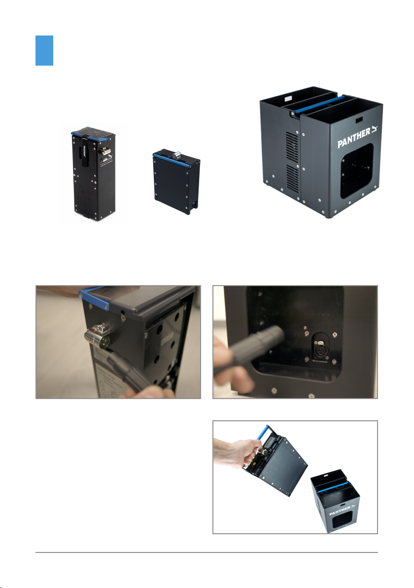
• Charger should be in the OFF mode before making battery connection or disconnection.
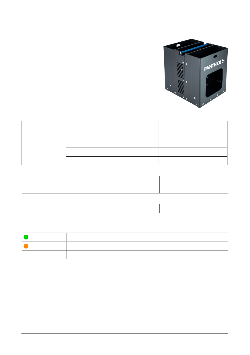
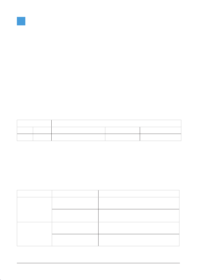
The charger provides a DIP switch behind the panel used to switch dierent factory charging
parameters. Please refer to the table below for corresponding curves on dierent positions of
the DIP switch.
DIP SW position 24V model
1 2 Description Vboost Vfloat
O O Program mode, AGM battery 29.0 27.0
General Operation
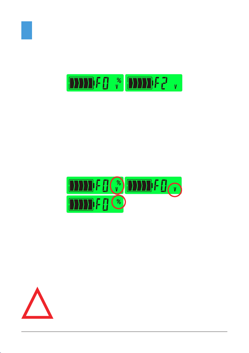
At the beginning stage of operation, the charger provides the largest current with 28.8V dc of
output voltage to charge batteries, the LED indicator will flash in orange. After a period of time
(probably a couple of hours) the charging current will decrease gradually.
After reducing to 10% of its maximum value, the charger will go into „float charge“ stage.
Output voltage will drop to 27.6V and the LED indicator can flash in green.
Failure state Possible Cause Suggested Solutions
Unable to charge
the battery
Power switch is in the
OFF position
Switch to the ON position
Input AC voltage is too
low
Make sure the input source is between
90~264VAC
LED indicator
does not turn
Green after a long
charging period
Battery is old or
damaged
Replace with a new battery
Output cables are to
thin
Replace with an appropriate wire gauge