Paoli DPH 220 User manual

Instruction Manual
DPH 220 - DPH 460
Page 1
This manual contains operating instructions and maintenance schedules for the high pressure breathing air compressors. Operators
must read and understand all information inside the manual.
ATTENTION. This machine can be used only after a careful reading of this instruction manual. The machine may only
used to produce compressed air. Other use is strictly prohibited. The manufacturer and the supplier void all responsibility
for damage or injury resulting from failure to follow these instructions.
1. GENERAL INFORMATION:
Before using the machine please put your attention to this
general information:
1. Personnel engaged to operate the machine must have read the
instruction manual before beginning work, especially the safety
notices chapter.
2. Personnel may not wear long hair loose, loose clothing or
jewellery, including rings.
3. Keep all safety and danger notices on the unit complete and in
readable condition.
4. No modifications may be made to the unit which could impair
safety without first obtaining permission from the suppliers.
5. Piping must be thoroughly checked (pressure and visual inspection)
by the operator at appropriate time intervals, even if no safety related
faults have been noticed..
6. Intervals stipulated or given in the instruction manual for recurring
checks/inspections must be adhered to.
7. It is absolutely essential that the workplace is appropriately
equipped for maintenance measures.
8. Work on/with the unit may only be carried out by reliable personnel.
Observe the legal minimum age permissible.
2. GENERAL FEATURES:
The DPH 220 - DPH 460 high pressure compressors are designed
to compress air for breathing as required in diving and fire
fighting applications. The max pressure is 225 bar or
330 bar depending on unit.
The compressor unit comprises the following major assemblies:
. Compressor block
. Electric or petrol/diesel engine
. Filters
. Filling assembly
. Protection and anti-vibration frame
. Automatic condensate drain*
. Electric control system**
. Automatic switch on/off*
. ALLUMINUM frame
(*) Optional extra according to order
3. COMPRESSOR GROUP:
The compressor block DPH 220 - DPH 460 is used to compress air in the high pressure range up to 330 bar (4500 psi). The compressor
block is of a four stage, four cylinders design. The cylinders are arranged in the 1st stage on the left, 2nd stage on the right, 3rd and
4th stage on the centre side looking from the filter side. The compressor blocks are particularly suitable for continuous operation
because of their rugged design and the corrosion resistant intermediate filter and cooler assemblies. Smooth running is a particular
feature of this DINO PAOLI SRL design. The moving parts of the driving gear are all equally balanced. This results in a vibration-free
running. The driving gear is fitted with energy saving cylinder roller bearings. The upper and lower connecting rod bearings are also
roller bearings. Crankcase, cylinders and heads are obtained from the gravity dies. Connecting rod are extracted from casting dies.
Cylinder are in cast iron inside an aluminium pipe.
www.air-allied.com.au
Air & Allied Sales (Pacific) Pty Ltd
www.air-allied.com.au

Instruction Manual
DPH 220 - DPH 460
Page 2
Description
1. Intake Filter
2. 1st stage
3. Inter-cooler 1st stage
4. 2nd stage
5. Inter-cooler 2nd stage
6. 3rd stage
7. Inter-cooler 3rd stage
8. 4th stage
9. Inter-cooler 4th stage
10. Oil indicator
4. TECHNICAL DATA
Compressor unit
DPH 220 - DPH 460
Operating pressure
PN 200
PN300
Delivery *
100 L/min.
100 L/min.
Final pressure safety valve
225 Bar
330 Bar
Compressor block
DPH 220 - DPH 460
Number of stages
4
Number of piston
4
Cylinder bore stage 1
60 mm
Cylinder bore stage 2
38 mm
Cylinder bore stage 3
19 mm
Cylinder bore stage 4
9,5 mm
Piston stroke
23 mm
Intermediate pressure stage 1
2,5 Bar
Intermediate pressure stage 2
15 Bar
Intermediate pressure stage 3
55 - 65 Bar
Intermediate pressure stage 4
225 - 330 Bar
Oil capacity
0,350 L.
Oil Type
SHELL CORENA P150
Max permissible ambient temp.
-5°C Min. +45°C Max. (+25°F Min. +113°F Max.)
Max permissible inclination of compressor
20°
Max dampness
80%
Max sea level
2000 m sea level
Weight
25 Kg.
Drive engine
DPH 220
Type engine
230 Volt / 50–60 Hz
Power
3,0 Hp 2poli
Speed
2940 r.p.m.
Type of enclosure
IP 54
Current rating
16,5 A
Petrol engine
DPH 460
Switch on/off
MANUAL
Cubic capacity
169 ml.
Power
4,4 Kw-6,00 HP / 3600 r.p.m.
5. SAFETY MEASURES
5.1. Fundamental safety notices:
Important instructions concerning the endangerment of personnel, technical safety and operating safety will be specially emphasized by
special marks placing on the machine.
For safety reasons you can find some components mounted on the compressors in order to prevent damages. These parts must not be
changed or removed in any case. Before please consult our technician.
www.air-allied.com.au
Air & Allied Sales (Pacific) Pty Ltd
www.air-allied.com.au

Instruction Manual
DPH 220 - DPH 460
5.2. Authorized use :
The unit is built according to state of the art technology and established safety technical regulations. Nevertheless, its use can cause
danger to life and limb of the operator or third parties or damage to the machine and other equipment. Operate the unit only in
technically perfect condition in accordance with regulations and safety danger notices detailed in the instruction manual. The
manufacturer/supplier is not responsible for damage resulting from a wrong utilisation of the machine. The user alone is responsible for
this risk. The compressor is built to produce top quality breathing air according to DIN EN 12021 rules.
5.3. Safety notices for operation
:
- Ensure that only trained personnel work with the machine.
- Filling hoses must be in satisfactory condition and threads undamaged.
- Ensure intake air is free from noxious gas, exhaust fumes and solvent vapour.
- The use of petrol and diesel compressors is forbidden in indoor place.
- Check the unit externally for damage and faults periodically. Inform the department/person responsible immediately if anything is not
as is should be (including operation). If necessary, shut the machine down immediately and make it safe.
Observe switching on and off processes and monitoring indications according to the instructions manual.
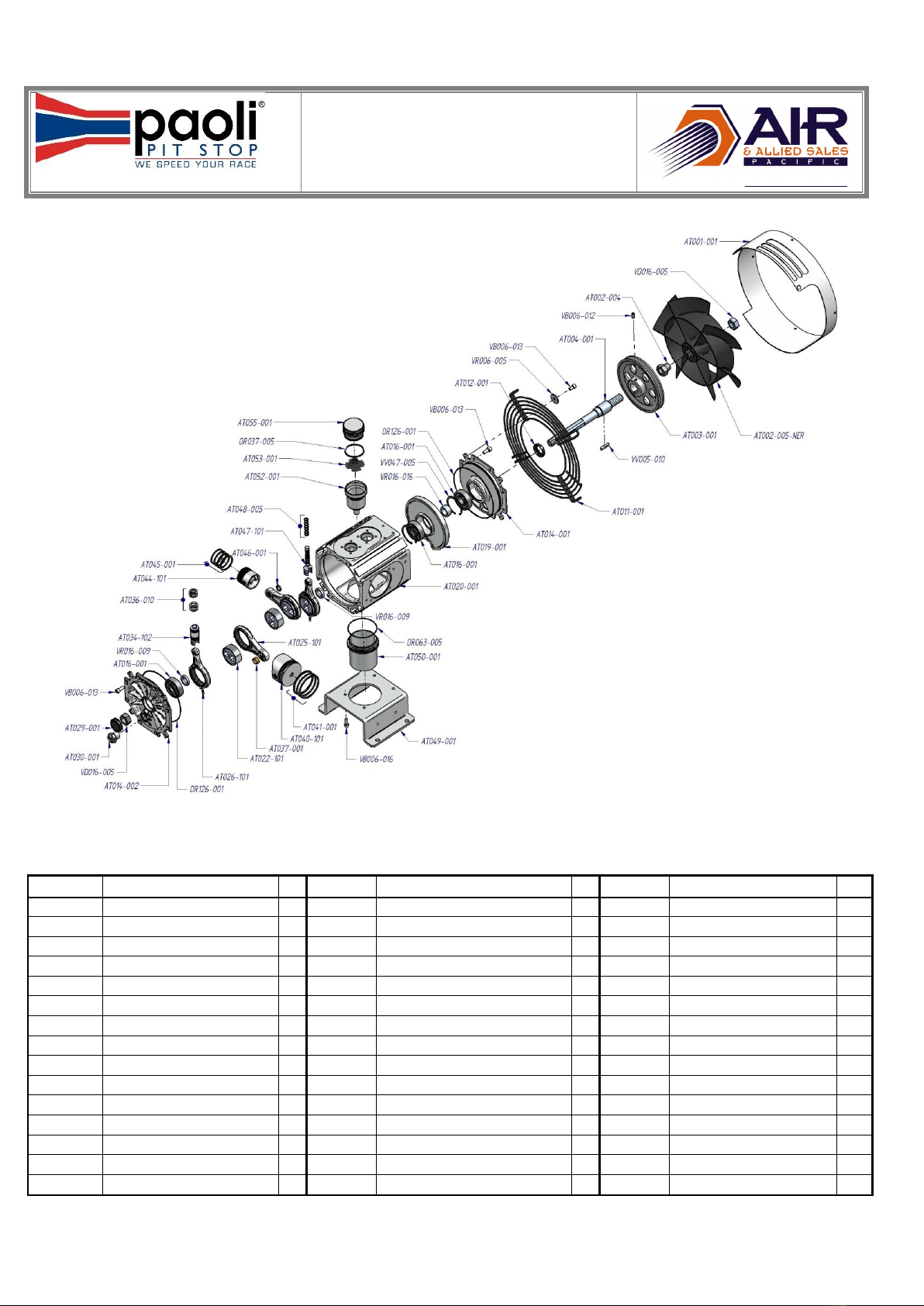
- Use only DINO PAOLI SRL original parts and equipments.
- Drain the valve regularly if manual drain valve. Check every 10 minutes the valve if automatic drain valve.
- Switch off the machine when do not use it.
- Clean oil, fuel or care products from, the machine, in particular the connections and screw joints, before carrying out
maintenance/repair work. Do not use aggressive cleaning fluid. Use a fibre-free cleaning cloth.
- Completely remove all covers/seals after cleaning.
- Use only original fuses with specified current rating. If there is a failure in the electric energy supply, shut the machine/unit down
immediately.
- Work on electric units or operating equipment may only carried out by a qualified electrician or by a person under the instruction and
supervision of qualified electrician according to electric technical regulations.
- The electrical equipment of a unit must be regularly checked.
- When working in small rooms, observe any national regulations.
- Depressurize system and pressure lines before commencing repair work.
- With regard to oil, grease and other chemical substances, observe the relevant safety rules for the product.
- When switching on the machine, check the arrow to ensure correct direction of rotation of the drive motor.
- The cooling fan of the compressor must have a minimum clearance of 50 cm.
5.4. Electrical installation:
For electrical installation must follow these steps:
Do check by an electrician that the plant complies with regulations and bear the maximum absorption of the compressor.
Check that power is coming to the voltage required by the compressor and the power cord used is not undersized.
WARNING: if the motor is three-phase, make sure that the fan of the compressor turns in the right direction of the arrow. To reverse
the rotation enough to reverse up by trained two of the three phases of the power plug.
Make sure the grounding is connected firmly on the plug and on the electrical system.
If you change the power cord make sure it is appropriately sized.
6. OPERAZIONI PER L’AVVIAMENTO:
6.1 Preparation for operation.
WARNING: this machine is built to produce breathing air. It is not suitable for compression of oxygen. Explosion occurs if an oil
lubricated compressor is operated with pure oxygen or gases with oxygen content of more than 21%!
All compressor units are tested prior to delivery to the customer, so after correct installation of the unit there should be no problem
putting it into operation, observing the following points:
Prior to first operation read Instruction Manual carefully. Make sure that all persons handling the compressor and the filling station are
familiar with the function of all controls and monitors.
Immediately after switching on the system for the first time check the direction of rotation of the motor for compliance with the arrow
on the unit. If motor turns in the wrong direction, the phases are not connected properly. Shut down unit immediately and interchange
two of the three phase leads in the switch box. Never change leads at the motor terminal board.
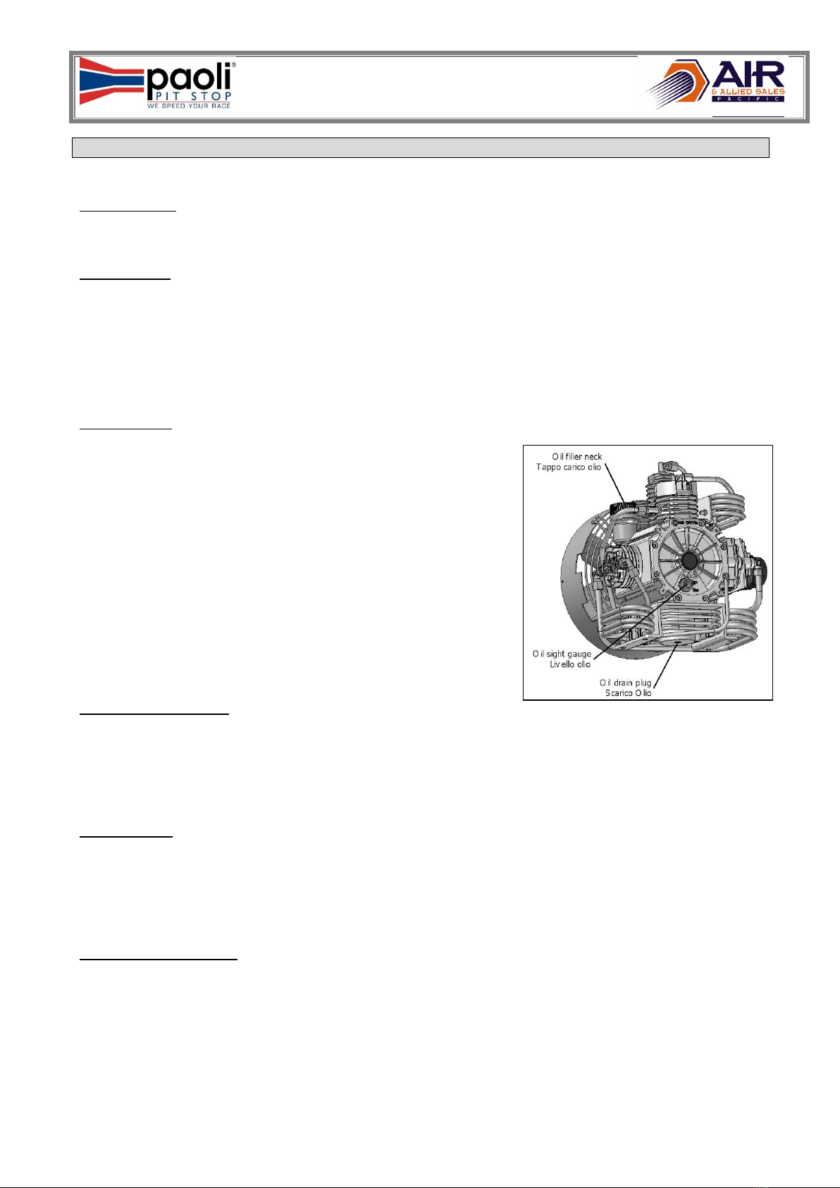
Prior to each operation check the oil level. Only for petrol unit: - check engine oil level according to manufacturer’s instruction manual -
check fuel tank. Top up if necessary - open fuel shut-off valve.
Every time the unit is started up check all systems for proper operation. If any malfunction is observed stop unit immediately and find
the cause of the fault or call the service department.
www.air-allied.com.au
Page 3
Air & Allied Sales (Pacific) Pty Ltd
www.air-allied.com.au

Instruction Manual
DPH 220 - DPH 460
6.2. Starting the unit:
Unit with electric engine without compressor control system:
The motor is switched on manually by pressing the start button. Machine does not be left alone during working. Check continuosly the
right function.
On units without automatic condensate drain, the manual condensate drain valves have to be opened before starting the unit, as soon
as the unit is running the valves can be closed again. Every 8/10 min drain the valves.
Units with electric engine with automatic control system:
This model is delivered with an automatic control system.
Before starting check point 6.1 and then press ON button. Switch off the machine pressing STOP button.
Units with petrol engine:
Open condensate drain valves on the filters to release pressure, so that motor start without load. Set choke to position START. Start
engine with recoil starter or crank handle. As soon as motor runs smoothly return choke to normal operating position.
For all units:
Close condensate drain valves tightly and run unit to final pressure. Check final pressure safety valve and pressure gauge. As soon as
final pressure is reached and final pressure safety valve blows off, open condensate drain valves and drain condensate - unit is ready for
filling operation.
7. FILLING PROCEDURE:
7.1. Connecting the bottles:
WARNING: Filling hoses must be in satisfactory condition and threads undamaged. Pay particular attention to damage on the interface
from hose fitting to hose. If the rubber is scored, hose must be discarded otherwise water can enter and attack wire gauze causing it to
rust.
Normally connectors are allowed for pressures up to 200bar (2.850psi).
Please follow the process below:
- Connect air bottle to filling valve.
- Open filling valve.
- Open bottle valve-bottle will be filled. .
- Switch on the compressor.
- Upon reaching final bottle pressure close bottle valve first, then filling valve by returning handle to closed position.
- Remove compressed air bottle.
- Depressurize unit before opening valve-A to avoid damage to the change - over device.
If it is necessary more pressure of 220bar please ask for the suitable material: safety valves and connectors are
different.
8. MAINTENANCE :
8.1. Maintenance record:
We recommend that all maintenance work is recorded in a service book, showing the date and details of the work carried out. This will
help to avoid expensive repairwork caused by missed maintenance work.
Please fill in the appropriate lines to show what maintenance work has been carried out, and sign and date.
Remember:
1–always shut down and decompress the complete system prior to carrying out any work on the compressor;
2–never repair pressure lines by soldering or welding;
3–only use original spares for maintenance or repair work.
www.air-allied.com.au
Page 4
Air & Allied Sales (Pacific) Pty Ltd
www.air-allied.com.au

Instruction Manual
DPH 220 - DPH 460
Page 5
8.2. Maintenance schedule:
After first 25 operating hours
Date
Segnature
Clean intake filter and intake filter cartridge
Check Oil level ( Max. RED POINT )
Cartuccia Filtro Carboni –setaccio
Check tightness of all cooler-pipes and couplings
Check tightness of O-rings
Check functioning and tightness of filling valve
Check zero position on final pressure gauge when
depressurized
After first 50 operating hours, at least annually
Date
Segnature
Oil change 350 ml.
Check and clean intake filter element 1st stage
Check filter and cartridge
After first 500 operating hours, at least annually
Date
Segnature
Valve change
Change intake filter element 1st stage
Check blow-off pressure of final pressure safety valve
After repair work
Date
Segnature
Check functioning and tightness of filling valve
Clean intake filter element 1st stage
Check tightness of O-rings
Check zero position on final pressure gauge when
depressurized
www.air-allied.com.au
Air & Allied Sales (Pacific) Pty Ltd
www.air-allied.com.au

Instruction Manual
DPH 220 - DPH 460
Page 6
9. MAINTENANCE WORK
This chapter contains the maintenance work as well as short functional description for each component.
9.1. Lubrication :
The lubrication system is a Splashed lubrication. Mechanic lubrication by connecting-rod movement. Connecting-rod has a metal
piece below that splashing in the oil during the fast movement causes a spray inside the cylinder.
9.2. Type of oil :
Using the correct oil is of vital importance for life and maintenance of the compressor. DINO PAOLI SRL has a particular oil studied and
tested for the best operation of his machine. Depending on the application of the compressor the requirements placed on the oil are:
- low deposits
- No carbonizing effect, especially in the valves
- Good anti-corrosive properties
- For breathing air application, also physiological and toxicological suitability.
Due to the thermal load on the compressor only high quality oil should be used. You are recommended to restrict oils to those which
have been approved by us: oil for not mixed air (21% O²).
9.3. Oil change :
Please follow the procedure as below:
- Ensure to have a sufficient quantity of oil.
- Run compressor warm.
- Remove red cap from oil filler neck and drain oil while still warm by means of oil
drain plug.
- Remove oil filter.
- Mount a new filter element.
- Fill new oil though filler neck to Max.—mark at sight gauge.
9.4. Changing the oil type:
To avoid severe damage to the compressor unit when changing the oil type, the following measures should be strictly adhered to:
- Follow the procedure Chapter 9.3.
- Change or clean all parts with old oil.
- After approx. 10 operating hours check lubricating oil for degree of contamination, and change oil again if necessary.
- Fill compressor with the new oil and do not mix different oils.
- Refill compressor with same oil, only.
9.6. Intake filter
A dry micronic filter is used to filter intake air. The filter cartridge must be cleaned or changed at regular intervals according to
maintenance schedule. Do not use any cleaning fluids which are a hazard to respiration.
Please clean intake filter as following:
- Remove micronic filter cartridge.
- Clean with brush or by blowing air inside out.
- Change with a new filter and make sure that top cover is installed properly.
9.7. Intermediate separator
Separators are designed to remove water and oil accumulation due to cooling the air down after the compression process. An
intermediate separator is mounted on the compressor between stages.
Clean filter element as follows:
- Switch off the compressor and depressurize separators.
- Remove piping connected to filter head. Screw off union nut. Remove filter head.
- Clean filter element using hot soapy water and blow dry with compressed air.
- Replace O-ring.
- Close the filter strongly.
www.air-allied.com.au
Air & Allied Sales (Pacific) Pty Ltd
www.air-allied.com.au

Instruction Manual
DPH 220 - DPH 460
9.8. Coal filter cartridge :
Coal filter cartridge removes water condensation and oil by a chemical system
not mechanical. Activated carbon and molecular sieve absorb water and oil
purifying breathing air according to DIN EN12021.
The filter system is subject to dynamic load. It is designed for a certain number
of load cycles, which originate from an abrupt pressure loss at condensate drain.
After 500 operating hours an inspections have to be arranged by the operator.
After reaching the max. number of load cycles: 8000 cycles at 300Bar or
21000cycles at 225Bar the filter assembly must be replaced. Approximately,
with 4cycles per hour at 300 bar filter must be changed after 2000 operating
hours instead at 225 Bar after 5000 operating hours..
9.9. Filter maintenance :
The cartridge in the picture removes water and oil
Please follow the procedure below:
-Depressurize system before starting any maintenance work.
- Dry inside of filter housing with a clean cloth before installing new cartridge and check for
corrosion. Change if necessary.
-Check the O-ring and change it if damaged.
-Change cartridge before reactiving a compressor unit.
The number of operating hours or the amount of possible bottle fillings per filter cartridge can be
determinated taking into consideration the ambient temperature and the cartridge used.
To avoid any ranger to your health or damage to your unit, change used up cartridges in good time.
Never fill used up cartridges yourself. The filter material was chosen specifically by DINO PAOLI SRL
for each kind of application. Never remove replacement cartridge from packaging prior to actual use
otherwise highly sensitive molecular sieve will absorb water vapour from surrounding air and
cartridge saturated.
9.10. Lifetime of filter cartridge :
45
34
24 20
15
5 4
34
27
20 16 12
4 3
10°C / 45°F
15°C / 59°F
20°C / 68°F
25°C / 77°F
30°C / 86°F
35°C / 95°F
40°C / 104°F
Tempo in ore / Hours
Temperatura °C / Temperature °F
Poco Umido/Little Damp Molto Umido/Higt Damp
www.air-allied.com.au
Page 7
Air & Allied Sales (Pacific) Pty Ltd
www.air-allied.com.au

Instruction Manual
DPH 220 - DPH 460
9.11. Valves:
The valve heads of the individual stages form the top part of
the cylinders. The intake and pressure valves are fitted inside
the valve heads. Note that the valves are operated by the flow
of the medium. On the suction stroke, the intake valves open
and the medium flows into the cylinders. At the start of the
compression stroke the intake valve closes and the medium
opens the pressure valve.
Please follow the instructions below for changing the valves:
Always replace valves as a complete set.
Carefully clean dirty valves.
Observe the correct sequence when fitting together again.
Check individual components for excessive wear. If the valve seat
and valve disks are dented, replace the valves.
Use only satisfactory gaskets and O-rings on reassembly.
After finishing all maintenance work on the valves, turn the
compressor manually and check whether all items have been
correctly installed. After 30 minutes after starting, switch off the unit
and check again.
Replace the valves every 500 operating hours to avoid fatigue
failure.
9.12. Valve change:
Changing the valve of the 1st stage:
Put the attention at the picture and check that the mark ‘T’ Is really at the
top. Remove gaskets and O-rings if damaged.
Changing the valve of the 2nd stage:
Please follow the procedure below:
- Unscrew the intake and pressure lines from the cylinder head.
- Unscrew the screw of valve-cover.
- Clean intake and pressure valves and check for wear. Valve seats and plate valves
must not show any signs of wear or damage. Replace damaged parts.
- Assembly is performed in the riverse sequence of removal.
- Check the pressure valve function and stoke by lifting the valve plate.
- Check O-rings and replace them if damaged.
- Fix the valve-cover.
Reconnect the intake and pressure lines.
Changing the valve of the 3rd –4th stage:
Please follow the procedure below:
- Unscrew the intake and pressure lines from the cylinder head..
- Fix the head
- Unscrew the intake valve body.
- Clean intake and pressure valves and check for wear. Valve seats and plate valves
must not show any signs of wear or damage. Replace damaged parts.
- Assembly is performed in the reverse sequence of removal.
- Peen the cylinder head on the screw.
- Check the pressure valve function and stoke by lifting the valve plate.
- Check O-rings and replace them if damaged.
- Fix the head at cylinder.
- Reconnect the intake and pressure lines.
www.air-allied.com.au
Page 8
Air & Allied Sales (Pacific) Pty Ltd
www.air-allied.com.au

SPARE PARTS
DPH 220 - DPH 460
AT001-005 Rev.01
Date 31/10/2012
CODE
DESCRIPTION
CODE
DESCRIPTION
CODE
DESCRIPTION
AT001-001
Metal Cover Fan
AT029-001
Cover Oil seal
AT053-001
Flange Oil vapour
AT002-005-NER
Fan
AT030-001
Visual level plug oil
AT055-001
Oil filler cap
AT002-004
Nut for fan
AT034-102
Piston 3rd stage with pin for cast-iron rings
OR037-005
O-ring
AT003-001
Pulley
AT036-010
SET Piston rings 3rd stage cast-iron
OR063-005
O-ring
AT004-001
Compressor shaft
AT037-001
Thickness connecting rod 1st stage
OR126-001
O-ring
AT011-001
Metal Wire
AT040-101
Piston 1st stage with pin
VB006-012
Screw
AT012-001
Oil seal
AT041-001
SET Piston rings 1st stage
VB006-013
Screw
AT014-001
Flange
AT044-101
Piston 2nd stage with pin
VB006-016
Screw
AT014-002
Flange
AT045-001
SET Piston rings 2nd stage
VD016-005
Nut
AT016-001
Bearing
AT046-001
Thickness connecting rod 2nd st.
VR006-005
Thickness
AT019-001
Flange
AT047-101
Piston 4th stage with pin
VR016-009
Thickness
AT020-001
Compressor crankcase
AT048-005
SET Piston rings 4th stage
VR016-016
Thickness
AT022-101
Handspike socket whit ring
AT049-001
Bracket Compressor
VV005-010
Key
AT025-101
Connecting rod 1st –2nd St. with bearing
AT050-001
Oil cap
VV047-005
Safety O-ring
AT026-101
Connecting rod 3rd –4th St. with bearing
AT052-001
Vat Oil Vapour
www.air-allied.com.au
Air & Allied Sales (Pacific) Pty Ltd
www.air-allied.com.au

SPARE PARTS
DPH 220 - DPH 460
AT001-010 Rev.01
Date 07/11/2012
CODE
DESCRIPTION
CODE
DESCRIPTION
CODE
DESCRIPTION
AT058-060
Cylinder 1st Stage
AT083-010
Suction valve 2nd stage
HR310-002
Closure plug 1/4''
AT059-060-080
Cylinder Gasket 1st Stage
AT083-020
Aspiration valve 2nd stage
OR012-005
O-ring
AT061-005
Safety valve 2nd stage
AT085-005
Cover valves
OR012-010
O-ring
AT064-002
Tube
AT091-001
Cylinder 4th stage
OR020-005
O-ring
AT066-001
Top Gasket 1st stage
AT091-010
Inferior body valve 4th stage
OR022-005
O-ring
AT067-001
Head 1st stage
AT094-001
Aluminum cylinder 3rd –4th stage
OR025-005
O-ring
AT068-001
Connection L 1/4'' tube 10mm
AT098-001
Spring valve 4th stage
OR043-005
O-ring
AT068-002
Connections T 1/4'' tube 10mm
AT100-001
Inside head 4th stage
OR044-005
O-ring
AT069-001
Connections L 1/4'' tube 8mm
AT100-002
Head 4th stage
OR063-005
O-ring
AT069-002
Connection a T 1/4"
AT104-001
Head 3rd stage
VB004-015
Screw
AT070-001
Complete suction Filter for electric mod.
AT108-001
Inferior body valve 3rd stage
VB006-021
Screw
AT070-002
Complete suction Filter for gasoline mod.
AT108-002
Ring valve 3rd stage
VB006-051
Screw
AT070-005
Filter cartridge
AT110-001
Cylinder 3rd Stage
VB006-054
Screw
AT073-038
Cylinder 2nd stage
EX035-101
Valve plate complete 1st stage
VB006-056
Screw
AT075-001
Head 2nd stage
HR117-014
Pipe fitting direct 1/4" for tube 6 mm
VB006-069
Screw
AT079-001
Valve disc 3rd stage
HR120-005
Pipe fitting "L" 1/4" for tube 8 mm
VR022-005
Screw
www.air-allied.com.au
Air & Allied Sales (Pacific) Pty Ltd
www.air-allied.com.au

SPARE PARTS
DPH 220 - DPH 460
AT001-015 Rev.01
Date 07/11/2012
CODE
DESCRIPTION
CODE
DESCRIPTION
CODE
DESCRIPTION
AC014-102
Closure plug
AT134-001
Aluminum tube saparator
VB004-039
Screw
AT113-001
Cooling tube
AT135-001
Aluminum tube separator
VB005-007
Screw
AT114-001
Support cooling tube
AT139-002
Body filter separator
VB006-006
Screw
AT116-001
Cooling tube
AT141-001
Rilsan nut
VB006-046
Screw
AT117-001
Support cooling tube
AT142-001
Black screw of discharge
VB006-054
Screw
AT119-001
Bracket cooling tube
AT142-002
Condensate drain tube
VR006-002
Washer
AT121-002
Cooling tube
AT143-002
Base filter separator
VR006-004
Washer
AT122-001
Support cooling tube
AT167-002
Tube separator
UBTube
AT125-001
Cooling tube
HR117-015
Pipe fitting 1/4 " tube diam.8 mm
AT126-001
Support cooling tube
HR120-015
Pipe fitting "L" 1/4 " tube diam.8 mm
AT127-005
Support cooling tube
HR176-002
Closure plug
AT132-002
Closure plug filter separator
OR028-010
O-ring
www.air-allied.com.au
Air & Allied Sales (Pacific) Pty Ltd
www.air-allied.com.au

SPARE PARTS
DPH 220 - DPH 460
AT001-020 Rev.00
Date 05/09/2011
CODE
DESCRIPTION
CODE
DESCRIPTION
CODE
DESCRIPTION
AC009-004
Rubber foot with thread
AT159-001-1023
Cover belt electric model YELLOW
PA113-110
Filling hose
AC009-099
Plastic washer
AT188-001-3001
Frame DPH 220
PA116-001-225
Pressure swich 225 BAR
AT137-001
Tube
EX073-001
Metal protection
PA116-001-330
Pressure swich 330 BAR
AT140-001
Drain valve housing
HR120-004
Pipe fitting ‘’L’’
VB006-013
Screw
AT141-001
Rilsan nut
HR176-002
Closure plug 1/4’’
VB006-031
Screw
AT142-001
Black screw of discharge
HR303-003
Connection
VB006-072
Screw
AT142-005
Drain valve housing
HR701-012
Washer
VB008-035
Screw
AT148-001
Body filter DPH 220
MAT001-025
Electric motor 230 Volt 50 Hz
VB008-040
Screw
AT149-101
Filter cartridge - electric
MAT001-030
Electric motor 230 Volt 60 Hz
VD008-007
Nut
AT154-001
Plug filter DPH 220
OR039-006
O-ring
VD008-008
Nut
AT156-001-9010
Metallic cower belt
OR040-005
O-ring
VR006-006
Washer
AT157-001
Belt for electric engine 50/60 Hz
OR041-005
O-ring
VR008-006
Washer
AT158-050
Pulley for electric engine 50 Hz
PA110-102
Safety valve PN 200 Bar
VR008-007
Washer
AT158-060
Pulley for electric engine 60 Hz
PA110-103
Safety valve PN 300 Bar
www.air-allied.com.au
Air & Allied Sales (Pacific) Pty Ltd
www.air-allied.com.au
This manual suits for next models
1
Table of contents
Popular Air Compressor manuals by other brands

BENDIX
BENDIX BX-2150 installation instructions

Draper
Draper 59085 instructions

Porter-Cable
Porter-Cable C7501M instruction manual

Gardner Denver
Gardner Denver AirSmart VS80-110B Operating and service manual

Scheppach
Scheppach HC26 Translation of original instruction manual

NorthStar
NorthStar 25654 owner's manual