Parabit Systems MMR2 Manual

Parabit Systems Inc.
MMR2
Installation and Service Manual
Release: Version 1.3
Parabit Systems, Inc.
35 Debevoise Avenue
Roosevelt, NY 11575
October 2019

NOTICE
Copyright © 2019 by Parabit Systems, Inc.
All rights reserved. No part of the contents of this book may be reproduced or transmitted in any form
or by any means without the written permission of the publisher.

MMR2 Installation and Service Manual
i
Table of Contents
Preface
Intended Audience ............................................................................................................................................1
Trademark Acknowledgments ..........................................................................................................................1
FCC Compliance Statement (United States) ..................................................................................................1
How to Use this Guide.........................................................................................................................................2
Conventions Used in this Guide.........................................................................................................................2
Navigating this Manual as a PDF.......................................................................................................................3
Contact Us ...........................................................................................................................................................3
Chapter 1 MMR2 Card Reader Installation
MMR2 Card Reader Installation ........................................................................................................................5
Overview ........................................................................................................................................................5
MMR2 Install Diagrams..................................................................................................................................5
Electrical Installation ...........................................................................................................................................8
MMR2 Wiring ..................................................................................................................................................8
Wiring the Card Readers and Basic Input Devices .............................................................................8
ACS-1EUL Card Reader and Input Device Wiring .............................................................................10
Chapter 2 Post-Installation Checks and Testing
Post-Installation Checks....................................................................................................................................13
Default Settings............................................................................................................................................13
Preliminary Tools and Materials..................................................................................................................14
Preliminary MMR2 Hardware Check .........................................................................................................14
Visual Inspection of the MMR2 Card Reader...........................................................................................15
Post-Installation Testing .....................................................................................................................................15
Main Card Reader Tests .............................................................................................................................16
Additional Test Procedures for the MMR2 Card Reader ........................................................................17
Troubleshooting .................................................................................................................................................18

Table of Contents
ii
This page intentionally left blank.

MMR2 Installation and Service Manual Ver 1 1
Intended Audience
This manual is for technicians trained to install and service Parabit Systems, Inc. MMR2 card readers.
Trademark Acknowledgments
ACS-1EUL, ACS Enterprise, AFH Service, AVA, AXSView Service, MMR2, and SkimGard are registered
trademarks of Parabit Systems Inc. or its subsidiaries in the United States and/or other countries.
Parabit Systems, Inc. and Parabit are trademarks of Parabit Systems Inc. or its subsidiaries in the United
States and/or other countries.
All other trademarks and trade names are the property of their respective owners.
FCC Compliance Statement (United States)
This device complies with Part 15 of the Federal Communications Commission (FCC) Rules. Operation
is subject to the following two conditions:
This device may not cause harmful interference.
This device must accept any interference received, including interference that may cause undesired
operation.
CAUTION:
Changes or modifications to this unit not expressly approved by the party responsible for compliance
could void the user's authority to operate this equipment.
This equipment has been tested and found to comply with the limits for a Class B digital device, pursu-
ant to Part 15 of the FCC Rules. These limits are designed to provide reasonable protection against
harmful interference in a residential installation. This equipment generates, uses, and can radiate radio
frequency energy and, if not installed and used in accordance with the manufacturer's instructions,
may cause interference harmful to radio communications.
There is no guarantee, however, that interference will not occur in a particular installation. If this equip-
ment does cause harmful interference to radio or television reception, which can be determined by
turning the equipment off and on, the user is encouraged to try to correct the interference by one or
more of the following measures:
Reorient or relocate the receiving antenna.
Increase the separation between the equipment and receiver.
Connect the equipment to an outlet on a circuit different from that to which the receiver is con-
nected.
Consult the dealer or an experienced radio or TV technician for help
The FCC identifier for this device is FCC ID:2AUGM-MMR2.
This device contains FCC Certified RF module with FCC ID: 2AA9B05.
Co-location of this module with other transmitters that operate simultaneously has been evaluated
using the FCC multi-transmitter procedures.
.
Preface

Preface
2MMR2 Installation and Service Manual Ver 1
How to Use this Guide
This guide provides concise, step-by-step instructions for set-up, configuration, and operation of the
ACS-1E and ACS-1EUL systems.
Conventions Used in this Guide
This guide contains the following conventions:
Warnings, Cautions, and Notes are used to draw immediate attention to matters of importance. The
following is a definition of their meanings:
WARNING: INDICATES A POTENTIALLY HAZARDOUS SITUATION THAT, IF NOT AVOIDED, COULD RESULT IN
SERIOUS INJURY.
CAUTION: Indicates a hazardous situation that, if not avoided, could result in data loss or product
damage.
Note: Indicates additional information.
Convention Example
Screen names, dialog box names, tab names,
window names, field names, and menu names
appear in bold font.
Click the Customer box.
File names are italicized. AxsView.Transceiver.Installer.msi
Steps to be performed in order are numbered
and/or lettered.
1. Click Save and Close to save the information
before closing the dialog box, or click Can-
cel to close the dialog box without saving
the information.
2. From the Login screen, click Setup, and then
click Login.
Unordered steps are presented in bullets. • Microsoft Windows 7 or greater
• Microsoft Net 3.5 and .Net 3.51
Checkboxes
• To select (enable) a checkbox setting, click
in the checkbox. The checkbox has a check
mark.
• To clear (disable) a checkbox setting, click
on the check mark in the checkbox. The
checkbox is empty.
Series of menu options to click Click Options > User Management > Add New

Preface
MMR2 Installation and Service Manual Ver 1 3
Navigating this Manual as a PDF
This manual includes embedded hyperlinks for quick access to procedures and other sections when
viewing the manual as a PDF. Click on any section title or page reference to immediately display that
content. Here are some helpful keyboard shortcuts when using the Adobe Reader:
• To return to your previous location in the manual after following a hyperlink, press Alt+Left Arrow.
• To return to the hyperlink destination after returning to the previous location, press Alt+Right Arrow.
• To open a Search window, press Ctrl+Shift+F. Enter your search term in the text field and click
Search. Every instance of the search term that appears in the manual will display in the Search win-
dow. Click on any of the instances to jump directly to that section.
Contact Us
Parabit Systems, Inc.
35 Debevoise Avenue
Roosevelt, NY 11575
1 (888) 3-PARABIT

Preface
4MMR2 Installation and Service Manual Ver 1
This page intentionally left blank.

MMR2 Installation and Service Manual Ver 1 5
Chapter 1
MMR2 Card Reader Installation
Follow these instructions to begin installing your MMR2 card reader.
1.1 MMR2 Card Reader Installation ............................................................................................. 5
1.2 Electrical Installation ...............................................................................................................8
1.1 MMR2 Card Reader Installation
1.1.1 Overview
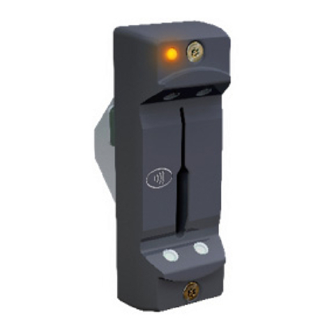
The MMR2 uses Near Field Communication (NFC) to read contactless EMV cards and mobile devices
as well as magnetic stripe cards.
1.1.2 MMR2 Install Diagrams
The drawings on the next 2 pages contain basic installation examples to assist with proper placement
of the MMR2 card reader.

MMR2 Card Reader Installation MMR2 Card Reader Installation
6MMR2 Installation and Service Manual Ver 1
Note: Although the diagrams reference SkimGard (IMSR) readers, these diagrams should be used for
MMR and MMR-BT installs, as well.

MMR2 Card Reader Installation MMR2 Card Reader Installation
MMR2 Installation and Service Manual Ver 1 7

MMR2 Card Reader Installation Electrical Installation
8MMR2 Installation and Service Manual Ver 1
card reader
1.2 Electrical Installation
1.2.1 MMR2 Wiring
The wiring for the MMR2, including all of the input and output termination points, is shown in the dia-
grams on the following pages.
Take care to wire all ends (card reader, circuit boards, door locks and additional power sources) cor-
rectly and to label the sheathed cables for input devices (card readers, exit switches, door-sense
switches, sensor devices) and output devices (electrical door locks, alarm controllers, etc.). Be sure to
make a list of the terminal functions the colored wires are assigned.
1.2.1.1 Wiring the Card Readers and Basic Input Devices
The basic input wiring for the MMR2 card reader is shown in the diagrams below.
Note: Although certain diagrams reference SkimGardTM/ IMSR readers, these diagrams should be
used for MMR and MMR-BT installs, as well.

Electrical Installation MMR2 Card Reader Installation
MMR2 Installation and Service Manual Ver 1 9
Note: The wiring diagram below applies to both the ACS-1E and ACS-1EUL.

MMR2 Card Reader Installation Electrical Installation
10 MMR2 Installation and Service Manual Ver 1
1.2.1.2 ACS-1EUL Card Reader and Input Device Wiring
The other ends of the sheathed cables and their connection to various ACS-1EUL input devices is
shown below.

Electrical Installation MMR2 Card Reader Installation
MMR2 Installation and Service Manual Ver 1 11
The wiring configuration for the Second card reader board is similar to that of the Controller.

MMR2 Card Reader Installation Electrical Installation
12 MMR2 Installation and Service Manual Ver 1
ACS-1EUL System with Input & Output Sockets and Terminations

MMR2 Installation and Service Manual Ver 1 13
Chapter 2
Post-Installation Checks and Testing
This chapter contains information about the Options Menu.
2.1 Post-Installation Checks ..........................................................................................................13
2.2 Post-Installation Testing............................................................................................................15
2.3 Troubleshooting ........................................................................................................................18
2.1 Post-Installation Checks
Once the MMR2 card reader has been installed, its functionality must be thoroughly tested.
2.1.1 Default Settings
Each MMR2 leaves the Parabit factory after passing a full set of operational tests. Any test configura-
tions are then removed and the MMR2 is returned to its default configuration.
During testing, the MMR2 card reader(s) are mated to the ACS-1E or ACS-1EUL Controller (and Second
Card Reader Board) and checked for operation before boards and readers are separated and
packed for shipping. In order to check the initial operation of the ACS-1E Controller, the installer should
know the default settings, which are listed in the table below.
TABLE 2–1. Controller Default Settings
Function Description Default Settings
BIN Files NYCE list of acceptable magnetic card
numbers.
Inserted in ACS-1E memory for both
card reader files with title: “Demo”
or “Reduced.”
Card Mode
One of five modes which determines how the
card reader filters magnetic cards
numbers.
Set to mode: “Any Card.”
Card Reader Relay
Activation Time
Delay time for an active door-control relay
after a valid card is read. 5 seconds
Controller Time Zone Selectable Time Zone Eastern Standard Time
Daily Schedule
24-hour per day, 7-day per week schedule
Map. Card readers can be set to CARD,
LOCK, OPEN, or [BLANK].
Card Readers are set to “Card”
24/7. Reader indicator glows amber.
Door Jam Detect Time
Time-value which determines when the
Controller will issue a “door open” alert. (Note:
available only if door contact is installed.)
60 seconds
Door Sense
Auto-Relock; cuts door-control activation
time down to one second when active.
(Note: available only if door contact is
installed.)
Normally-Closed (NC) with jumper
across the terminal block when door
sense switch is not required.

Post-Installation Checks and Testing Post-Installation Checks
14 MMR2 Installation and Service Manual Ver 1
2.1.1 Preliminary Tools and Materials
• 1x Small flat-blade screw driver (for wire terminal blocks)
• 1x Medium Phillips screw driver (for circuit board mounting screws)
• 1x Digital Multimeter {DMM} (with Low Resistance range or “Continuity” function)
2.1.2 Preliminary MMR2 Hardware Check
Make sure the white wires from the card readers are properly connected to the white wires of the
Tamper-Detect switch in the mounting collar or box. Make sure the card reader is properly seated in its
mounting collar or box and the Tamper-detect switch “finger” is depressed.
Door Sense Jumper (JP1)
Near coin-cell battery and Maintenance
Mode push-button. Sets the Door Sense
to normally-closed (NC) when in place.
Jumper in place on Door Sense terminal
block and on JP1.
Egress (Exit) Switch Input Input opens door (activate door relay) for
selected amount of time.
Normally-Closed (NC); with jumper
across the terminal block when Exit
switch is not required.
Egress Activation Time Delay time for an active door-control relay
after an Egress switch is activated. 5 seconds
Door Override Input Activates door-control relay(s).
Normally-Closed (NC); with jumper
across the terminal block when Door
Override output signal is absent.
Holiday Schedule Standard holiday schedule file for current
years (or next year). Standard Holiday Schedule in place
Port Number Value Internet port number value Port 2000
Sensor Configuration
Mapping
Allows configuration of Outputs 1 & 2 (and
I/O Relay Outputs), assignment of Card
Reader alerts, I/O Inputs, and Inhibit functions.
All assignments are blank
Suspect Card BIN File
System expects: 9999999999999999 string in
Stolen Card Binfile or Controller will lock up
after first card-read.
9999999999999999 in Stolen Card Binfile
Suspect Card Function
Controller scans up to 50 stolen or
“suspected” cards from a small Binfile, locks
down the Card Reader(s) and door control
relay(s) when a suspected value is detected.
Not selected/activated
TABLE 2–1. Controller Default Settings
Function Description Default Settings

Post-Installation Testing Post-Installation Checks and Testing
MMR2 Installation and Service Manual Ver 1 15
2.1.1 Visual Inspection of the MMR2 Card Reader
Conduct the following visual inspection of the card reader assembly by referring to the letters in the
diagram and corresponding checks below.
a. LED: Check the presence and color of the LED light indicator.
• Amber Light - Insert Card
• Green Light - Door Unlocked
• Red Light - Door Locked
b. Screws: Parabit-provided security torque screws must be used.
Note: NEVER use power tools to tighten Card Reader screws.
c. Sensors: All 4 sensors must be visible with no abnormalities.
d. Card Slot: Check the card slot for foreign objects.
e. NFC Logo: NFC Logo must be present and positioned along the LED side in the direction shown
in the picture.
2.2 Post-Installation Testing
Review the diagrams below and complete the tests for the MMR2 card reader.
c
c
b
b
d
e
a

Post-Installation Checks and Testing Post-Installation Testing
16 MMR2 Installation and Service Manual Ver 1
2.2.1 Main Card Reader Tests
Table of contents
Other Parabit Systems Card Reader manuals
Popular Card Reader manuals by other brands

Magtek
Magtek iDynamo 5 Quick installation guide

Microscan
Microscan MS-3 CCD quick start guide

Lexar
Lexar EXPRESSCARD COMPACT FLASH READER - DATASHEET REV... datasheet

Duali
Duali DE-600S user manual

Symmetry
Symmetry Javelin S884 Installation and user instructions

Linear
Linear AM-DPR Specification and installation instructions