Paradise Datacom P300 Series User manual

Docref: p:\p300\d-wp\p300h\p3x0h.wpd (&.pdf)
Handbook Issue 2.04,dated 5th May2005.
Covering softwarefeatures up toand including V4.54/58
2003
EN55022-ClassB
EN60950
Witham,Essex,CM83UJ,En eCollege,PA16803,USA.
Phone01376515636 (Int +441376...). Phone814-238-3450(Int +1814...)
PORTANTNOTE:THE
PARADISEDATACOMmaintains acontinuing programmeof product improvement
andthereforereservestheright tochangespecificationswithoutnotice
EN55024
Installation &OperatingHandbookfor
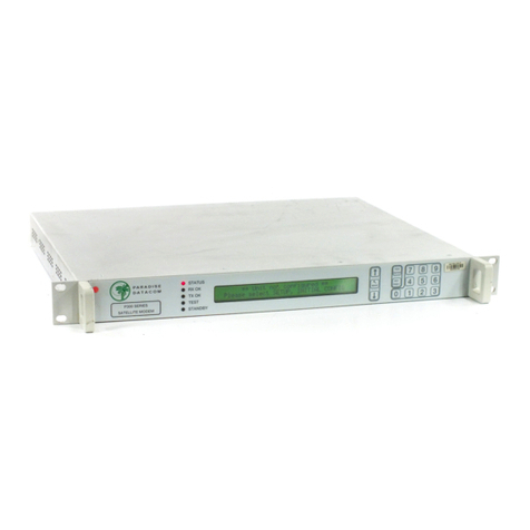
P300 SeriesSatelliteModems
(including P310 L-Bandand
TurboFECoptions)
Paradise DatacomLtd. Paradise DatacomLLC
1WheatonRoad 328InnovationBlvd
gland. Suite100,Stat
Fax01376533764 Fax814-238-3829
http://www.paradisedata.com
INFORMATIONANDSPECIFICATIONSCONTAINEDINIM
THISDOCUMENTSUPERSEDEALL PREVIOUSLYPUBLISHEDINFORMATION
CONCERNINGTHISPRODUCT

Tableof Contents
1EMC (ELECTROMAGNETIC COMPATIBILITY)ANDSAFETYNOTICES ...............7
1.1EMC......................................................................................................................................................7
1.2SAFETY................................................................................................................................................8
2INTRODUCTION ...............................................................................................................................9
2.1OVERVIEW..........................................................................................................................................9
2.2P300 SERIESFEATURES................................................................................................................10
2.3FEATURE SUMMARY.....................................................................................................................11
2.4FEATUREHIGHLIGHT.....................................................................................................................12
3DESCRIPTION .................................................................................................................................16
3.1OPERATION......................................................................................................................................16
3.2FAULT PHILOSOPHY.......................................................................................................................16
3.3ELECTRICALDESCRIPTION..........................................................................................................16
3.4FRONTPANELFEATURES.............................................................................................................17
3.5REARPANELDESCRIPTION..........................................................................................................18
3.6BLOCKDIAGRAM.............................................................................................................................21
4SUMMARYOF SPECIFICATIONS...........................................................................................23
5INSTALLATION AND CONFIGURATION .............................................................................42
5.1UNPACKING......................................................................................................................................42
5.2VISUALINSPECTION OFEQUIPMENT.........................................................................................42
5.3INTERFACE OPTIONS.....................................................................................................................42
5.4IFINTERFACE...................................................................................................................................42
5.5POWER UP........................................................................................................................................42
6MENUSYSTEM...............................................................................................................................43
6.1INTRODUCTION...............................................................................................................................43
THE1MINUTE GUIDETOFRONTPANELOPERATION ...................43
6.2MENUSTRUCTUREDIAGRAMS....................................................................................................44
6.2.1MenuStructureSheet1/ 7(Main: Status, Change).........................................................45
6.2.2Full Menu StructureSheet 2/ 7(Main:Monitor, Info).......................................................46
6.2.3Full Menu StructureSheet 3/ 7(Main: Log, Test, Setup, Action, Help)..........................47
6.2.4Full Menu StructureSheet 4/ 7(Main, Change, User-Opt, Operation)...........................48
6.2.5Full Menu StructureSheet 5/ 7(Change,Tx)..................................................................49
6.2.6Full Menu StructureSheet 6/ 6(Change,Rx)..................................................................50
6.2.7Full Menu StructureSheet 7/ 7(Change, BUC/LNB)......................................................51
6.3Status SCREENDISPLAY................................................................................................................52
6.4SETUP-INITIALCONFIGURATION MENU...................................................................................56
6.5CHANGEMENU................................................................................................................................56
6.6CHANGE, TX MENU.........................................................................................................................57
6.6.1Change, Tx/Rx,SERVICEMenu.......................................................................................57
6.6.2Change, Tx/Rx, Service, CLOSEDNETWORK................................................................58
6.6.3Change, Tx/Rx, BASEBANDMenu...................................................................................60
6.6.4Change, Tx/Rx, Baseband, CONTINUOUSMenu...........................................................60
6.6.5Change, Tx/Rx, Baseband, DROP/INSERTMenu...........................................................61

6.6.6Change, Tx/Rx,Baseband, OTHERMenu......................................................................65
6.6.7Change, Tx, CLOCKINGMenu.........................................................................................66
6.6.8Change, Tx, MODULATORMenu.....................................................................................68
6.6.9Change, Tx/Rx, Modulator, IFFREQUENCYMenu.........................................................68
6.6.10 Change, Tx/Rx, Modulator, MODULATIONMenu..........................................................68
OFFSETQPSK(OQPSK) PRIMER...........................................................................................69
6.6.11 Change, Tx/Rx, Modulator, FECMenu...........................................................................69
6.6.12 Change, Tx/Rx, Mod/Demod, REED-SOLOMONMenu................................................71
INTRODUCTIONTOREED-SOLOMON...................................................................................71
6.6.13 Change, Tx/Rx, Mod/Demod,SCRAMBLER Menu.......................................................72
6.6.14 Change, Tx, Modulator, CARRIERMenu.......................................................................74
6.6.15 Change, Tx, Modulator, POWERLEVELMenu.............................................................74
6.6.16 Change, Tx/Rx, Modulator, SPECTRUMINVERTMenu...............................................75
NOTEONBPSKSPECTRUMINVERSION..............................................................................75
6.6.17 Change, Tx, Modulator, AUPC(Software>=V2.12).......................................................75
6.6.18 Change, Tx, Modulator, AUPC, MODEMenu................................................................76
6.6.19 Change, Tx, Modulator, AUPC, MAXMenu....................................................................76
6.6.20 Change, Tx, Modulator, AUPC, MINMenu.....................................................................77
6.6.21 Change, Tx, Modulator, AUPC, SLEWRATEMenu......................................................77
6.6.22 Change, Tx, Modulator, AUPC, TARGETEB/NOMenu................................................77
6.6.23 Change, Tx, Modulator, AUPC, TOLERANCEMenu.....................................................78
6.6.24 Change, Tx, Modulator, AUPC, CARRIERLOSTACTIONMenu.................................78
6.6.25 Change, Tx/Rx, ESC/AUX/BAMenu...............................................................................79
6.6.26 Change,Tx/Rx, ESC/Aux/BA,DEFINE(IDR) Menu......................................................79
6.6.27 Change,Tx/Rx, ESC/Aux/BA,DEFINE(IBS) Menu.......................................................81
6.6.28 CustomIBS OverheadAllocation....................................................................................83
6.6.29 Change, Tx/Rx, ESC/Aux/BA,ASYNCESCMenu........................................................84
6.6.30 Change,Tx/Rx, ESC/Aux/BA, ConfigAsync, BAUDRATEMenu.................................85
6.6.31 Change,Tx/Rx, ESC/Aux/BA, ConfigAsync, FORMATMenu......................................85
6.6.32 Change,Tx/Rx, ESC/Aux/BA, ConfigAsync, SETASREMM&C.................................85
6.6.33 Change, Tx/Rx, ESC/Aux/BA, INTERFACESMenu......................................................86
6.6.34 Change, Tx/Rx, ESC/Aux/BA, AUDIOLEVELSMenu...................................................87
6.6.35 Change,Tx/Rx, ESC/Aux/BA, BACKWARD ALARMSMenu........................................88
6.7CHANGE, RX MENU.........................................................................................................................89
NOTEON RX=TXFUNCTION...................................................................................................89
6.7.1Change, Rx, SERVICEMenu............................................................................................90
6.7.2Change, Rx, BASEBANDMenu........................................................................................90
6.7.3Change,Rx, BUFFER/ CLOCKINGMenu.......................................................................92
6.7.4Change, Rx, Buffer / Clocking, STATIONCLOCKMenu.................................................92
6.7.5Change, Rx, Buffer / Clocking, RXCLOCKMenu............................................................93
6.7.6Change, Rx, Buffer / Clocking, BUFFERSIZEMenu.......................................................94
6.7.7Change, Rx, Demod,Menu...............................................................................................96
6.7.8Change, Rx, Demod,IFFREQUENCYMenu..................................................................96
6.7.9Change,Rx, Demod,MODULATION Menu.....................................................................96
6.7.10Change, Rx, Demod,FECMenu.....................................................................................96
6.7.11 Change, Rx,Demod, REED-SOLOMONMenu.............................................................96
6.7.12Change, Rx, Demod, SCRAMBLERMenu.....................................................................96
6.7.13 Change, Rx,Demod, SPECTRUMINVERTMenu........................................................96
6.7.14Change, Rx, Demod, SWEEPMenu...............................................................................97
6.7.15 Change, Rx, Demod, AUPCMenu..................................................................................98
6.7.16 Change, Rx, ESC/AUX/BAMenu....................................................................................98
6.7.17 Change, Rx,RX=TXMenu..............................................................................................98
6.8CHANGE, TERR-INTFCMENU.......................................................................................................99
6.8.1Change, Terr-intfc, ELECTRICAL.....................................................................................99
6.8.2Change,Terr-intfc, CONTROLLINES............................................................................100
6.8.3Change, Terr-intfc, CARDSPECIFIC.............................................................................101

6.9CHANGE, REM-M&CMENU..........................................................................................................102
6.9.1Local Control TAKEAWAY/ GIVEAWAYSelection.....................................................102
6.9.2Change, Rem-M&C, CONFIGUREMenu.......................................................................103
6.10 CHANGE,USER-OPTMENU......................................................................................................104
6.10.1Change, User-Opt, THRESHOLDSMenu....................................................................104
6.10.2Change, User-Opt, OPERATIONMenu........................................................................104
6.10.3Change, User-Opt,Operation, ACTIONSMenu...........................................................105
6.10.4Change, User-Opt, Operation,TERRESTRIALMenu..................................................105
6.10.5Change, User-Opt, Operation, Terrestrial, PCMBEARER CRCMenu.......................106
6.10.6Change, User-Opt,Operation, SATELLITEMenu........................................................106
6.10.7Change, User-Opt,Operation, TERR/SATMenu.........................................................108
6.10.8Change, User-Opt,Operation, ALARMSMenu............................................................109
6.10.9Change, User-Opt, DISPLAYMenu..............................................................................109
6.10.10Change,User-Opt, AGC OutputMenu.......................................................................109
6.11 CHANGETIME/DATE MENU.......................................................................................................110
6.12 CHANGE,BUC/LNB MENU..........................................................................................................110
6.12.1Change, BUC/LNB,TX/BUCMenu...............................................................................110
6.12.2Change, BUC/LNB, Tx/BUC, BUCTYPEMenu...........................................................110
6.12.3Change, BUC/LNB, Tx/BUC, DC&REFERENCESMenu..........................................113
6.12.4Change, BUC/LNB, Tx/BUC, SHFFREQUENCYMenu..............................................113
6.12.5Change, BUC/LNB, Tx/BUC, SHFPOWER/UNITSMenu...........................................114
6.12.6Change, BUC/LNB, Tx/BUC, BUCCONTROLMenu..................................................114
6.12.7Change,BUC/LNB, Rx/LNBMenu................................................................................115
6.12.8Change,BUC/LNB, Rx/LNB,LNBTypeMenu..............................................................115
6.12.9Change, BUC/LNB, Rx/LNB, DC&REFERENCESMenu..........................................116
6.12.10Change, BUC/LNB, Rx/LNB, SHFFREQUENCIESMenu........................................116
6.12.11Change,BUC/LNB, TUNE REFMenu........................................................................117
6.13 MONITORMENU..........................................................................................................................117
6.13.1Monitor, DEMODPERFORMANCEMenu...................................................................117
6.13.2Monitor, TERRESTRIALBERMenu.............................................................................118
6.13.3Monitor, CARRIERID'sMenu.......................................................................................118
6.13.4Monitor, DISTANTEb/No&BERMenu........................................................................118
6.13.5Monitor, AUPCMenu.....................................................................................................119
6.13.6Monitor,BUCMenu........................................................................................................119
6.14 INFOMENU...................................................................................................................................120
6.15 LOGMENU....................................................................................................................................121
6.15.1LOG,AUTOLOG Menu..................................................................................................121
6.16 TEST MENU...................................................................................................................................124
6.16.1Test, LOOPBACKSMenu.............................................................................................124
6.16.2Test, RF&FECMenu...................................................................................................126
6.16.3Test, PSU S +TEMPMenu...........................................................................................126
6.16.4Test, Int'BERTMenu.....................................................................................................127
6.16.5Test, Int'BERT, OFF/CHANNELMenu........................................................................128
6.16.6Test, Int'BERT, PATTERNMenu.................................................................................130
6.16.7Test, Int'BERT, MODEMenu........................................................................................130
6.16.8Test, Int'BERT, RESULTSMenu..................................................................................131
16.17 SETUPMENU..............................................................................................................................132
16.18 ACTIONMENU............................................................................................................................132
16.19 HELPMENU................................................................................................................................133
16.20 SERVICEMENU..........................................................................................................................133
16.20.1Service, USERPARAMETERS Menu........................................................................134
16.20.2Service,FACTORYPARAMETERS Menu.................................................................134
7.MENUSCREENSFOR SPECIALIST OPTIONS...............................................................135
7.1CUSTOMFRAMINGMENUS.........................................................................................................135

7.1.1Change, Tx/Rx,Service, CUSTOM Menu......................................................................135
7.1.2Change, Tx/Rx, Service, CUSTOM, IBSMenu..............................................................135
7.1.3Change, Tx/Rx, Service, CUSTOM, IDRMenu..............................................................137
7.2IBS/SMSOPERATIONWITH2048KBPSCONTINUOUSDATA................................................139
7.2.1Change, Tx/Rx, Baseband, Continuous,2048k G.732Menu(IBS)...............................139
7.3CUSTOMIDR OPERATIONWITH2048KBPSCONTINUOUSDATA........................................141
7.3.1Change, Tx/Rx, Baseband, Continuous, 2048kMenu(IDR).........................................141
8.APPLICATION NOTES...............................................................................................................142
8.1DOPPLER&PLESIOCHRONOUS BUFFERING.........................................................................142
8.2DETERMININGCLOCKINGSCHEMESANDBUFFERSIZE.....................................................143
8.2.1ClockLoopAtOne End:..................................................................................................143
8.2.2NoClockLoop..................................................................................................................143
8.2.3DeterminingBuffer Size...................................................................................................144
8.3PARTIALINSERTANDMULTIDESTINATIONALWORKING.....................................................145
8.4CHOOSING OPTIMUM CUSTOMVALUESOFRS N&K............................................................146
8.5NOTESON DATA RATES &SYMBOLRATES............................................................................147
8.6DETERMINING EXACTMAXIMUMESCBAUDRATES.............................................................148
8.7CLOSEDNETWORK PLUS ESC...................................................................................................149
8.7.1OverheadRates...............................................................................................................149
8.7.2ClosedNetworkPlus ESCviatheCustomServicemenu..............................................150
8.7.3ESCchannel withmis-match configurations...................................................................150
8.8CROSSREFERENCE TOSDM300 D/I &FRAMINGMODES....................................................152
8.9V.35SCRAMBLERS........................................................................................................................154
8.10 INTERWORKINGDIFFERENTMANUFACTURERS EQUIPMENT..........................................155
8.11 INTRODUCTIONTOAUPC(AUTOMATICUPLINKPOWER CONTROL)..............................156
8.11.1Introduction.....................................................................................................................156
8.11.2ConfiguringAUPCforoperation....................................................................................159
8.12 TUTORIALONCARRIER/NOISE&Eb/NoMEASUREMENTS................................................161
8.12.1Introduction.....................................................................................................................161
8.12.2Derivation of Eb/Nofrom(C+N)/N.................................................................................161
8.12.3Practical Implications of DisplayedEb/No.....................................................................162
8.12.4Eb/NoExplanatoryDiagram..........................................................................................163
8.12.5TablestoConvert (C+N)/NtoEb/No.............................................................................164
91FOR 1OPERATION................................................................................................................166
9.1THEORY...........................................................................................................................................166
9.2SWITCHING PHILOSOPHY...........................................................................................................166
9.3PRACTICAL1FOR1IMPLEMENTATION....................................................................................167
10BOOT CODEOPERATION.......................................................................................................168
10.1FLASHSOFTWAREUPDATE.....................................................................................................168
10.2OTHERBOOTCODE OPTIONS.................................................................................................169
APPENDIXA:DATAINTERFACEINFORMATION ...............................................................170
GENERAL...............................................................................................................................................170
P1440 INRS422MODE........................................................................................................................171
P1440INV.35 MODE............................................................................................................................172
P1440 INRS232MODE........................................................................................................................173
P1440 ING.703 MODE.........................................................................................................................174
P1440INX.21 MODE............................................................................................................................176
MIL-STD-188-114AINTERFACE..........................................................................................................178

P1451 EUROCOMD/1`D`&`G`PLUS MULTI-STANDARDINTERFACE......................................179
APPENDIXB:MODEMCONNECTORPINOUTS...................................................................182
REMOTE M&C(RS485/RS232)CONNECTOR..................................................................................182
InterconnectingDevices UsingRS485.....................................................................................183
1FOR1INTERFACE............................................................................................................................185
ALARMS&AGC CONNECTOR...........................................................................................................186
ASYNC ESCCONNECTOR.................................................................................................................187
ESC/AUX&BACKWARD ALARMSCONNECTOR............................................................................189
APPENDIXC:UPGRADEINFORMATION................................................................................193
APPENDIXC1:MODEMCAPABILITIES&UPGRADES...................................................................194
APPENDIXC2:FEATURESCREENS.................................................................................................194
APPENDIXC3:FEATURESONDEMOEXPIRESOON....................................................................199
APPENDIXC4:ASYMMETRICLOOPTIMING...................................................................................199
APPENDIXC5:UPGRADEAVAILABLE..............................................................................................199
APPENDIXC6:FEATURESNOTAVAILABLE...................................................................................199
APPENDIXD:REMOTEM&C ........................................................................................................200
REMOTEM&CPROTOCOL.................................................................................................................200
Summary...................................................................................................................................200
Character Format / BaudRate..................................................................................................200
ElectricalInterface.....................................................................................................................200
MessageStructure....................................................................................................................201
MessageCategories.................................................................................................................202
Listof All RemoteM&CMessages...........................................................................................203
APPENDIXE: CUSTOMER SPECIFICFEATURES...............................................................207
RELAY MODE SETTING.......................................................................................................................207
FAULT MODE SETTING.......................................................................................................................208
UNCOMMITTEDDACOUTPUTCONTROL.......................................................................................211
APPENDIXF:FRAMINGAND DROP/INSERT OVERVIEW...............................................212
IBS/SMSFRAMING...............................................................................................................................212
IBS/SMSService Features.......................................................................................................212
IBS/SMSDefinition....................................................................................................................212
Implementationof Timeslot IDMaintenance............................................................................214
SignallingSystemsIntroduction: CCS, CAS&RBS................................................................215
SignallingOver Satellite............................................................................................................215
CASMultiframe.........................................................................................................................216
IDR FRAMING........................................................................................................................................219
IDRServiceFeatures................................................................................................................219
APPENDIXG: FAULT MESSAGES AND ACTION TABLE ................................................220

1.EMC(ELECTROMAGNETICCOMPATIBILITY)AND SAFETY NOTICES
IMPORTANT- PLEASEREADTHISINFORMATIONBEFOREINSTALLATIONANDUSE
1.1.EMC
(ELECTROMAGNETICCOMPATIBILITY)
TheP300ModemSatelliteModemshave beenshowntocomplywiththefollowing standards:
Emissions:EN55022Class B;Limitsandmethodsofmeasurementofradiointerference
characteristicsof InformationTechnologyEquipment.
Immunity:EN50024Information technologyequipment immunitycharacteristics
Extensivetesting hasbeen performedtoensurethattheunitmeetsthesespecificationswhen
configuredwithanyorall ofitsavailableoptions,suchas IFband,impedance,IFsynthesiserstepsize,
datarates, etc.
Toensurethatthe P300Modemswill maintaincompliance withthese standardsplease ensurethatthe
followingpointsareobserved:
1)Theequipment MUSTBEOPERATEDWITHITS COVERON ATALLTIMES. If it isnecessary
toremovethecoverforanyreason,thenyoumustensurethatthecoveriscorrectlyrefitted
beforenormaloperation.
2)Damagetothefrontpanelkeyboardmembraneormechanicaldamagetothechassiscould
invalidatecompliancy.Pleasecontactthe factoryifdamageoccursforadvice oncontinued
operation.
3)Forthebasebanddatainterfacesall 'D'typeconnectorsmusthavegroundingfingersonthe
plugshelltoguarantee continuousshielding.Theback-shellsmustcomplytotherequirements
ofVDE0871and FCC20708,providingatleast40dBofattenuationfrom30MHzto1GHz.A
goodqualitycablewithacontinuousouter shield, correctlygrounded, must be used.
4)Connectionstothetransmit andreceiveIFinterfaces mustbemadewithdoublescreened
coaxial cable- for exampleRG223/U.
Installationswhichignoretheserequirementswill invalidatethe compliancytoEMC
specifications.
P300H P300 SeriesModemInstallation and Operating Handbook Page 7

P300H P300 SeriesModemInstallation and Operating HandbookPage 8
1.2SAFETY
ToensureoperatorsafetytheP300Modemshavebeendesignedtocomplywiththefollowing safety
standard:
EN60950 Safetyof InformationTechnology Equipment, includingelectrical businessmachines.
Prior toinstallationandoperation, pleaseensurethatthefollowingpointsareobserved:
Environmental
Theequipmentisdesignedtooperateinastatic19-inchracksystemconforming toIEC297-2.
Operationoftheequipmentintransportableinstallationsand vehiclesequipped withthe means of
providingastableenvironmentispermissible.Operationofthe equipmenton vehicles,shipsoraircraft
withoutmeansofenvironmentalconditioningmay invalidatethesafetycompliancy.Pleasecontactthe
factoryforfurtheradvice.Operation oftheequipmentinanenvironmentotherthanthatstatedinthe
specificationswill alsoinvalidatethesafetycompliancy.
Theequipment must not beoperatedinanenvironment inwhichtheunit isexposedto:
*Un-pressurisedaltitudesgreater than2000 metres
*Extremesof temperatureoutsidethestatedoperating range
*Excessivedust
*Moistureor humidatmospheres above95%RH
*Excessivevibration
*Flammablegases
*Corrosiveor explosiveatmospheres
Installation
TheequipmentisclassifiedinEN 60950asapluggableequipmentclassAforconnectiontothemains
supply.Assuch it isprovidedwithamains inletcordsuitableforuseinthecountryofoperation.In
normalcircumstances thiswill beofanadequatelengthforinstallationintherack.If themainscable
provestobetooshort thenanyreplacementmusthaveasimilartypefuse(iffitted)andbe
manufacturedtoasimilarspecification.Forexample,lookforHAR,BASEC or HOXXX-Xratings onthe
cableand theconnectorendsmarkedwithBS1636A(UKfreeplug 13amp); BSI, VDE,NF-USE,UL,
CSA,OVE,CEBEC,NEMKO,DEMKO,SETI, IMQ,SEVandKEMA-KEUR fortheIEC6ampfree
socket. SchukoandNorthAmerican freeplugsmusthavesimilar markings.
Theinstallationof theequipment andtheconnectiontothemainssupplymust bemade incomplianceto
localornationalwiringregulationsforacategoryII impulseover-voltageinstallation.Thepositioningof
theequipmentmustbesuch thatthemainssupplysocketoutletforthe equipmentshouldbenearthe
equipmentandeasilyaccessibleorthatthereshouldbeanothersuitablemeans ofdisconnectionfrom
themains supply.
TheequipmentisdesignedtooperatefromaTNtypepowersupplysystemasspecified inEN60950.
Thismeans asystemthathas separateearth,lineand neutralconductors.Theequipmentis not
designedtooperatewithanITpower systemwhichhasnodirect connection toearth.
CAUTION: Thisunit has DOUBLEPOLE/ NEUTRALFUSING.

P300H P300 SeriesModemInstallation and Operating HandbookPage 9
2.INTRODUCTION
2.1OVERVIEW
Thishandbookdescribeshowtoinstall andconfiguretheP300Series SatelliteModems.Thisincludes
theoriginalP300,theP300Turbo,P310L-BandandP311mixed L-Band/IFModems. Whereever
referenceismadetotheP300orP300Seriesmodemit appliestoall productsunlessspecifically
noted.
TheP300 Seriesmay besuppliedequipped withdifferentfeaturesetstosuit differentapplications.This
means thatthemixoffeaturesavailableinany modem(suchasDrop/Insert, IDRframingetc)maybe
tailored tosuit anyuserrequirement, however typically theyaregroupedintooneoffourstandard
configurationsasfollows:
P300 / P310-VSATFeaturesfor useinVSATapplications.
P300 / P310-IBSFeaturesfor IBS/SMSuse(orthinrouteIDRbelowT1) services.
P300 / P310-IDRFeaturesfor IBS/SMSAND IDRservices(IDRatT1or greater).
P300 / P310-TCMFeatures foruseinTCM,TCM/IDR,IBS/SMSandstandardIDR
services.
Thetableonpage 11summarises thedifferentfeatures,andwhichfeaturesareavailableinthefour
standardconfigurations.
TheP300SeriesModemsaredesignedfor operationinatypicalgroundstationenvironment, providing
adatalinkbetweengeographicallydistantsitesviasatellite.Likeitspredecessors,it isphysicallysmall,
light,andof ruggedconstruction, allowingit alsotobeused inmobileandflyawayterminals.
TheP300Seriesprovides adataport ontheterrestrialside whichprovidesRS422,V.35,andRS232
softwareselectableinterfacesonboth25pinEIA530and37pinRS449connectors.OptionalG.703
interfacesprovideeitheraT1orE1(1544kbpsor2048kbps)G.703interface inaddition tothestandard
threeinterfaces.Themodemcouplesintothe groundstation up/downconverterchains ontheRFside
ateither70MHzor, if theWidebandIFfeatureisavailable(standardonP300-IBS andabove), 140MHz.
Thestatusofaunit isavailableexternallyon`formc`relayoutputsdesignedtoconnecttostation
monitoringsystem. Themodemalsoprovides acompleteremoteMonitor &Control(M&C) port, allowing
thestatustoberemotelymonitored and theunit controlledor theconfiguration changed.
If Async ESC featureisavailable(standardonP300-IBSandabove)themodemcan providean
asynchronous EngineeringService Channelcarriedacrossthesatellitelinkasanoverheadaddedtothe
maindatachannel. The ESCchannelcanbeinternallylinkedtotheremoteM&Cport, allowing any
modemtobemonitoredorcontrolledfromthedistantendofthesatellitelink.Inaddition,external
equipment(suchasradiotransceivers)if coupledintothe remoteM&Cportmayalso beaccessed
remotelyover thesatellitelink.
HigherspecifiedP300modemsadditionallyfeaturemanyadvanced functionsincludingvariablecode
rateReed-Solomon,theultimateinT1/E1Drop/Insert functionality,separateESC&Aux channelswith
independentelectricalinterfaceselection,abuiltinBit ErrorRateTester(BERT)whichcanrun
continuouslythroughtheESC orAuxchannelsloggingresultsinthetrafficlog,plus aClosed NetPlus
ESC(`minimumoverhead`) modeinwhichtheoverheadvariesfrom<0.5%towhateverisrequiredto
support virtuallyanyasync ESCchannel requirements.
Toprovideas simpleas possiblesoftwareupgradefacility,theembedded monitor&controlsoftware
canbechangedwithoutopeningtheproduct. Unlike otherequipmentwhichholdstheembeddedM&C
softwareinEPROMs(requiringreplacementEPROMstobeshipped,changed&returned), theP300
ModemM&Csoftwareisdownloaded intoFLASHmemoryviaarearpanelserialport fromaPC.A
process whichrequiresnotoolsand iscompletedin30minutes.Foroperatorsrequiringthelatest
featuresorupgrades,the mostrecent releaseoftheinternalM&CsoftwareisavailableonourWebsite
(http://www.paradisedata.com) for freedownload.

P300H P300 SeriesModemInstallation and Operating HandbookPage 10
2.2P300 SERIESFEATURES
Asthishandbook coversthefull featuresetoftheP300Modem,someofthetextwill notbeapplicable
tomodemsequipped withonlyasubsetofthepossiblyfunctionality.Inthetextwhereit describes
featureswhichareoptional it usesphraseslike:
RequiresDrop/Insert feature(standardonP300IBSandabove)
Throughoutthetextthe descriptionofthefeature(Drop/Insert ) isconsistent, andwhereverit is
referencedit alsostates whichofthefourstandardconfigurations thisfeaturebecomes availableas
standard.Intheaboveexamplethe Drop/Insert featureisstandardontheP300-IBSconfiguration,and
all modelsabove, i.e. theP300-IBS, P300-IDRandtheP300-TCM.
TheP300Serieshas beendesignedtomakefieldupgradesaseasyas possible,and many features
may beaddedbyfrontpanelentryofa FeatureCode whichcan beissuedby ParadiseDatacom.
SomeOptionshowevermayrequireextrahardwaretobeadded(egextraboardsorjust IC s)but thisis
easilyperformedbyacompetenttechnician.Thetableonthefollowingpageindicateswhichfeatures
may beaddedfromthefront panel, andwhich requiretheadditionof extrahardware.
It mightappearthatthewords`Feature` and`Option` areusedinterchangeably.Inpractice howeverwe
haveattemptedtouse `Options`torefertofunctionswhichalwaysrequirehardwaretobe fitted,
whereasweuse`Features`torefertofunctionswhichmay be softwareenabled without extrahardware
being fitted.Forexamplewerefer tobothIDRandG.703 Options (astheseeach requireanextraboard
tobefitted), whereaswerefertoDrop/Insert and Reed-Solomon Features (as thesearesoftware
enabledfeatureswithinthebasicmodemhardware).
If youarenewtotheequipmentit isworthconfirmingwhatfeatures andoptionsareavailableinthe
equipment youhave. If it isoneof thefourstandardconfigurationsthenacopyof thenext pagemight be
usefulasyouworkthroughthemanualtopreventyou havingtoreferbacktoit. Ifit isauserdefined
featureset, then refertoAppendixC2,whichexplainshowtodeterminethefeatures availableonany
P300Seriesmodem.
Whenspecifyingthe featuresetofamodem,anExcelspreadsheet, whichmimicsthefollowing tableis
availableonrequest. Thespreadsheetdirectlycalculatesthe costofthe varyingfeaturesyoumay
specify,andwhenprintedmay beused toordermodems.It alsodirectlygeneratesanordercodefor
anyuser featureset youmay specifyandlistsany warnings withthefeatureset youhave specified.

P300H P300 SeriesModemInstallation and Operating HandbookPage 11
2.3FEATURE SUMMARY
Feature
*meansh/w option
P300 SeriesConfigurationDescription
VSATIBSIDRTCMUSER
BaseModem BPSK/QPSK/OQPSK, 4.8kbpsto512kbpsmodem
RS422 / V.35 / RS232 interfacewith25&37 pinconnectors
50MHz-90MHzIF interfacewith100Hzresolution
ViterbiFEC* ViterbiFEC, rate1/2,3/4,7/8inBPSK,QPSKand OQPSK
SequentialFEC* SequentialFEC, rate1/2,3/4,7/8in BPSK, QPSK, OQPSK
TurboFEC(TPC)* TurboFEC, variouspreset code rates(inc1/2,3/4,7/8&0.789)
INTELSAT
Reed-Solomon
Reed-Solomon outerFEC, withn, k, t =126, 112, 7
(switching to225, 205,10or219,201, 9with4/8deep interleaving
asrequired forIDR&TCM/IDR)
Wideband IF Wideband 50MHz-180 MHzIF (instead of 50MHz-90MHz)
HighDataRates Datarates512kbps-5Mbpsin addition toBaseModemrates
A
syncESC Variable rateESCchannel forClosed NetplusESCoperation
HighrateIBS/SMSESC(withIBS/SMSfeature)
A
syncaccesstoIDR8ksyncESCchannel(withIDR option)
IBS/SMS IBS/SMSframing(toIESS309)
Drop/Insert NormalT1/E1linearorderDrop/Insert
IDR * IDR operation(toIESS308), P1348 Emulation&
32/64kbpsAuxdatain placeof one/bothIDR audioESC
PRBSTester Internal BitErrorRateTester(BERT, overhead modesonly)
8PSK/TCM 8PSKwith rateTrellisCodeModulation (toIESS310)
ExtendedD/I Independent timeslot re-ordering on Tx&Rx
Signalling (CASforE1&RBSforT1)
RxPartial Insert formulti-destinationalworking
Timeslot IDmaintenanceforN=1to31 withIBS/SMSorClosed
Net plusESCoperation
CustomFeatures
A
rbitrary`n`&`k`forReed-Solomon (withRSfeature)
Custom&Min O/Hmodes(withIBS/SMSorIDR options)
Customallocation of IBSo/hbetween ESC/ Auxchannels
Monitor/AGC* Demod Rxcarriersignal level monitor
0-10VAnalogoutput of carriersignallevel,Eb/No, orRxoffset
frequency(inaddition tonormalAGCoutput)
Constellation monitorport
A
UPC
A
utomaticUplinkPowerControl
(requiresAsyncESCfeaturetooperate)
1544kbpsG.703 * 1544kbpsG.703 interface in addition toRS422 / V.35 / RS232
interface(softwareselectable)
2048kbpsG.703 * 2048kbpsG.703 interface in addition toRS422 / V.35 / RS232
interface(softwareselectable)
Optionsmarked withan asteriskwill requireboardsorsingle IC stobe addedtothe unitin ordertoadd the option atalaterdate.
featureswithout an asteriskcanbe addedbyentering a FeatureCode intothe front panel of the equipment.

P300H P300 SeriesModemInstallation and Operating HandbookPage 12
2.4FEATURE HIGHLIGHT
Thislist highlightssomeof the notablefeaturesabout theP300SeriesModems:
All P300SeriesModems (iebasemodemfeatures)
Variabledataratein1bps stepswithfastacquisitionevenat lowdatarates
BPSK, QPSK, and Offset QPSK(OQPSK)
Viterbi FEC(toIESS308/309), rate1/2, 3/4&7/8inBPSK, QPSKandOQPSK.
100HzIFresolution
RS422,V.35,andRS232DCEinterfaceonbothEIA53025pinand RS44937pin
connectors.
CanaccommodateViterbi &Sequential FECsimultaneously
Built in1-FOR-1RedundancyController(requires onlycables,passiveIF
splitter/combiner &secondmodemfor complete1:1injust2U)
0-99msDoppler/plesiochronousbuffer
Full remoteM&C
1000eventtrafficlog,withfacilitytocontinuouslylogcircuit performanceatregular
intervals(logsaverage&worst caseEb/Noand/or userBER)
`InTheRack`upload of revised internal software
25dBTxIFlevelcontrol in0.1dBsteps
BandlimitedIFinputcapableofoperatingwithhigh compositepower(ieIFinputnot
`wide open` andaffectedby out of bandsignals)
1PPMinternalfrequency&clock reference,withexternalstationclock input&options
for higher stabilityinternal references
CCITT&INTELSATV.35scramblersforclosednetworkoperation,withadditionaltwo
modes forcompatibilitywithFDCandLinkabit proprietarypatterns.
Deferredalarmatusersetservice limits(individualEb/No,BER&Bufferslip
thresholds)
Frequency lockedclock loops(ienotphaselocked)immunetoclock hitscausedby
equipment suchasrouters
Comprehensivemonitoringand statusdisplay,withexplicit faultdescriptionsofmost
significantfault for Tx&Rxpaths
P5001-FOR-NSwitchavailable allowingmixed interfaceswithin1:Nsystem
Supportedby Alphawave CAMmulti-productremoteM&C systemwhichcanprovide
centralisedloggatheringon aPC (includingloggedcircuit performancefigures,eg
Eb/Noevery10mins)
Softwareincludes two`UserVariables`toaccommodatecustomuserrequirements
(suchasspecialalarmhandling), allowingspecialuserrequestedfeaturestobeadded
whilst still keepingcommonsoftware
Cleardisplay,intuitivemenus with`Normal`selections &efficientuserinterfacewithfull
keyboard
TxorRxpaths maybeselectedas`Off`, mutingappropriatealarmsinTxorRxonly
applications
Threeform`C`relays providingpromptTx/RxTrafficfaults,as wellasapromptunit
(equipment) fault andadeferredalarm.

P300H P300 SeriesModemInstallation and Operating HandbookPage 13
P300/ P310-IBSAdditional Features
INTELSATReed-SolomonFeature
AfullyINTELSATcompliantReed-SolomonCodecproviding
*Automaticselection ofappropriateINTELSAT valuesof`n,k&t` and
interleaving depthfordatarate&serviceselected(n,k,t=126,112,7by
default, switchingto225,205,10or219,201,9with4/8deepinterleaving as
requiredfor IDR &TCM/IDR)
*Provides improvedlowEb/Noperformanceinframedmodeduetouseof
extendedthresholdframesyncalgorithms
*Enhanced capabilitieswiththe`CustomFeatures` feature(seelater)
WidebandIFFeature
Theextensionof the50MHz- 90MHzIFrangeup to50MHz- 180MHz
HighDateRateFeature
Theextension ofthedataraterangetoinclude ratesabove512kbpsup to5.0Mbps
(dependingonmodulationandFEC modes)
AsyncESC Feature
Theadditionofahighrateasync ESCchannel, whichmaybeinternallylinkedtothe
M&Cport toprovidecontrolofdistantendequipment(inall overheadmodes)without
additional cabling. TheAsync ESCfeatureprovides asfollows:
*Support for any async ESC rateinClosedNetPlus ESCmode,providinga
scalableoverhead whichaddstheminimumpossibleoverheadtothesatellite
datatoprovidethe baudrateselected(addingfrom<1%to100%overhead).
ClosedNetPlusESC modealsoprovidesan optionalbackwardalarmfacility
andabove32kbpsasynchronous scramblertoreplacethenormalerror
multiplyingV.35 self synchronisingscrambler.
*AhighrateasyncESCchannelinIBS/SMSoverhead,achieving 2400Baud
witha64kbpscarrier(requiresIBS/SMSfeature,standardonP300-IBSand
above)
*Asyncaccess totheIDR8kbpssynchronousESCchannel. (requiresIDR
option,standardon P300-IDRandabove)
*SoftwareselectableRS232, RS485orRS422interface.
IBS/SMSFeature
SatelliteFraminginaccordance withIBS(toIESS309)andSMS(EESS501),
including:
*Userassigned Tx,andcorrespondingRxdisplay of, StationID,ChannelID&
SpareIDwithinSMSoverheadtoaidcarrier identification.
*AhighrateasyncESCchannel inIBS/SMSoverhead (see AsyncESCabove)
Drop/Insert Feature
ThemostsophisticatedDrop/Insert functionsofanysatellitemodemwhilststill
maintainingsimplicityof configurationandoperation.TheDrop/Insert featureprovides:
*1544kbpsT1-D4&T1-ESFand2048 kbpsG.732operation
*Arbitrary&independent timeslot selectionfor Drop&Insert
*Full support for CRC-4inG.732modeandCRC-6inT1-ESFmode
*Terrestrial error monitoringbased onFrameAlignment Words(FAW) or CRC
*G.732`Ebit`processing,allowing thedisplayofthe outbound terrestrialerror
rate
*Loopthroughorgenerationof localbearerontowhich toinsert theRxdatafrom
anynormal clock source(egstation clock, clockfromsatellite, internalclock)
*AutomaticgenerationofbackupbearersoRxtrafficisnotlostif Dropbearer
intoTxfailsandbearer isloopedthroughtotheInsert mux topick upRxdata
*Timeslot IDmaintenance evenwithClosed Net Plus ESCcarriers
*Enhancedfeatureswiththe ExtendedD/I Feature(seelater)

P300H P300 SeriesModemInstallation and Operating HandbookPage 14
P300/ P310-IDRAdditional Features
IDR Option
SatelliteFraminginaccordance withtheIDRspecification (toIESS308), including:
*StandardIDRframingwith2x32kbpsADPCMaudioESC,asynchronous
8kbpsESC datachannel, andfourbackwardalarms
*Enhancedfeatureswiththe CustomFeatures feature(seelater)
*IndependentESC &Aux Portstoreplacethe sharedESC/Auxport ofthe base
modem.TheESCandAux portsareactiveinall framedmodes.Theyprovide
thefollowing features:
ESCPort providesafrontpanelselectableRS232,RS422,or
RS485interface.In IDRMode it provideseitherasynchronous
interfacetothe8kbpsIDR ESCchannel, or (if theAsyncESCfeature
isavailable,standardonP300-IBSandabove)an async interface
supportingupto4800or9600Baudeg fordistantendM&Cviathe
IDRoverhead.ThissameESCport, althoughpart oftheIDR option,in
ClosednetPlusESCorIBS/SMSmodes provides ahigh rate
asynchronousESCinterface(eg2400Baud at64kbpsinstandard
IBS/SMSmode,any Baud rateforClosedNetPlus ESC). Again
typicallyusedfor distant endM&Cviatheoverhead.
AuxPort provides afrontpanelselectableRS232andRS422
interface.In IDRMode it providessynchronous32or64kbpschannel
inplace ofoneorboththe 32kbpsADPCMESCaudiochannels.In
IBS/SMS&MinimumOverheadmodes itprovidea synchronous port
whichcanbeconfigured tousefrom1/32to21/32oftheIBS/SMS
overhead(egforinternalorexternalBER testing). Whensetto1/32
andused asynchronouslyit providestheINTELSATcompliantLow
RateESCchannel.
PRBStesterfeature
TheinternalPseudoRandomBinarySequence (PRBS)Bit ErrorRateTester(BERT)
offersthefollowing features:
*PRBScan passthroughthemaindatachannel, ortheESC orAuxchannelsof
theoverhead inparallelwiththemaindatachannelinanymodewhere
overheadisadded.
*BERTresultscanbeloggedinthetrafficlogatusersetintervals,providing
continuoustrafficqualitymonitoringandrecordingwhenoperatingthroughthe
overheadinparallel withthe maindata.
*Compatiblewithpatternsusedby test equipment such astheFirebirdetc.
P300/ P310-TCMAdditionalFeatures
8PSKwith2/3rateTCM (50%bandwidthof QPSK1/2rateViterbi)
ExtendedD/I Feature
TheextendedDrop/Insert providessignificant extrafeaturescomparedtothebasic
Drop/Insert featureset:
*Arbitrary&independent timeslot re-ordering for Drop&Insert
*Full support forG.732ChannelAssociatedSignalling(CAS)overIBS/SMS
links*T1-D4&T1-ESFRobbedBit Signalling(RBS) maintenanceover IBS/SMSlinks
*Maintenanceof timeslot IDfor N=1to31 inclusivewhenusing any framing
(normallyonlyN=1, 2, 3, 4, 5,6,8, 10, 12,15, 16, 20, 24aremaintained for
IBS/SMSandthereisnoIDmaintenancefor IDR)
*Insertionof onlypartial receiveddata(formulti-destinational working)

P300H P300 SeriesModemInstallation and Operating HandbookPage 15
`CustomFeatures` Feature
Withrespect tothe Reed-Solomon, theCustomFeaturesprovides:
*Codewordlength(`n`) variablefrom60to255
*Error correct bytes(`t`) variablefrom2to20instepsof two
*Selectable4and8depthinterleaving
Withrespect tothe Framing, theCustomFeaturesprovides:
*CustomIDR Modesincluding 16kbps ADPCMmodeprovidingall normalIDR
facilitiesina64kbps overhead,orallnormalIDRfacilities plus a32kbpsAux
channelinthenormal96kbpsoverhead(whichallowsaninternalorexternal
PRBStesttoruninparallelwiththe traffictomonitortheservice quality). The
overheadcanalsobereducedtoprovide reducedIDR facilities with64kbpsor
32kbps overheads.
*CustomIBS/SMSmodes including facilities formultidestinationalIBScarriers
with4backwardalarms,andMinimumOverheadmodes(amoreconfigurable
versionofClosedNetPlus ESC)wheretheoverheadvariesfromthestandard
16/15(6.7%). Inminimumoverheadmodetheusersetsthe requiredESC
Baudrateandtheoverheadis scaledtotheminimumvaluetoprovidethe
servicerequired.Forexample2048kbps with9600BaudESC inoverheadof
<1%, or 64kbpsdatawithESCrates upto38.4kBaud
Withrespect tothe ESC Channels
*Full userallocationoftheoverheadbetweenESCandAuxchannelsin
IBS/SMSmodes,providingusercontrolovertherelativeratesoftheasync
ESCchannel andthe syncAuxchannel.
1st GenerationTurboProductCodeForwardErrorCorrection(TPCFEC)
Turbocodecfor bandwidth and power efficiency
Softwarecansupport upto31preset coderates (initial rates includesrate1/2, 3/4, 7/8&
0.789)
3/4Ratefor compatibilitywithindustryDe-FactoTurbo.
1/2,3/4,7/8Rateallowswitch toTurbo&bettermargin/qualityofservicethan Viterbi
insamespacesegment (egfixedcapacityonlonglease)
0.789rateprovidesoptimisedperformancenear 3/4ratefor newer circuits.
2nd GenerationTurboProductCodeForwardErrorCorrection(TPCFEC)
Y8PSKwithrates of 3/4and7/8
Y7/8Ratefor compatibilitywithindustryDe-FactoTurbo.
Monitor/ AGCOption
Monitor anddisplayof Rxcarrier level
Rear panel PSKconstellationmonitor point
Anuncommitted0-10VDCanalogueoutput, setfromthefrontpaneltooutput
AGC/Signallevel(forantennapointing/tracking), Eb/No,userBERoranyother
parameter availableinternally.
AutoUplink PowerControl (AUPC) Feature
AUPC viaasyncESCchannelonIBS/SMS,IDRand ClosedNetPlusESCcarriers(ie
overheadsdownto<1%).
AutomaticallyInterleaves AUPCwithdistantend remoteM&C (if active)onESC
channel.
Monitor onlyoption for distant endEb/No&BERmonitoring without powercontrol.
Addsoptionalautomaticregular loggingofAUPCdeltapower anddistant endEb/No.
Uni-directional, bi-directionalandbroadcast (Txonly/ self monitor)modes.

P300H P300 SeriesModemInstallation and Operating HandbookPage 16
3DESCRIPTION
3.1OPERATION
TheP300SeriesmodemsarefullysoftwarecontrolledandwiththeexceptionoftheoptionalG.703
interfaceoptiontherearenolinks orswitchesusedtoconfiguretheunit. Thisenablesallcontroland
configurationtobeperformedeitherlocallyfromthefrontpanel, orbyremoteM&C.Localcontrolisby
frontpanelkeyboard, andalarge, easytoread,80characterLCDdisplay, withclear, intuitive menus for
configurationand control. All theset-upparametersarestoredinnon-volatilememorywhichwillretain
dataforaminimumof3years,withnopowerapplied.Thetransmit and receivefunctions ofthe Modem
areindependent,sothattheymaybeoperatedatadifferentdatarates,IFfrequencies,ordifferent
servicesif required.
Likeall ParadiseDatacomproducts,theP300Series includesatrafficlog,which storesthelast500
events,suitablytime-stamped.It can automaticallyadd severalmeasuredparameterstothelogat
operatorsetintervals,includingaverage &worstcaseEb/No,average&worstcaseestimateduser
BER,average&worstcase estimated uncorrectedBER,andthebufferfill state.Thelogged
performancemonitoringallowsinvestigationintocustomerreportsofpoorlinkperformance,andcan
provideausefulcorrelation against weather conditions,etc.
3.2FAULTPHILOSOPHY
Faultsaresplit intotwocategories:
a) UNITFAULTS:Equipment failures(suchasasynthesiser lockfailure).
b) TRAFFICFAULTS:Datapathfailures, (suchasalackof input clock).
Afull descriptionofeverydetectedfault, itscategory(unitortraffic), and the corresponding actiontaken
isprovidedinAppendixG-Fault MessagesandActionTable.TheresponseofthefrontpanelLED
indicatorsandexternal fault relays respondisdescribedinthefollowingsections.
3.3ELECTRICALDESCRIPTION
TheP300 modemcomprisesofasinglemainmodemPrintedCircuit Board(PCB)withfouroptional
additional boards:
Optional G.703interface(twodifferent boardsfor T1or E1operation).
Optional IDRESCboard,whichprovidesfor all theIDRESCrequirements
OptionalMonitor/AGC boardwhichprovidesauserscalableAGCoutputandaconstellation
monitor point.
OptionalTurboFEC daughtercard
FortheP310,anL-Banddaughterboardisalso fittedinternallyabovethemainmodemboard,and
further three internal options arepossible:
Reference oscillator options(several ofvaryingstabilities)
Aninternal100WPSUtoprovideaDCfeed toanexternal BUC
AnoptionalFSKcommunications board,toenableamodemandBUCtobooperatedfromthe
modemfront panel (andtoprovideclosed looppower control totheBUCflange).

P300H P300 SeriesModemInstallation and Operating Handbook Page 17
3.4FRONTPANELFEATURES
P300 Modemfrontpanelview
Keyboard
Thekeyboardisofthemembrane type(anintegralpartofthe frontpanel), whichprovideadirecttactile
feel. Thereare15keysintotal-numberkeys intherange0to9,an uparrowkey( ), downarrowkey
(), Óß×Ò key, ÇÛÍñÛÒÌÛÎ key, and ÒÑñÐÎÛÊ key.
LCD display
Thisbacklit displayprovides2lines of40characterseach andishighlylegibleeveninconditionsof high
ambientlight. TheLCDprovides detailedinformationaboutthestatus andconfigurationoftheunit,and
whenappropriate, promptstheuser toenter dataviathe keypad.
onitorportM
Thecircularmonitorportavailableonthefrontpanel
nnector(a`D`typeconnectorinsteadofthedifficult
criptionofthe "AsyncESCconnector"underthe
peratoris
urr
ff,thenthe TxorRxtraffichasfailed duetoan external
tsettings.
If the STANDBYLED isAmber,theTxcarrierisoff.It maybeintentionallyswitched off, orit
may bemutedduetoeitherafault, anexternalmutesignal, orifina1-FOR-1redundantpairit
may bethestandbyunit.
ofprevious productshas beenmovedtotherear
panelandisnowcombinedontotheAsyncESCco
toobtain8pin`din`audiotypeconnector).Seethedes
age.rearpaneldescription,whichstartsonthenextp
LED Indicators
FiveLEDson thefront panel providesummaryfault
information, sothat evenwhentheLCDisunavailable
orstatusdisplay(suchaswhentheof
reconfiguringtheunit, andamenu isdisplayed), the
entstatuscanalwaysbeassessed.If anyofthec
LED'sindicateafault, press Óß×Ò,thenselect ͬ¿¬«-
todisplaythe current fault condition.
In normal operation thereshouldbe three GREENLED's showing.
Ifthe StatusisRED, theunithasfailed due tointernal orpossiblyexternal conditions. Refer to
thetext ontheLCDStatus screenandrectifyifpossible.
Ifthe TXOKorRXOKLED'sareo
fault, againrefer tothetext ontheLCDStatusscreenand rectifyif possible.
Ifthe TESTLEDisAMBER,atestmodeorloopbackisactive,press Óß×Ò,andselect Ì»-¬
toqueryorchangethetes

P300H P300 SeriesModemInstallation and Operating Handbook Page 18
3.5REARPANELDESCRIPTION
Attherearofunit arealloftheconnectorsnecessaryfortheusertointerfacetheModemtothe outside
world;IFinputand outputtofrequency conversion equipment, terrestrialdataconnection,stationclock,
alarms&AGCoutput, remoteM&C, ACpowerandso on.
Fromleft toright, therear panel connectorsare:
IECmainspowerconnector/voltageselector/fuse
TheModemisdesignedtooperatefromamainsACsupplyof100-240V(-15%+10%,ie85Vto264V
attheconnector). TheIECconnectorincorporatestwofuses,independentlyfusingbothliveand neutral
lines.Accesstothefuses isprovidedbyaslideouttray.Bothfuses arestandard20mmtype,rated
3.15A,oftheslow-blow(timedelay)type. ALWAYSREPLACETHEFUSEWITHONEOFTHESAME
TYPEANDRATING.
P300 Modemrear
p
anelview
(
IDR &G.703o
p
tionsfitted
)
Chassisgroundstud
ThisisanM4studfor connectingasafetyearthconductor directlytothechassisof the unit.
Fan
Thefanmaybeselectedtobetemperaturecontrolledorpermanentlyactive(iethefactthatitisnot
runningdoesnotindicateit has failed). Usethetestmenutodisplaytheinternalunit temperatureif in
doubt, thefancomesonat 26°Candoff at 24°C.
StationClock
Thisconnectorisa75 BNC femalewhich acceptsa1-10MHzsignal, eitherasquarewaveof>1Vp/p
(egaG.703 para10`synchronisingclock`) orasinusoidatapowerlevelof0dBmorgreater. An
alternativeStationClock signalatRS422interfacelevelscanbeappliedtotheAsync ESCconnector.
Eithersignalcan beused bythemodemasareferenceforthereceive outputclock (theStationClock
doesnot havetobethesamerateasthedataasaninternal PLLconvertsbetween rates). Inadditionif
theRxClockingissettousethe StationClock andtheTxClockingisset to Rx , then theStation Clock
alsosourcestheinternallygeneratedTxClock (Tx&Rxdataratesareindependent). Finally, if a10MHz
signalisapplied,thissignalmayalsobeusedinplaceofthe internalreferencefortheTxandRxIF
synthesisers.
1:1Redundancy connector
TheModemhasabuilt-in1for1redundancycontrollerwhich connectstothecorrespondingportof
anotherModemviathis9pinmale'D'typeconnector. Acomplete1:1redundancy systemrequiresonly
twomodems,a1:1controlcable(onthisport), adatasplit (`Y`) cable,andpassive splitters/combiners
fortheIFports(orsplitters/combinersalreadypresentinthesystem). Connectiondetailsaregivenin
AppendixB, andanoverviewof 1for 1operationisprovided insection9startingon page177.
RemoteM&Cconnector
Thisisa9pinfemale'D'typeconnectorwhosepinoutandinterfacelevelsare`SA-bus`compliant. The
Modemcanbeset tooperatewitheitherParadise/FDCorSA-bus protocols.Theelectrical interfacecan
beselectedbetweenRS232(fordirecttoPCapplications)&RS485(formultidropapplications). The
RemoteM&Cport maybe internally linked(ienocables)totheAsyncESCport foroverthesatellite
distant end RemoteM&C control. PinoutdetailsareinAppendixB.

P300H P300 SeriesModemInstallation and Operating HandbookPage 19
RxIFinput
Thisconnector isaBNCfemaleand canbeused aseither a50 or 75 input. Theallowablesignal level
ofthe desiredcarrier atthe input of the modemisfrom-60dBmto-30dBm(P310:-70dBmto-20dBm). A
levelof-45dBmisrecommended.The maximumcompositepowerlevelthatshouldbeapplied tothis
port is30dBabovethedesiredcarrier, uptoamaximumof 0dBm(P310: Composite+35dBctomax of-
10dBm).
AlarmsandAGC connector
Thisisa15pinmale'D'typeconnectorthatprovidesaccesstothe three form`C'relaycontactsthat
indicatealarmconditions.Alsoprovidedon thisport if theMonitor/AGCoptionisfittedisanuncommitted
analogoutput, which bydefault providesanAGCoutput, butwhichmaybeselectedviathefrontpanel
toprovideotheruser requestedsignals(eg Eb/No, RxIFoffset frequency, or other uses implemented as
required). Thealarmrelayshavethefollowing definitions:
Unit Fault:A unit fault exists, i.e. anequipment failure.
TrafficPrompt: ATxor Rx trafficfault exists.
Deferredalarm: Oneof thefollowing conditionsexists:
Thereceive BERisgreaterthantheuser definedthreshold.
Thereceive Eb/Noislower than theuser definedthreshold.
Buffer slips aremorefrequentthantheuser set threshold.
ABackwardalarmisbeingreceivedfromeither the satelliteor terrestrial
ports.
Full pinoutdetailsareprovided inAppendixB.Thealarmrelay functions can bechanged,See
`RelayMode` inappendixE.
AsyncESCconnector
This15pin`D` femaleconnectorprovidesasupersetofthefeaturesfoundpreviouslyonthefrontpanel
circular8pin`din`connector. It includesanRS232serialport for theloadingor revisedinternalsoftware
fromaPCortheprintingoftheunitstrafficlogtoaserialprinter/PC terminalemulator.If the
Monitor/AGC option isfittedit provides I,Q,andsymbol clock outputstomonitor thereceiveconstellation
(inordertoviewreceivedsignalqualityon an oscilloscope).WhentheIDRoption ISNOT fitted,it
providesanRS232/RS422/RS485asynchronous port foreitherthehigh rateAsyncESCfacility(for
IBS/SMSorClosedNetPlusESCservices)ortheIBS/SMS`lowrateINTELSAToversampledESC
facility`(which isconfiguredas theAuxdatachannelonthemodem). WhentheIDRoption IS fitted,
separateportsfortheESCand Auxchannelsonthe IDRcardareactivated,and ESC/Auxaccesson
thisasyncport isdisabled.Finally,thisconnectoralso providestheport foranRS422compatible
StationClock(seetheStation Clockparagraphonthe previouspage).
TxIFoutput
ThisconnectorisaBNCfemaleandcanbeusedaseithera50 or75 output.Theoutputpowerlevel
canbevariedfrom0dBmto-25dBmon 0.1dBsteps fromthefront panel(P310: -5dBmto-30dBm).
ESC&Auxconnector
Thisconnectorisfitted aspart oftheIDR option(StandardonP300-IDR&P300-TCM), itprovides
access to:
Fourbackwardalarmform`c`outputs,andthe4backwardalarminputs,togetherwithaRx
summaryalarmsignalfordirectconnectiontothebackwardalarminputs.Notethatthesecan
beusedbothinIDRmodes,and(if theIBSand`CustomFeatures`features areavailable)a
customIBSmode,whichallowsfourbackwardalarmsforlowrateIBS multidestinational
carriers.

P300H P300 SeriesModemInstallation and Operating HandbookPage 20
TwoAudioESC ports(4wire600 ,+7to-16dBm). InadditiontonormalIDRESCoperation
these portsmayalsobeusedinIBS modestogeneratea64kbpsIBScarrier comprisingjust the
two32kbpsADPCMaudiochannels, ora128kbpsIBScarriercomprising64kbpsdata(fromthe
maindatainterface ofthe modem)plusthetwo32kbpsADPCMaudiochannels.Thisisan
emulationofthemostpopularmodes oftheP1348/P1448voice/datamuxcardused oftenin
SNGapplications.
AnRS232/RS422/RS485Port forsync/asyncESC traffic,thisport replaces theshared
ESC/AuxaccessviatheAsyncESC connectoron themainunit. Usedtoprovideaccesstothe
8kbpssynchronousIDRESCchannel. If theAsync ESCfeatureisavailable(standardonP300-
IBSandabove)thenAsyncaccesstothe 8kbpschannelisalsoavailable.Againif the Async
ESCfeatureisavailablethisport alsoprovidesthehighrateAsyncESConIBS/SMSorClosed
Net PlusESCservices
AnRS232/RS422 port forsync/asyncAuxtraffic, thisport replaces thesharedESC/Aux access
viatheAsyncESCconnectoron themainunit. TheAuxport provides32or64kbpsaccessto
theIDRoverheadinplaceof one or bothof theIDR32kbpsADPCMAudioESC channels. If the
IBS/SMSfeatureisavailablethenthisport may beconfiguredtoprovideeither theIBS `lowrate
INTELSAT oversampled ESCfacility`, or ahigherrate synchronous channelwithintheIBS/SMS
overhead.
PinoutdetailsareprovidedinAppendixB.
TerrestrialInterfaceConnectors
TheP300 providesasstandardboth25 pinEIA530and37pinRS449femaleDCE connectors.NOTE
thatthese aresimplywiredinparallelandyoushouldnotconnectbothsimultaneously.The electrical
interfaceisfrontpanelselectabletobeRS422,V.35,andRS232.NormallyforRS232 operationthe
EIA530 connector wouldbeused(which isstandard25pinRS232compatible) andfor RS422the37pin
RS449 connector. Theoldstyle34pin`Winchester` connectorfavouredforV.35interfaceshaspoor
EMCperformanceandso couldnotbeincorporated whilstmaintainingCEcompliance.If thisstyleof
connector isrequiredthenanexternal adaptorcablemust beused.
If the G.703option isfitted,then inaddition toRS422/V.35/RS232,G.703isalsoavailableasa
softwareselectableinterface standard.T1(1544kbps)G.703isabalanced100 signal, andisprovided
onboth`D`typeconnectorswhenG.703isselectedfromthefrontpanel. WhentheE1(2048kbps)
G.703optionisfitted theninadditiontoprovidingsupport forthebalanced120 signalonboth`D`type
connectorsanadditionalpairofBNCconnectorsareprovidedtoaccepttheunbalanced75 interface
standard.THESELECTIONBETWEEN75 and120 ISMADEBYASWITCHON THEE1G.703
OPTIONnotbysoftware.Aswiththe25/37pinconnectors,donotconnectsignalstoboththe BNCand
`D` typeconnectorssimultaneously.
InadditionaswitchonboththeT1and E1G.703optionscontrols whathappens totheG.703port
whenpowerisremoved.EithertheG.703portscanbesettogohighimpedance (usedin1:1
redundancyoperation)orit canbeconfiguredtolooptheG.703inputbacktotheoutput(typicallyused
whenDrop/Insert isinoperationandthesamePCMbeareriscascadedthroughseveralmodems).
Again(asit affectswhathappenswhenpowerisremoved)thisisSETBYASWITCHONTHECARD
not by software.
Finally,forspecialcustomerrequirementsit ispossibletofitdifferentinterfacestothisport. Notethat
UNLIKEPREVIOUSPRODUCTStheinterfacedoesNOTsimplyunplug.Insteadit isconstructedas
part ofthemainmodem,andrequires`snappingoff` and aconnectortobesolderedinplacebeforea
replacement cardcan befitted.
Standby LED
ThisLEDmirrorsthefrontpanelstandbyLED,so thatfromtherearoftheequipmenttheoperatorcan
tell if the carrier isoff, or moreimportantlywhichunit of a1:1pairisthe offlineunit.
Other manuals for P300 Series
1
This manual suits for next models
11
Table of contents
Other Paradise Datacom Modem manuals

Paradise Datacom
Paradise Datacom Quantum User manual

Paradise Datacom
Paradise Datacom Vision Series User manual

Paradise Datacom
Paradise Datacom PD60S User manual

Paradise Datacom
Paradise Datacom P300 Series User manual

Paradise Datacom
Paradise Datacom P300-VSAT User manual

Paradise Datacom
Paradise Datacom Evolution Series User manual